

SBIG STX Series Operating Manual
Operating Manual
STX Advanced Series
CCD Cameras
SBIG Imaging Systems A Division of Diffraction Limited.
59 Grenfell Crescent, Unit B, Ottawa, ON Canada, k2G 0G3
Tel: 613.225.2732 | Fax: 225.225.9688| E-mail: tpuckett@sbig.com | www.sbig.com
© 2016 Diffraction Limited. All rights reserved. The SBIG logo are trademarks of Diffraction Limited,
All other trademarks, service marks and tradenames appearing in this brochure are the property of
their respective owners.

Note: This equipment has been tested and found to comply with the limits for a Class B digital device
pursuant to Part 15 of the FCC Rules. These limits are designed to provide reasonable protection against
harmful interference in a residential installation. This equipment generates, uses, and can radiate radio
frequency energy and if not installed and used in accordance with the instructions, may cause harmful
interference to radio communications. However, there is no guarantee that interference will not occur in a
particular installation. If this equipment does cause harmful interference to radio or television reception,
which can be determined by turning the equipment off and on, the user is encouraged to try to correct the
interference by one or more of the following measures:
• Reorient or relocate the receiving antenna.
• Increase the separation between the receiver and the equipment.
• Connect the equipment into an outlet on a circuit different from that to which the receiver is
connected.
• Consult the dealer or an experienced radio/TV technician for help.
Shielded I/O cables must be used when operating this equipment.
You are also warned, that any changes to this certified device will void your legal right to operate it.
OPERATION Manual for STX Series
Cameras Revision 1.
3
Dec 2016
2

TABLE OF CONTENTS
1.0. CAMERA HARDWARE ...................................................................................................................................... 4
1.1. Introduction and Overview .......................................................................................................... 4
1.2. Unpacking the Camera.................................................................................................................. 4
Standard Items:....................................................................................................................... 6
Optional Items: ....................................................................................................................... 7
1.3. Parts and Assembly ....................................................................................................................... 8
1.4. Connectors....................................................................................................................................... 9
[A] Tracking CCD Focus Adjustment................................................................................. 9
[B] Remote Guide Head Port ............................................................................................... 9
[C] USB Port ........................................................................................................................... 9
[D] SCOPE Port.....................................................................................................................10
[E] I2C-AUX Port..................................................................................................................10
[F] Ethernet............................................................................................................................10
[G] Power...............................................................................................................................10
[H] Water In / Out ...............................................................................................................10
1.5. Attaching the camera to a telescope. ..........................................................................................11
1.6. Connecting the Relay Cable.........................................................................................................11
1.7. Attaching the Remote Head.........................................................................................................11
1.8. Connecting water hoses................................................................................................................12
1.9. Extending the USB cable ..............................................................................................................12
1.10. Opening the Front Cover - Regenerating the Desiccant Plug................................................13
1.11. Gas Purging..................................................................................................................................14
1.12. Indicator Lights ...........................................................................................................................14
1.13. Opening the Back Cover - Changing the Fuse.........................................................................15
1.14. Using a Relay Adapter Box with the STX ................................................................................15
1.15. Camera Resolution......................................................................................................................17
1.16. Camera Field of View .................................................................................................................18
1.17. Focal Length, Resolution and Field of View............................................................................19
2.0. CAMERA SOFTWARE .......................................................................................................................................20
2.1 Installing Software .........................................................................................................................20
Installing CCDOps ................................................................................................................20
Installing the SBIG Drivers...................................................................................................20
Linking the Drivers ...............................................................................................................21
2.2. Using the Camera..........................................................................................................................22
Establishing a Link with CCDOps ......................................................................................22
Camera Setup.........................................................................................................................22
Taking Sample Dark Frames................................................................................................22
Further Investigations...........................................................................................................23
2.3. Specific Activities ..........................................................................................................................23
Ethernet Configuration.........................................................................................................23
Web Browser..........................................................................................................................23
Making the Autoguiding Connection.................................................................................23
2.4. Third Party Software.....................................................................................................................24
CCDSoft ..................................................................................................................................24
MaximDl .................................................................................................................................24
Support and Developer Resources......................................................................................................24
Appendix A – Adjustments and Maintenance .......................................................................................................25
Firmware Updates.................................................................................................................................25
Internal Tracker Focus ..........................................................................................................................25
Desiccant Regeneration ........................................................................................................................25
Cleaning the CCD and the Window ...................................................................................................26
3

Appendix B - Capturing a Good Flat Field .............................................................................................................27
B-1. Technique ......................................................................................................................................27
Appendix C – Camera Specifications.......................................................................................................................28
Appendix D – Connector and Cables.......................................................................................................................29
Power Jack .....................................................................................................................................................................29
Scope Port ......................................................................................................................................................................29
I2C/AUX Port ...............................................................................................................................................................29
Product Description
The SBIG STX Series represents the ultimate in astronomical imaging systems. The
integrated design allows the user to select either Ethernet or high speed USB 2.0 connection
to the control computer. The Model STX-16803 uses Kodak’s KAF-16803 CCD with 16
million pixels at 9 microns. The sensor measures almost 37mm square. The built-in tracking
CCD is a Kodak KAI-340S with 640 x 480 pixels at 7.4 microns. The STX series has
superior cooling to -50 degrees C below ambient with air only. Water-cooling is also
ossible.
p
Built-in Guiding CCD with Adjustable Focus: The guiding CCD in the STX cameras is a
KAI-340 CCD with 640 x 480 pixels at 7.4u. As the imaging CCDs get larger, the guiding
CCD gets pushed farther away from the center of the optical axis. Depending on the nature
of the optical system, this can cause the image on the guiding CCD to be slightly out of
focus when the image on the main CCD is in focus. To address this, STX cameras have a
user accessible adjustment for changing the focal point of the on-board guiding CCD.
For external guiding, the same same KAI-340 CCD is also used the optional Remote Guide
Head, and in the new STX Guider accessory for the FW7-STX filter wheel. The STX
Guider allows you to use the smaller, less expensive 50 mm square filters, and increases the
guider FOV with focal reduction optics. The smaller filters also mean that the FW7-STX
wheel can hold 7 filters instead of 5.
4

.0. CAMERA HARDWARE
1
Congratulations and thank you for buying one of Santa Barbara Instrument Group's STX
Series CCD cameras. These large format cameras are SBIG's seventh generation CCD cameras
and represent the state of the art in CCD camera systems with their low noise and advanced
capabilities. The STX Series cameras include several exciting new features: internal and
optional external self-guiding (US Patent 5,525,793), enhanced cooling capabilities, both high
speed USB 2.0 interface and Ethernet interface, plus other innovative features found nowhere
else.
1.1. Introduction and Overview
These cameras have two CCDs inside a sealed chamber, one CCD is used for guiding and
the large one for imaging. An optional remote guiding head may be added for guiding through
an external optical system or through an off-axis guider placed before the camera. The low noise
of the read out electronics virtually guarantees that a usable guide star will be within the field of
the guiding CCD for telescopes with F/numbers F/6.3 or faster. The new cooling design is
capable of exceptional performance even in warm climates. The relay output plugs directly into
most recent commercial telescope drives and is easily adaptable to virtually any drive system.
As a result, you can take hour long guided exposures with ease, using either the built-in guiding
CCD or the remote guiding head. The internal guiding CCD eliminates differential deflection of
guide scope relative to the main telescope and requires no radial guider setup hassles. The
remote guiding head allows for a convenient alternative when imaging through narrow band
filters where suitable guide stars may be difficult to find. This dual tracking mode capability,
coupled with the phenomenal sensitivity of the CCD, will allow the user to acquire observatory
class images of deep sky images with modest apertures! The technology also makes image
stabilization possible through our Adaptive Optics accessory.
1.2. Unpacking the Camera
It is always a good idea to check over your new camera to make sure that you have
received all necessary parts and standard accessories. Each STX Series camera is packed in a
deluxe custom carrying case. This case contains all the items necessary to operate your camera.
5
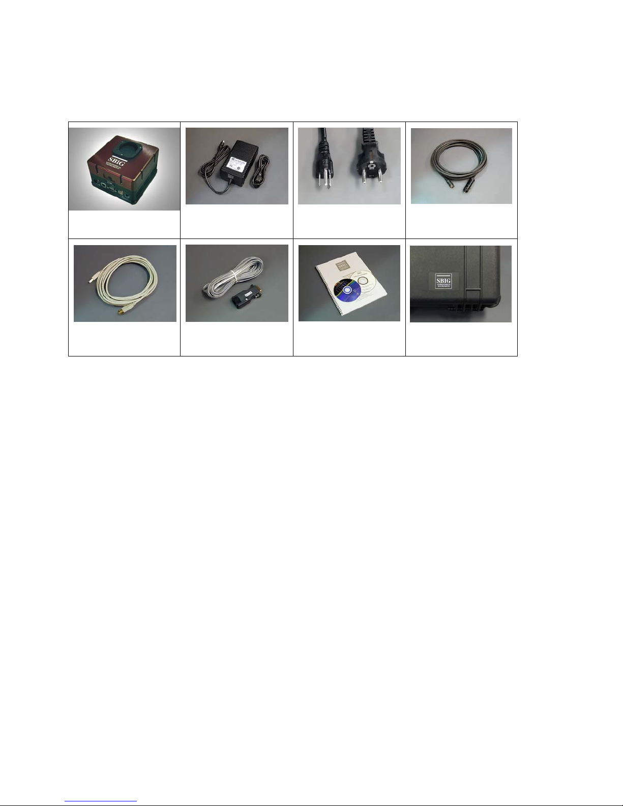
Standard Equipment for STX Series Cameras:
Power Cable
Extension
Custom Case
STX Camera
USB Cable
Universal Power
Supply
Tracking Cable /
Adapter
AC Cord
Software and
Manuals
Standard Items:
Camera Body
The STX Series Camera Body incorporates an imaging CCD, built-in and guiding CCD,
two-stage cooling, high-speed USB interface, Ethernet interface and opto-isolated relays
for telescope control. An accessory plate with 3” threaded aperture is fixed to the front
of the camera body for attaching to your telescope adapter. Due to the large size of some
CCDs used in the STX series cameras, a 2” nosepiece is too small to use without
vignetting the image. Rack handles are also attached to the camera body at the factory.
In addition to making the camera easier to handle in the dark, these handles also protect
the fan housing when the camera is placed on a flat surface or when it is packed in its
carrying case.
Universal Power Supply
The STX's universal power supply enables operation of the camera from 100 to
240VAC, 50-60 Hz. Note that the power supply has a different pin configuration than
the camera power port. The supplied 9 foot extension power cable must be used between
the power supply and the camera. This extension cable provides the correct pinout for
the camera. Use only the power supply provided with the STX camera. The earlier
model STL cameras also have a 6 pin power port, however the power supplies provided
with STL cameras do not provide sufficient current to operate the STX series cameras.
6

Power Supply Extension Cable
7
This 9 foot cable extends the distance the power supply may be placed away from the camera. It
is also much more flexible than the short lead provided with the power supply. Finally, the
extension cable adapts the four-pin output of the power supply to the six-pin DIN plug at the
camera.
Regional AC Cord and Plug
AC cords with either European or North American style plugs are provided. Must specify at time
of order.
14’ USB Cable
A standard 14’ USB cable is supplied
Relay Cable
The tracking cable is a 6 conductor flat cable with 6 pin modular telephone style plugs at both
ends
Software and Manuals
A complete package of camera control software, drivers for both 32 bit and 64 bit Windows O/S
and manuals are included.
Custom Case
Carrying cases provided for the STX Series cameras are high quality, waterproof, dustproof,
crushproof .
Optional Items:
Remote Guide Head
The optional STX Remote Guide Head contains a KAI-340S CCD identical to the guiding CCD
that is built into the camera. This remote head allows you to use a separate guide scope or offaxis guider to place the guiding CCD outside the filter wheel for convenience when imaging
through narrow band filters or anytime you wish to use an external guider.
FW5-STX, FW7-STX Filter Wheel
50mm and 65 mm filter wheels are available for the STX camera. Filter sets are offered by
Baader Planetarium, Custom Scientific and Astrodon.
STX Guider
This product attaches to the front of a FW7-STX filter wheel, turning it into a self-guiding filter
wheel. The STX Guider is directly compatible with the AO-X adaptive optics unit.
AO-X
The SBIG AO-X is a lar
cameras, including th
minimal backfocus while offering a large 3″ aperture optical
KAF-16803 CCD senso
ge aperture AO designed to be compatible with all STX and STXL series
e STX-16803, STXL-16200, STXL-11000 and STXL-6303. The AO-X requies
r.
element, which is large enough to cover the

Nikon and Canon Lens Adapters
Adapter allows the use of Canon or Nikon 35mm camera lenses on Research Series
cameras for wide field imaging.
1.3. Parts and Assembly
The black anodized portion of the camera body contains the CCD chamber, electronics,
desiccant plug, gas purge valve, heat exchanger, fan and a power supply for 12VDC operation in
the field. The red front cover contains the shutter mechanism and mounting plate with 3 inch
threads. The front cover may be removed from the camera body without exposing the CCD
chamber to the air. The accessory plate is shimmed at the factory to provide a flat mounting
surface that is parallel to the CCD. Under normal use, it should not be removed. If it is
removed, please note the location of the shims around the screws holding the plate to the front
cover so that they may be replaced in the same configuration. The rear cover has rack handles,
fan and heat sink, plus ventilation slots for air circulation. Two water circulation fittings are
found on the side of the camera opposite the power and other electrical connections. Access to
the gas purge valve is inside the front cover, next to the desiccant plug, on the CCD chamber.
8
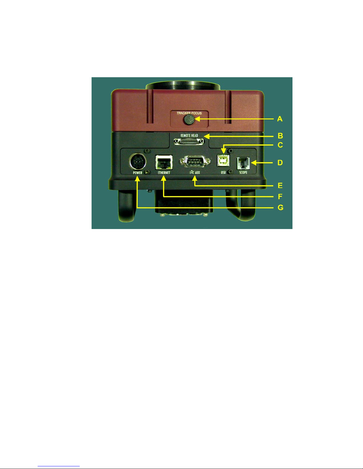
1.4. Connectors
[A] Tracking CCD Focus Adjustment
The built-in tracking CCD is set at the factory to be par focal with the imaging CCD
assuming a flat field. However, some optical designs produce enough curvature of field
to cause star images to be out of focus at the location of the tracking CCD. In this case
you may wish to adjust the focus of the tracking CCD. The available adjustment is +/-1.5
turns which corresponds to approximately +/- 1.5mm of focal plane shift for the tracking
CCD. To reset the adjustment to the nominal position, turn the adjustment screw fully
clockwise until it stops then turn it back (counterclockwise) 1.5 turns.
[B] Remote Guide Head Port
This miniature 25-pin connector is for attaching the optional remote guiding head. The
remote guiding head contains a 16-bit, cooled, low-noise, KAI-340S guiding CCD
identical to the guiding CCD built-in the camera. It draws its power from the main
camera and is controlled by the same software that controls the internal guider. This
option allows the use of either the internal or the remote guiding CCD for self-guiding
during long exposures. It has its own shutter for dark frames
[C] USB Port
Connect to your computer using a standard 14’ USB cable. If your computer must be
more than 14’ from the camera we recommend an active extension for short
distances
9
 Loading...