

Sbig STV User Manual

Operating Manual
STV
Video Camera and Autoguider
PRICE $10.00
Santa Barbara Instrument Group
147-A Castilian Drive
Santa Barbara, CA 93117
Phone (805) 571-7244 ♦ Fax (805) 571-1147
sbig@sbig.com ♦ www.sbig.com

Santa Barbara Instrument Group
147-A Castilian Drive
Santa Barbara, CA 93117
PHONE (805) 571-7244
FAX (805) 571-1147
Note: This equipment has been tested and found to comply with the limits for a Class B digital
device pursuant to Part 15 of the FCC Rules. These limits are designed to provide reasonable
protection against harmful interference in a residential installation. This equipment generates,
uses, and can radiate radio frequency energy and if not installed and used in accordance with the
instructions, may cause harmful interference to radio communications. However, there is no
guarantee that interference will not occur in a particular installation. If this equipment does
cause harmful interference to radio or television reception, which can be determined by turning
the equipment off and on, the user is encouraged to try to correct the interference by one or more
of the following measures:
• Reorient or relocate the receiving antenna.
• Increase the separation between the receiver and the equipment.
• Connect the equipment into an outlet on a circuit different from that to which the
receiver is connected.
• Consult the dealer or an experienced radio/TV technician for help.
Changes or modifications not expressly approved by the party responsible for compliance could
void the user's authority to operate the equipment.
Also note that user must use shielded interface cables in order to maintain product within FCC
compliance.
STV Manual
Second Printing
May 2000

Table of Contents
CHAPTER 1. INTRODUCTION ........................................................................................................................ 1
SYSTEM REQUIREMENTS ............................................................................................................................... 2
SYSTEM OVERVIEW ......................................................................................................................................... 2
CHAPTER 2. ASSEMBLY ............................................................................................................................... 3
CABLE CONNECTIONS ................................................................................................................................... 3
SYSTEM ASSEMBLEY ..................................................................................................................................... 4
FOCAL REDUCER ASSMEBLY ...................................................................................................................... 5
eFINDER ASSEMBLY ........................................................................................................................................ 5
OTHER ACCESSORIES ..................................................................................................................................... 6
CHAPTER 3. QUICK START ......................................................................................................................... 6
BASIC IMAGING ............................................................................................................................................... 7
BASIC AUTOGUIDING ...................................................................................................................................... 7
CHAPTER 4. CONTROL PANEL FUNCTIONS ........................................................................................... 8
CONTROL PANEL FUNCTIONS ...................................................................................................................... 8
Video Screen ... .................................................................................................................................... 8
Monitor Button .................................................................................................................................... 8
Image Button ....................................................................................................................................... 9
Focus Button ....................................................................................................................................... 9
Calibrate Button .................................................................................................................................. 9
Track Button ........................................................................................................................................ 9
Display / Crosshairs Button ................................................................................................................ 9
File Ops Button ................................................................................................................................... 9
Alphanumeric Display ........................................................................................................................ 9
Parameter Button ................................................................................................................................ 9
Value Button ....................................................................................................................................... 9
Left-hand Rotary Knob ....................................................................................................................... 9
Right-hand Rotary Knob ...................................................................................................................... 9
Interrupt Button .................................................................................................................................. 9
Setup Button ........................................................................................................................................ 9
VIDEO SCREEN APPEARANCE ........................................................................................................................ 10
CHAPTER 5. OPERATION ............................................................................................................................... 12
POWER UP ........................................................................................................................................................... 13
Setting the Date / Time ........................................................................................................................ 13
SETUP .................................................................................................................................................................... 14
Date/Time ............................................................................................................................................ 15
CCD Temperature .............................................................................................................................. 15
Grid .................................................................................................................................................... 16
Night Vision ........................................................................................................................................ 16
Filter .................................................................................................................................................... 16
Units ................................................................................................................................................... 16
Focal Length ....................................................................................................................................... 16
Aperture Diameter .............................................................................................................................. 16
Telescope ............................................................................................................................................ 16
Magnitude Correction ........................................................................................................................ 16
Site ...................................................................................................................................................... 16
Beep ..................................................................................................................................................... 16
Video Submenu ................................................................................................................................... 16
Video Mode ................................................................................................................................... 16
Date/Time ...................................................................................................................................... 16
Test Pattern ................................................................................................................................... 16
i

Gray Scale ..................................................................................................................................... 16
FOCUS ................................................................................................................................................................. 17
Focus Setup .................................................................................................................................................. 17
Focus Display ............................................................................................................................................. 17
Focusing Tips .............................................................................................................................................. 18
IMAGE ................................................................................................................................................................. 18
Image Setup ................................................................................................................................................. 18
Image Capture ............................................................................................................................................. 19
Exposure ...................................................................................................................................................... 19
Gain ............................................................................................................................................................. 19
Zoom ............................................................................................................................................................ 19
Dark Subtract .............................................................................................................................................. 19
Mode ............................................................................................................................................................ 19
Continuous ............................................................................................................................................... 19
Snap ........................................................................................................................................................ 19
Track & Accumulate ............................................................................................................................... 20
Mosaic (Lg) ............................................................................................................................................. 20
Mosaic (Sm) ............................................................................................................................................ 20
Best Sharp .............................................................................................................................................. 20
Best Peak ................................................................................................................................................ 21
Auto Grab ............................................................................................................................................... 21
Auto Grab Interval ..................................................................................................................................... 20
MONITOR ............................................................................................................................................................. 21
Monitor Setup .............................................................................................................................................. 21
eFinder ......................................................................................................................................................... 21
Optical Quality ............................................................................................................................................. 23
Drive Monitor (fast) ...................................................................................................................................... 23
Drive Monitor (slow) .................................................................................................................................... 23
Seeing Monitor (DIMM) ............................................................................................................................... 25
DISPLAY / CROSSHAIRS .................................................................................................................................... 26
FILE OPS ................................................................................................................................................................ 27
CALIBRATE .......................................................................................................................................................... 32
TRACK ................................................................................................................................................................. 34
INTERRUPT ......................................................................................................................................................... 36
CHAPTER 6. REMOTE OPERATION ............................................................................................................ 37
SOFTWARE INSTALLATION ........................................................................................................................... 37
STV REMOTE CONSOLE LAYOUT ................................................................................................................. 38
STV REMOTE CONSOLE PULL DOWN MENUS ........................................................................................... 38
File ............................................................................................................................................................... 38
Load STV Frame from disk ....................................................................................................................... 38
Save STV Frame to Disk in SBIG Format ................................................................................................. 38
Save Displayed Image in Bitmap Format ................................................................................................. 39
Receive and Automatically Save Images..................................................................................................... 39
Exit ............................................................................................................................................................ 39
Download .................................................................................................................................................... 39
Download Screen Image ........................................................................................................................... 39
Download All ............................................................................................................................................ 40
Abort Download ........................................................................................................................................ 40
Link .............................................................................................................................................................. 40
Set Baud Rate ............................................................................................................................................ 40
Establish Link ............................................................................................................................................ 40
Display .......................................................................................................................................................... 40
Adjust Contrast .......................................................................................................................................... 40
Auto Contrast ............................................................................................................................................. 40
Process ......................................................................................................................................................... 41
Flat Field ................................................................................................................................................... 41
Edit Data ...................................................................................................................................................... 41
Units ............................................................................................................................................................. 42
ii

APPENDIX A - SPECIFICATIONS ..................................................................................................................... 43
CAMERA SPECIFICATIONS .............................................................................................................................. 43
DC POWER JACK ................................................................................................................................................ 43
TELESCOPE PORT (AUTOGUIDER PINOUTS) ............................................................................................... 44
RS232 CONNECTOR / SERIAL CABLE ............................................................................................................. 44
SETTING JUMPERS FOR RELAY ADAPTER BOX ........................................................................................ 44
APPENDIX B - MAINTENANCE ....................................................................................................................... 45
REPLACING THE FUSE ...................................................................................................................................... 45
DISASSEMBLING/REASSEMBLING THE OPTICAL HEAD ......................................................................... 46
CLEANING THE OPTICAL WINDOW .............................................................................................................. 46
REPLACING THE DESICCANT ......................................................................................................................... 47
APPENDIX C - MONITOR MODES ................................................................................................................. 48
eFINDER MONITOR ........................................................................................................................................... 48
OPTICAL QUALITY MONITOR ........................................................................................................................ 49
DRIVE ACCURACY MONITOR ........................................................................................................................ 50
SEEING MONITOR ............................................................................................................................................. 51
APPENDIX D - OBTAINING A FLAT FIELD IMAGE ................................................................................... 53
APPENDIX E - ADJUSTING THE FILTER WHEEL ........................................................................................ 54
APPENDIX F - MENU STRUCTURE ............................................................................................................... 55
APPENDIX G - GLOSSARY ............................................................................................................................. 56
APPENDIX H - QUESTIONS & ANSWERS .................................................................................................... 59
INDEX .................................................................................................................................................................. 61
iii

Chapter 1. Introduction
The STV is a unique and versatile instrument. It is a highly sensitive, cooled, digital video camera
with exceptional abilities including the ability to autoguide and image without the need of a
computer. The STV will take and store digital images on board for download to a computer at a
later time. This makes the STV ideally suited for field use.
STV Features
Ø TC237 CCD with 656 x 480 Pixels and various binning modes
Ø Single Stage Thermoelectric Cooling
Ø Integral Filter/Shutter Wheel with Open, Closed and Filter positions
Ø Video Output to Internal and External Video Monitors
Ø Advanced 2 line x 24 Character Alphanumeric Display
Ø Fast Frame Rates (up to 10 frames per second)
Ø Built In Track & Accumulate (SBIG patent 5,365,269)
Ø 2 MB Flash memory for saving 14 images
Ø Remote Operation with STV REMOTE Software
Ø Digital Signal Processor (DSP) Powered for Highest Performance
Ø Standard T-Thread Front End (with screw in 1.25" nose piece)
Ø Telescope Port for Stand Alone (No Computer Required) Auto Guiding
Ø RS-232 Port for Remote Control and Image Download
Ø Optional 2 position Focal Reducer for 2X and 3X Reduction
Ø Optional C-Mount and Tripod Mount Accessories
Ø Optional Mini 4" Focal Length Telescope Tube for eFinder Operation
Ø Optional built-in 5" LCD Video Screen
What Can You Do With An STV?
Ø Rapidly Focus the System at Video Rates with the Focus Mode
Ø Adjust Focus Sensitivity with a Single Knob
Ø Take High Quality Images with Image Mode
Ø Continuous
Ø Snap shots
Ø Track & Accumulate
Ø Mosaics
Ø Auto Grab
Ø Save Images to Flash Memory with the File Ops Mode
Ø Download Images to PC for Offline Viewing and Processing
Ø Measure Images with the Display Mode
Ø Stellar Magnitudes
Ø Stellar Separations
Ø Autoguide Your Telescope with the Calibrate and Track Modes
Ø Measure Critical Seeing Parameters with the Monitor Modes
Ø Telescope PEC
Ø Optical System Quality
Ø Atmospheric Seeing
Ø Electronic Finder (eFinder)
1

System Requirements
______________________________________________________________________
The STV does not require a computer to operate. However, a computer can remotely control the
STV and digital images may be downloaded to a computer over a standard serial port. Remote
control and image transfers require that STV REMOTE software be installed on the host computer.
The minimum system requirements are:
IBM compatible PC running Windows 95/98
1.44MB floppy drive (for software installation)
256 color graphics display (or 16 bit color graphics for better image rendition)
Standard serial port (COM1 or COM2)
Recommended system requirements are:
True color (24 bit or 32 bit) graphics display for faster performance
External Video Monitor
System Overview
______________________________________________________________________
The STV is easy to use and you are encouraged to try all of its functions without fear of hurting the
camera. It is impossible to damage the STV by pressing any of the buttons on the control panel. If
you ever get lost in a menu and want to start over simply press the Interrupt button and begin again.
Most of the STV's functions are accessed in a similar way. In general, pressing a function button
once takes you to the setup menu for that function and pressing the same function button again
starts the particular function using the values you have entered in the setup menu. The STV will
remember the setup items as you last entered them. If you are repeating a function and you do not
want to make any changes in the setup items simply press the function button twice to initiate the
function using the old setup values.
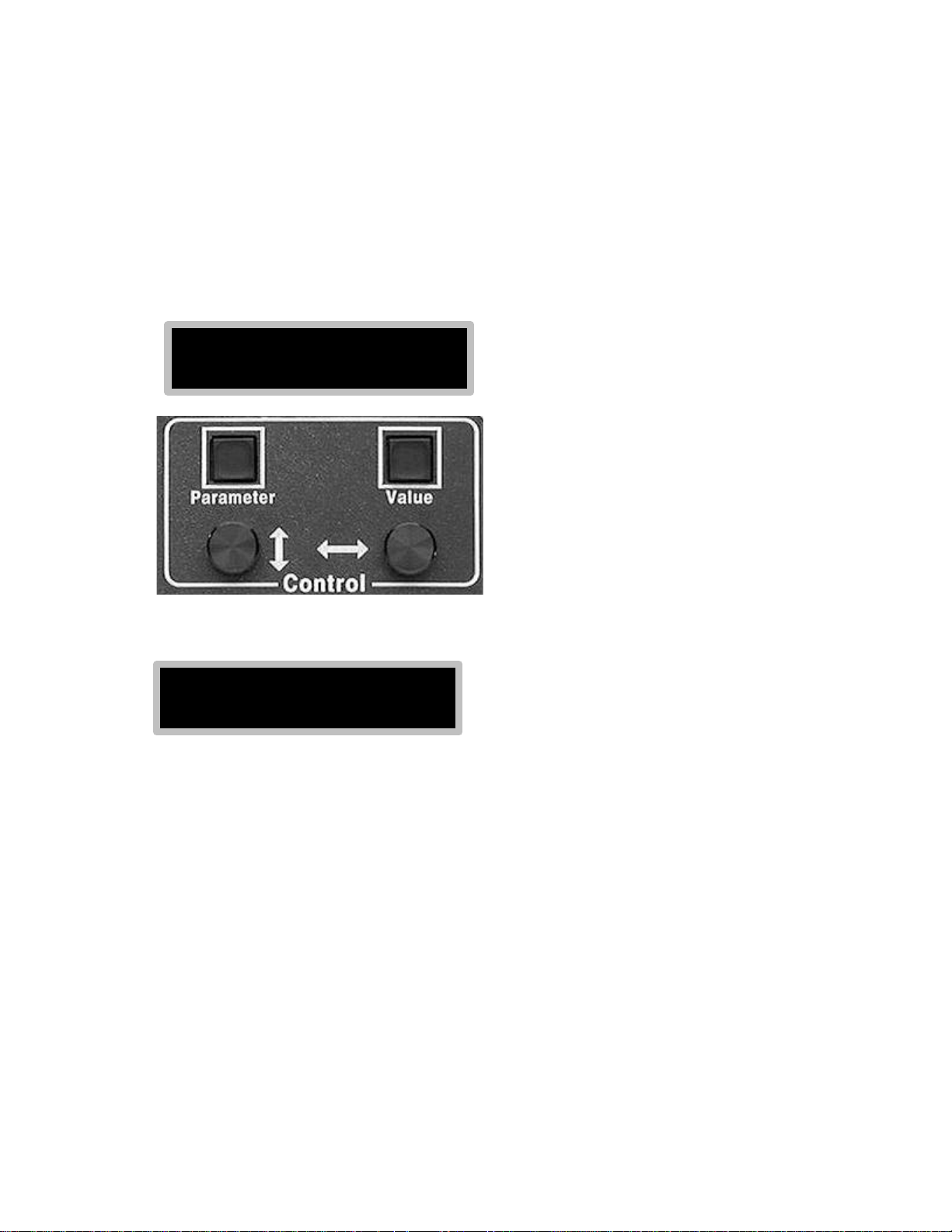
The control panel is laid out in such a manner as to make using the buttons as intuitive as possible.
For instance, menu items are generally displayed on the left-hand side of the alphanumeric display.
You can scroll through these items (parameters) by pressing the Parameter button located directly
under the left-hand side of the alphanumeric display. In some cases you may also scroll through
the menu items (parameters) by turning the rotary knob directly under the Parameter button. An
example of this is setting the Date and Time. By repeatedly pressing the Parameter button you
can scroll through the menu to select the items: Month, Day, Year, etc. For every menu item
(parameter) there is a value shown on the right-hand side of the alphanumeric display. Using the
Date as an example, after selecting from the menu item "Month," then you would chose a value for
this item by repeatedly pressing the Value button or turning the rotary knob directly under the
Value button. For the menu item "Month" the possible range of values is 1 to 12. If the current
month is January, you would select a value of 1.
2
Chapter 2. Assembly
Assembly of your STV is simple and straightforward. All of the cable connections are clearly
marked on the back of the STV chassis. It is recommended that power be connected last.
Important Safety Notes: Observe proper polarity if using 12VDC. Center pin is negative. The
STV head can be damaged if you connect or disconnect it with the power turned on. Do not
attempt to connect a head from an ST-237, ST-5C or any other camera in place of the STV head!
Severe damage will result and your warranty will be void.
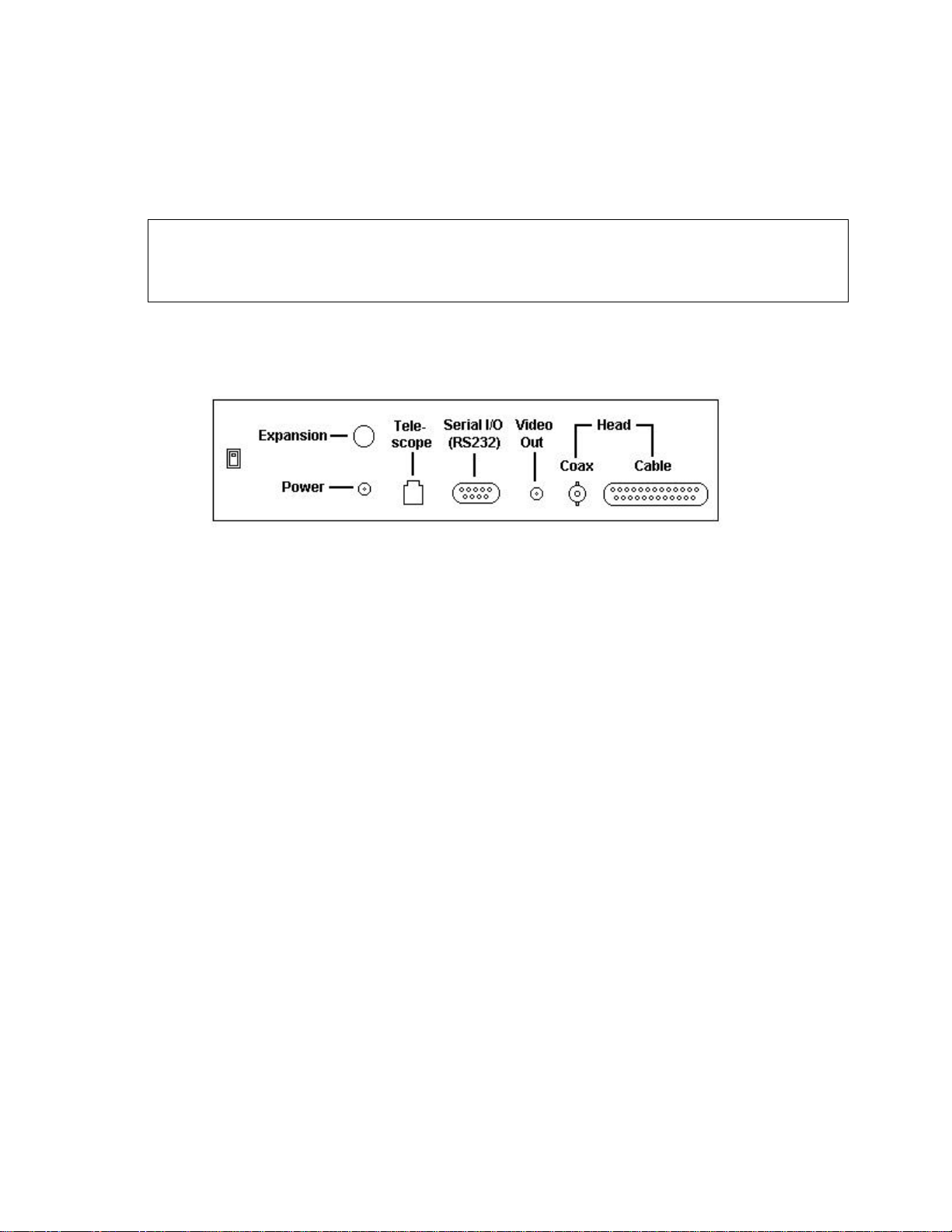
Cable Connections
______________________________________________________________________
1. The STV camera head has two cables that must be connected to the CPU box. Connect both the
DB25 Cable and the smaller BNC Coax plug to the connectors indicated under "Head" on the
back panel.
2. The Video Out plug on the back panel is for connecting the STV to an external video monitor
or VCR using commonly available video cable. The connector is a standard RCA type jack. The
external monitor must be equipped with a "Video In" connector.
3. The DB9 Serial I/O (RS232) port is for connection to a standard serial port (COM1 OR COM2)
on a PC using the supplied serial cable. While a computer is not necessary for the STV to function,
you may remotely control the camera from the computer and you may also download digital
images stored in the STV's internal memory to the computer. The Serial I/O may also be used for
upgrading the STV firmware as updates become available.
4. The RJ11 Telescope jack is the autoguider output from the STV. The STV contains internal
mechanical relays similar to the ST-4 making it suitable for any autoguiding application without
the need of a relay adapter box. A telescope interface cable (TIC) is supplied with the STV that
will plug directly into the "CCD" port on many common telescope mounts such as the LX200,
Ultima, Losmandy and others. If your particular telescope drive does not accept the relay cable
supplied, please refer to Appendix A, page 44, for the relay pinouts of the STV. This information
may be used to construct a custom cable.
5. The Power plug is for receiving 12VDC to operate the STV (Note: center pin is negative and
outside is positive). You may use the supplied wall transformer or you may power the STV from a
battery source. If you are powering the STV from a source other than the wall transformer please
refer to Appendix A, page 43, for the required specifications.
6. The Expansion slot is not used at this time.
3
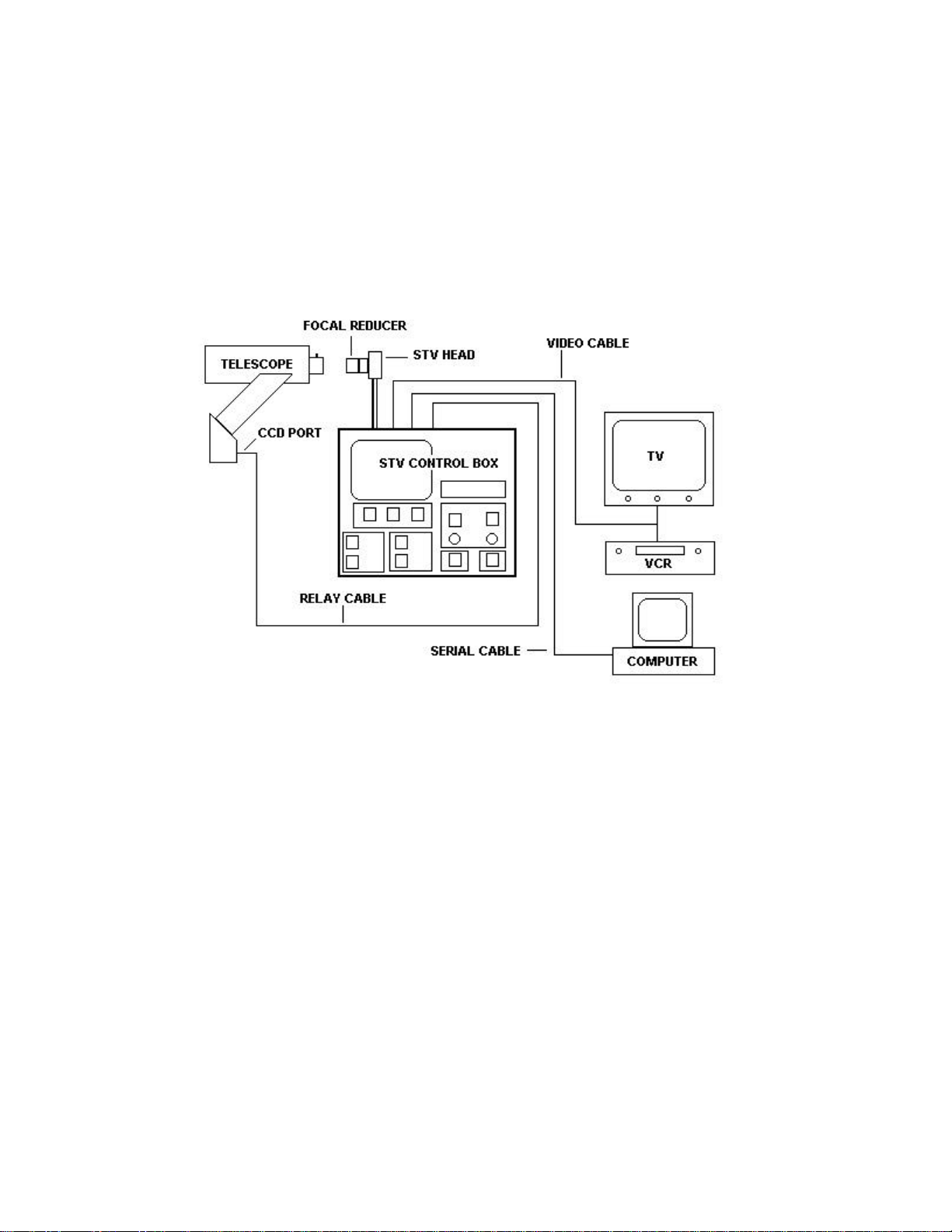
System Assembly
______________________________________________________________________
A number of external connections may be made to increase the versatility of the STV. Some or all
of these external connections may be made at the same time. For instance, you may connect the
STV to a remote computer and an external video monitor. If connected to a telescope, you can use
the STV as a stand alone autoguider or you may control the guiding functions remotely from a PC
or laptop while viewing the video signal on the external video monitor.
The connection to a telescope is for autoguiding only (e.g., not GOTO functions). For remote
telescope GOTO control you will need a software package such as TheSky from Software Bisque.
Typically remote telescope GOTO control is handled over the telescope's RS232 port. You should
not confuse this with the RS232 port on the STV and attempt to connect the STV and telescope's
RS232 ports. The STV (like all other autoguiders) connects to a telescope by way of a "CCD" port
or an "Autoguider" port. In some cases (e.g., Losmandy) the connection is made using the same
port as the telescope's hand controller. Please consult with your telescope's manual or the
manufacturer for the proper autoguider input port for your telescope.
Most commercial telescopes manufactured recently have an RJ11 phone type jack available as an
input port for autoguiders. If your telescope has a different plug for an autoguider, please refer to
the Appendix A, page 44, of the manual for pin outs of the STV's telescope jack so that you can
make your own relay cable. Also, note that on the LX200 series and some others, the autoguider
port is labeled "CCD." Unfortunately some of these same telescopes also use an RJ11 type plug for
serial communications to a computer for remote control. These auxiliary ports on the telescope
look identical to the autoguider ports but they may be labeled RS232 or AUX instead of CCD.
Meade ETX models and Celestron Nextstar models have RJ11 type jacks for RS232
communications only, not autoguider input. If you are unsure if your telescope supports an
autoguider, please consult with the telescope manufacturer.
4
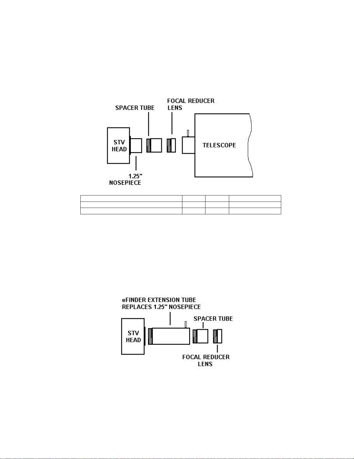
Focal Reducer Assembly
_____________________________________________________________________
An optional custom focal reducer is a recommended accessory for the STV. This focal reducer
also doubles as a wide field finder/autoguider lens. When used with the supplied spacer tube, this
focal reducer will reduce an f/10 system to approximately f/3.75.
Focal ratio of parent system F/14 F/10 F/6.3
Resulting focal ratio without spacer tube F/8 F/5.95 F/3.75
Resulting focal ratio with spacer tube F/5.25 F/3.75 Not recommended
eFinder Assembly
______________________________________________________________________
The focal reducer lens is also designed to work as an f/4 wide field lens of ~100 mm focal length
when placed at a distance of about 4" from the CCD chip. In this configuration the STV works
exceptionally well as an electronic finder ("eFinder") scope. A special tube assembly is provided
that will place the lens at approximately the correct distance. The extension tube has a set-screw at
the objective end that allows for focus adjustment by sliding the lens in and out until best focus is
achieved. The eFinder extension tube assembly replaces the nosepiece when using the lens as a
wide field objective. In this configuration, the STV may also be used as a piggyback autoguider
without the need of a separate guide scope. The tracking accuracy of the STV with the eFinder
lens assembly is better than 1 arc second.
5
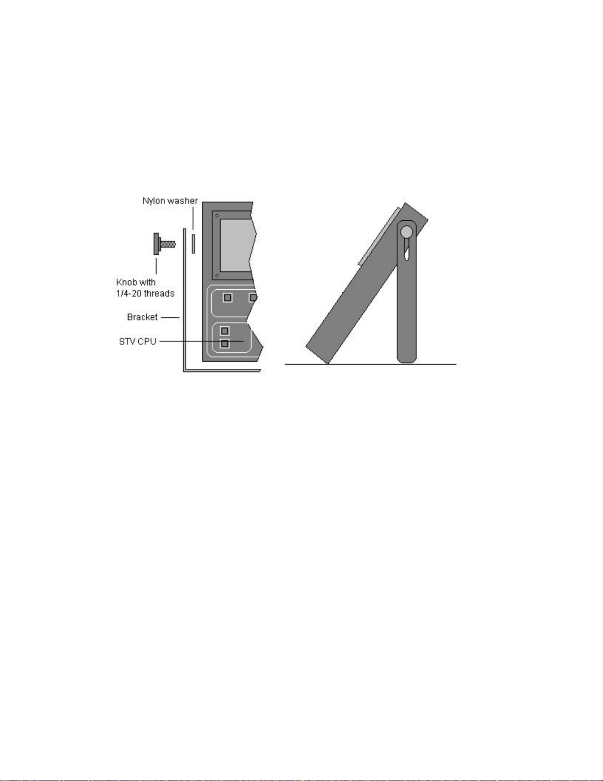
Other Accessories
______________________________________________________________________
The STV comes with a large "U" shaped bracket that can be used as carrying handle or a support
for tilting or standing up the STV CPU box. You may find this helpful in placing the built-in 5"
LCD video screen at the optimum viewing angle. The bracket is supplied with 2 nylon washers
that should be inserted between the bracket and the case to protect the case from scratches. The
bracket is attached to the case with two supplied 1/4-20 threaded knobs.
Recommended Accessories for the STV from SBIG:
Ø Custom Focal Reducer and eFinder Tube assembly.
Ø T-thread to C-thread adapter (for attaching video camera lens).
Ø CLA5 Camera lens adapter (for attaching a 35mm camera lens).
Ø Tripod foot (for attaching STV head directly to tripod or to piggy back mount).
Ø 12VDC power cord (with alligator clips and cigarette lighter adapter).
Ø Hard carrying case with custom cut foam for STV.
Ø CCDOPS for Windows 95/98/NT.
Other Recommended Accessories for the STV:
Ø External high resolution B&W video monitor
Ø Laptop or PC for remote control
Ø Marine deep cycle battery for extended field operation
6

Chapter 3. Quick Start
If you are one of those individuals who think that detailed instruction manuals are for everyone
else, this section is for you!
Basic Imaging
______________________________________________________________________
1. Attach the camera head and other cables as indicated on the back panel of the control box, plug
in the power cord from the wall transformer and turn on the STV. Set the Date/Time. Go to the
Setup menu and set the telescope focal length and aperture.
2. Insert the STV head into a telescope or attach the eFinder lens supplied with the STV and point
it at something in the sky that is not too bright (The moon may be too bright without the lunar filter
item selected in the Setup menu).
3. Press the Focus button twice and adjust the exposure time with the rotary knobs until you can
make out light and dark areas in an image. Focus the telescope or lens. Toggle the zoom mode by
pressing the Parameter button. Toggle the frame size by pressing the Value button.
4. Press the Image button once and set an exposure time by using the left-hand rotary knob to
select "Exposure" from the menu and use the right-hand rotary knob to pick the value in seconds.
Press the Image button again to start taking images. Adjust the brightness and contrast with the
rotary knobs.
5. Press the Image button again to go back to Image setup if you want to increase or decrease the
exposure time. You can also go through the Setup menu to find the "Filter" item so you can try it
on bright things like the moon.
6. When you see something you like - press the Display button. Adjust the Brightness and
Contrast with the rotary knobs or press the Parameter button for Auto Contrast. If you want to
save the image press the File Ops button and select SAVE from the menu. Press the Value button
under the small arrow and you will see the SAVE submenu. For a quick reference to all the menu
items in the STV see Appendix F, page 55.
Basic Autoguiding
______________________________________________________________________
1. Do Basic Imaging steps 1-3. Make sure you have properly entered the focal length in the Setup
menu. The STV uses this information to choose the calibration time. Mount the STV head
piggyback on your telescope with the eFinder lens assembly attached. Connect the relay cable to
your drive and press the Calibrate button - use auto mode.
2. After calibration is done, press the Guide button.
3. Repeat above or press any button you like to see what happens until you decide to read the rest
of the manual! Have fun!
7
Chapter 4. Control Panel
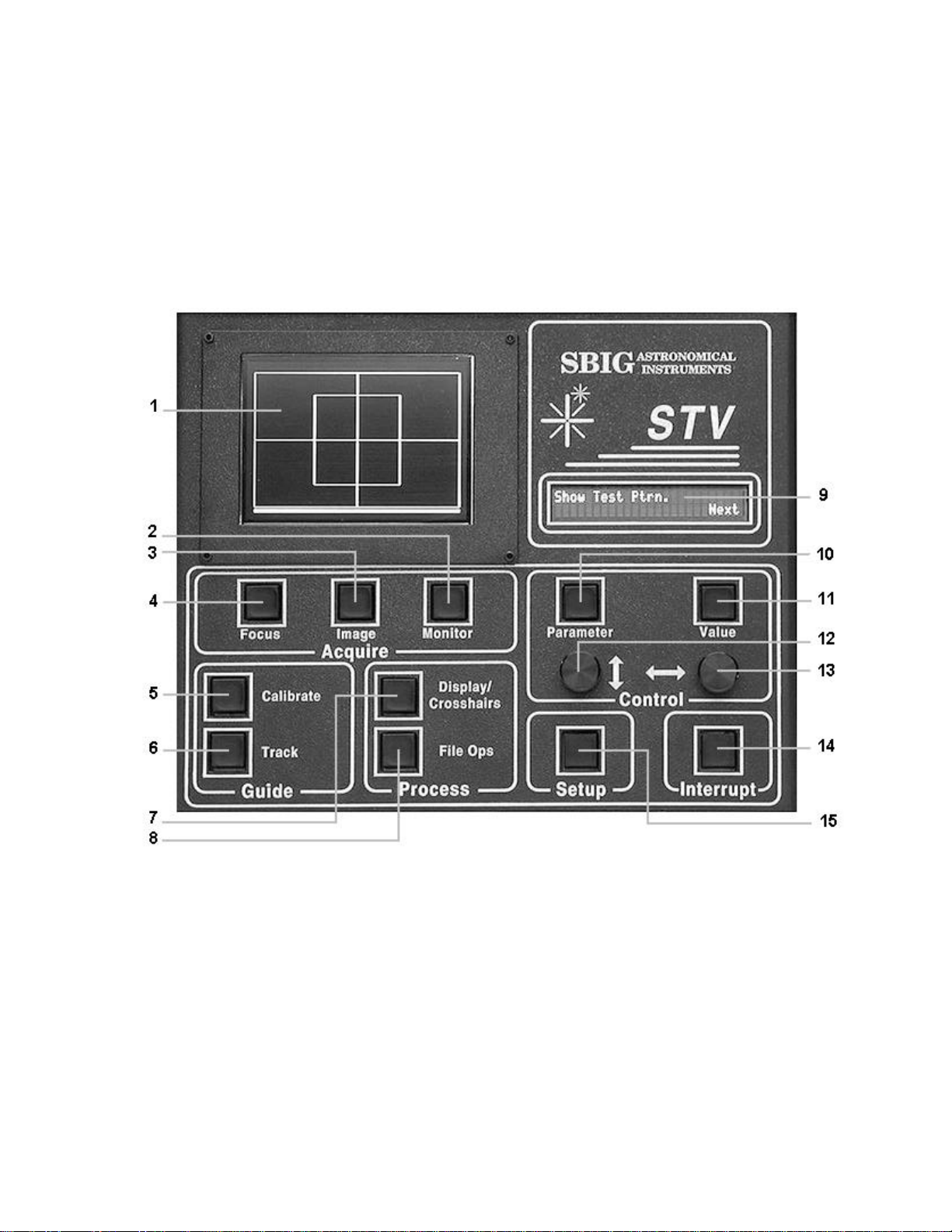
The control panel of the STV labels each of the function buttons as shown in the figure below. The
upper left quadrant of the control box holds the optional built-in 5" LCD video screen (shown here
with the test pattern activated). The upper right quadrant of the control box under the SBIG logo
contains a 2 line by 24 character vacuum florescent alphanumeric display. The lower left and
lower right quadrants contain the control buttons used to activate and toggle through the STV menu
functions.
Control Panel Functions
______________________________________________________________________
A brief description of the STV control panel buttons and displays is outlined below. For a more detailed
description of each function please refer to Chapter 5 of the manual.
1. Optional built-in 5" LCD video screen. An external TV or VCR may be used instead of or in
addition to the built-in video screen. The video screen area contains information as well as the video
image. The diagram on page 10 shows the layout and identification of the STV's video output.
2. Monitor button. Press once to activate the Monitor Setup Menu. Press again to enter one of the
five Monitor modes: eFinder, Optics, Drive (slow), Drive (fast) and Seeing. See page 21 for details.
8

3. Image button. Press once to activate the Image Setup Menu. Press again to enter Image mode. In
the Image Setup Menu you may select various Image modes such as Continuous, Snap, Track &
Accumulate, etc. See page 18 for details.
4. Focus button. Press once to activate the Focus Setup Menu. Press again to enter Focus mode.
See page 17 for details.
5. Calibrate button. Press once to activate the Calibration Setup Menu (auto or full menu). Press
again to activate a calibration sequence before autoguiding. The STV automatically calculates the
exposure time and grabs an image. The STV automatically estimates the amount of move to make and
then moves in each of 4 directions and measures the results. If enough stars are seen in the original
image, the STV will mark up to eight bright stars. If the STV cannot find 8 stars in the original frame, it
will mark as many as it can detect. After each move, the STV will check to see if a majority of the stars
marked on the previous frame are present. If so, it will continue to calibrate until done. The process
takes a couple of minutes. See page 32 for details.
6. Track button. Press to start autoguiding after a successful calibration sequence. See page 34 for
details.
7. Display / Crosshairs button. Press once to activate the Display / Crosshairs Mode anytime there is
an image on the video screen. Entering Display Mode freezes the video image and places a scale bar at
the bottom of the video screen. The rotary knobs will adjust the brightness and contrast of the frozen
image. Press the Value button to activate and toggle the cross hairs. When the cross hairs are active
the rotary knobs are used to adjust the position of the cross hairs on the image for measuring stellar
magnitudes and angular separation. See page 26 for details.
8. File Ops button. Press once to enter the File Operations menu where you can Save, Recall and
Erase images as well as download images to a remote computer. See page 27 for details.
9. Alphanumeric display. This 2 line x 24 character vacuum fluorescent display provides menu and
other information during operation of the STV. The information changes depending on the mode you
select. See the particular mode section for details.
10. Parameter button. Performs several different functions depending on the mode. Typically it is
used to toggle through items in setup menus or to change the zoom level in image mode. See the
individual mode section for details.
11. Value button. Performs several different functions depending on the mode. Typically it is used to
select a value for a menu item or to toggle the frame size in image mode. See the individual mode
section for details.
12. Left (up-down) rotary control knob. Performs several different functions depending on the mode.
It often mirrors the Parameter button for scrolling through menu items (e.g., selecting the item
"Exposure" in the Image Setup menu). Changes the Brightness in image mode. See the individual mode
section for details.
13. Right (left-right) rotary control knob. Performs several different functions depending on the
mode. It often mirrors the Value button for scrolling through values to be assigned to menu items (e.g.,
selecting "10 seconds" as the exposure time in Image Setup menu). Changes the contrast in image
mode. See the individual mode section for details.
14. Interrupt button. Press once anytime to stop whatever is in progress and freeze the image. The
alphanumeric display reverts to the same display as on power up. Press Interrupt again to blank the
video screen. Holding down Interrupt while turning on power to the STV prepares the camera to receive
a firmware update via the RS232 port. See page 36 for details.
15. Setup button. Press once to activate the STV set up menu. Use the Parameter and Value buttons
or the rotary knobs to scroll through the setup menu items and the values assigned to each item. See
page 14 for details.
9
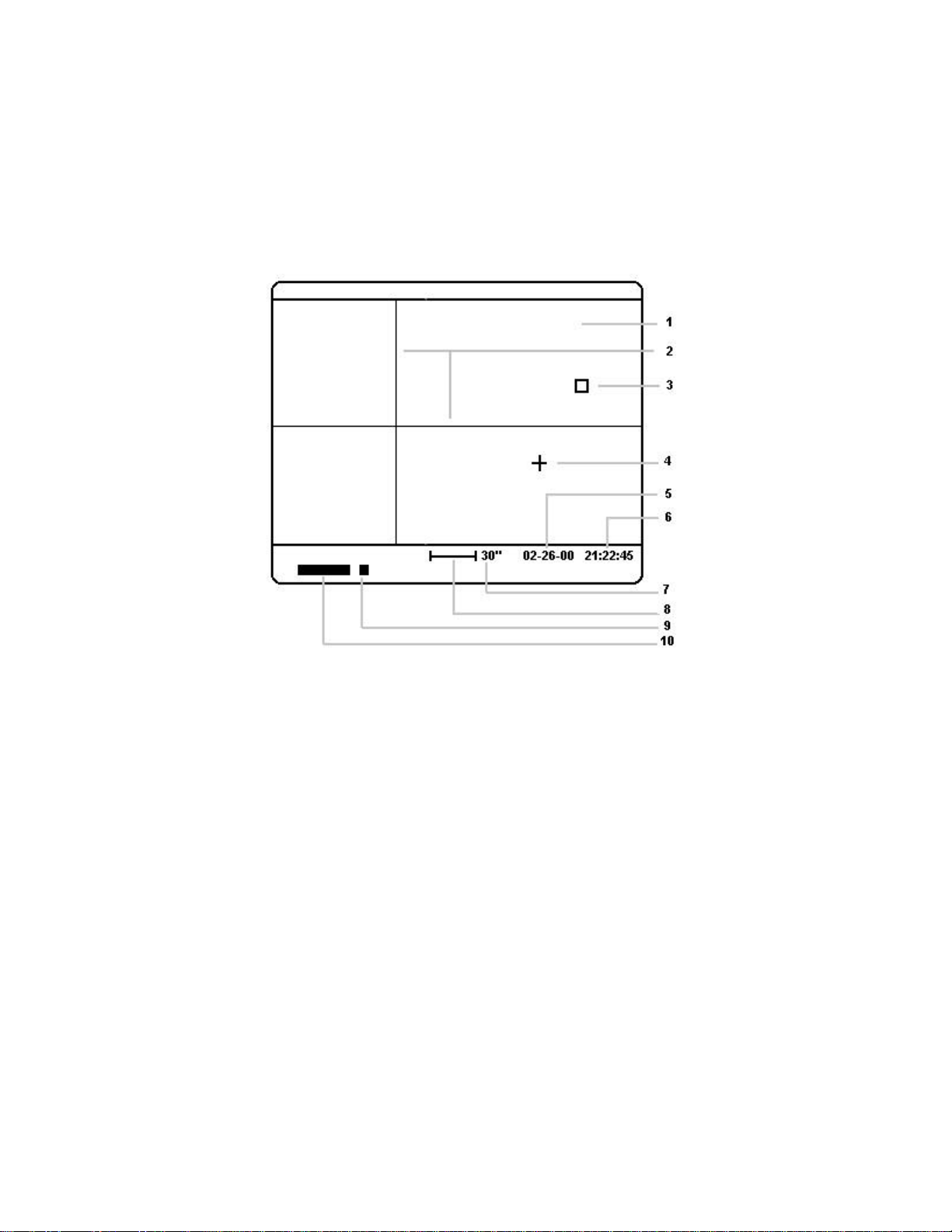
Video Screen Appearance
______________________________________________________________________
The video output of the STV often contains data as well as the video picture. For instance, if the
Date / Time function is set to "on" in the setup menu then the information will automatically be
displayed under the video image whenever the STV is in Image mode. The information displayed
on the video screen changes depending on the mode you select (next page):
1. Video image area (see page 12).
2. Adjustable Crosshairs.
3. Small box marks area of image you select with crosshairs as the background when making stellar
magnitude measurements or separation measurements.
4. Small cross marks the first star or location you select when making stellar magnitude measurements or
separation measurements.
5. Date displayed below image area in Image Mode and Idle Mode.
6. Time displayed below image area in Image Mode.
7. Value in arc seconds or arc minutes of image scale bar displayed in eFinder mode and Display mode.
8. Image scale bar displayed in eFinder mode and Display mode. Scale is based on focal length entered in
set up menu and the zoom level currently displayed.
9. Moving cursor travels across bottom of screen from left to right taking one step after each exposure in
Focus, Image and Monitor modes.
10. "Gas gauge" indicator showing progress of single exposures of 3 seconds or longer. For shorter
exposures this indicator remains solid.
10
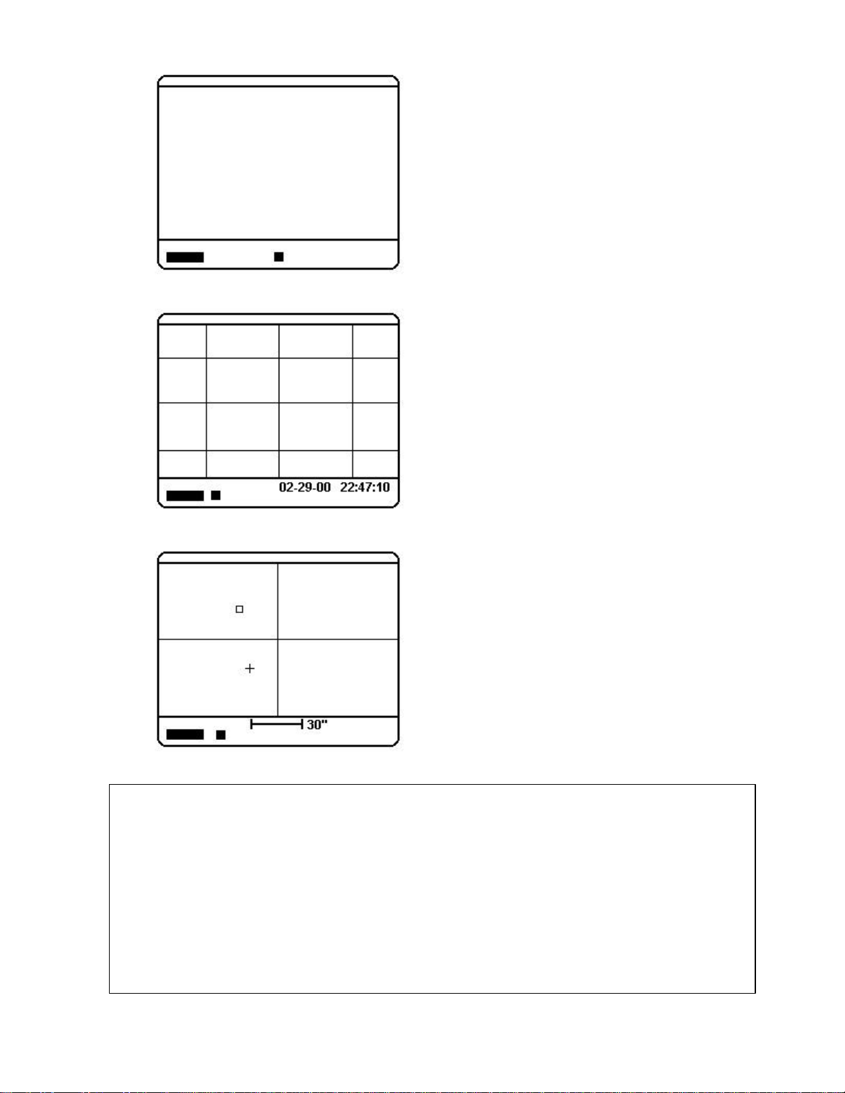
Focus Mode:
Display / Crosshairs / eFinder Mode:
Only the exposure indicators are displayed in focus
mode.
The "gas gauge" indicator remains solid and the small
cursor moves to indicate continuous exposures in
progress. The longest exposure possible in Focus
mode is 2.5 seconds with the zoom level set to
Normal (see Tech Note below).
Image Mode:
The date and time are displayed in addition to the
exposure indicators. The grid may be turned on or off
in the set up menu (default is off).
The "gas gauge" indicator shows exposures in
progress for exposures of 3 seconds or longer. The
small cursor moves one step from left to right after
each exposure. Exposure times from .001 to 600
seconds are possible in Image mode.
TECH NOTE - Exposure Times and Zoom Level: The STV has three electronic zoom levels: Normal, Zoom and
Wide. When the zoom level is set to Normal, the central 640x400 pixels of the CCD are binned 2x2. When the
zoom level is set to Zoom, the central 320x200 pixels are displayed unbinned (1x1). When the zoom level is set
to Wide, the entire array of 656x480 pixels is binned 3x3. Binning pixels increases the sensitivity as a function of
the area of the pixel. What this means is that if the exposure time seems about right when you have the zoom
level set to Normal, and you then switch the zoom level to Zoom or Wide, the sensitivity changes as well. To
compensate for this fact, the STV automatically adjust the exposure times when you switch between zoom levels
to equalize the sensitivity. This keeps the image brightness on the video screen about the same when you toggle
between zoom levels. Throughout this manual where reference is made to exposure times, operation in Normal
mode is assumed. For instance, in Focus mode the maximum exposure time allowed is 2.5 seconds with the
zoom set to Normal. However, if you set the zoom level to Wide the maximum time is 2.2 seconds (.88X Normal)
and if you set the zoom level to zoom the maximum time is 5.0 seconds (2X Normal).
In Display mode the video image and the exposure
indicators are frozen. The adjustable crosshairs may be
turned on or off. The small box marks the location you
select as the background and the small crosshair marks
the location you select as the first star for stellar
magnitude and separation measurements.
In eFinder mode the video screen looks the same as
crosshairs mode with adjustable crosshairs except that
the image is continuously updating. The exposure
indicators operate as they do in Image mode
11
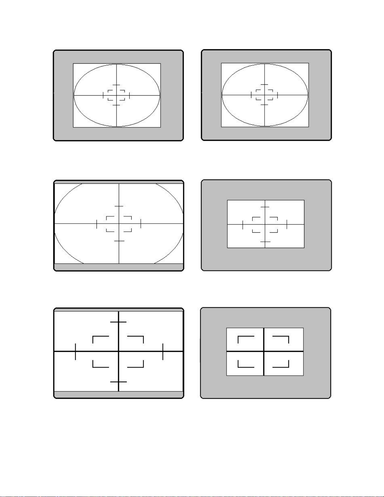
Wide + Full: The entire 656x480 pixels are
dim objects.
binned 3x3 and displayed in a window in the
center of the video screen. This gives the
widest field of view and is the most sensitive
mode. Best for imaging large dim objects
Wide + Partial (focus only): Same as Wide +
Full except every other line is displayed every
other frame. This increases the update rate by
approximately 2X. Best for finding and centering
Normal + Full: The central 640x400 pixels are
binned 2x2 and displayed to fill the video screen
horizontally. Good balance of sensitivity and
resolution. Good mode for galaxies.
Zoom + Full: The central 320x200 pixels are
displayed unbinned (1x1) to fill the video screen
horizontally. This mode has the lowest sensitivity
and highest resolution. Best for moon and planets.
Normal + Partial (focus only): Same as Normal
+ Full except only the central 60% of the image
is displayed. This increases the update rate by
about 2X.
Zoom + Partial (focus only): Same as Zoom +
Full except only the central 60% of the image is
displayed. This increases the update rate by
about 2X. Best mode for critical focusing.
12

Chapter 5. Operation
DATE/TIME SETUP
This Chapter describes the operation of the STV in detail.
Power Up
______________________________________________________________________
When you first turn on the power to the STV, the camera will initialize, flash the ROM version
and then you will see a display similar to this:
Filter=Open Please set
+12.2c ♦♦ 70% Date/Time
The diamond shaped symbol will blink at first indicating that (a) the TE cooler is active and (b) the
STV is seeking the optimum operating temperature. The STV will automatically set an optimum
operating temperature according to the ambient temperature. Once the temperature of the CCD has
stabilized the diamond symbol will stop blinking.
The information format on the display above is divided into a left and right section. Generally this
corresponds to menu items and values that are adjusted by pressing the Parameter and Value
buttons immediately below the display or by scrolling through the menus with the rotary knobs
located just below the Parameter and Value buttons. Setting the date and time demonstrates the
relationship of the buttons and knobs just below the display to the information and menu items
shown on the display. In the display shown immediately above, the left section of the display
shows the position of the internal filter wheel, the CCD temperature and the percent of power the
TE cooler is drawing in order to or maintain the temperature of the CCD. You can override this
automatic temperature setting in the main SETUP menu if you wish. On the right of the display
you are prompted to set the current date and time. The STV will remember the date and time the
STV was last used but it does not have an internal battery operated clock so you must set this each
time you power up. You can ignore the date and time setup and the STV will function normally
but your images will not have a correct date and time stamp on them. You can set or change the
date and time whenever you like by pressing the SETUP button and entering the setup menu. To
set the current date and time after power up hit the Value button under the words "Please set
Date/Time" and you will enter the DATE/TIME SETUP menu similar to this:
Month 1
Date / Time Setup Tips:
Use the left (Parameter) button or the left control
knob to scroll up and down through the menu items:
Month, Day, Year, Hour, Minute, Second. Use the
right (Value) button or control knob to scroll left and
right through the values for each of the menu items.
When you have entered all the current information
down to the second the display will prompt you to
Sync Time Do It! At this point you can press the
Value button to sync the time to the nearest second
based on a reference source such as WWV, the
Phone Company or an external clock.
13

When you have entered all of the date and time information you will see the following display:
DATE/TIME SETUP
SYNC TIME Do it!
Hit the Value button to synchronize the time to an external source. The STV will set its clock and
after a second or two show a display similar to this:
Filter=Open 2/01/2000
- 3.4c ♦♦ 70% 20:24:12
You will note that this is similar to the display appearance at power up but now the date and time
are shown and the temperature of the CCD will probably be lower than when you first turned on
the power.
Setup
______________________________________________________________________
You can enter the SETUP menu at any time by pressing the Setup button on the STV control panel.
The Setup menu contains a number of items in addition to the date and time. The STV will
remember some of the items the next time you power up the camera but the date and time
information will be saved only as of the time the camera was turned off. This is why there is also a
separate prompt to enter the date and time at power up. The items contained in the Setup menu are
as follows:
MAIN MENU VALUES
Date/Time Set month, day, year, hour, minute, second
CCD Temperature Set temperature to a given value greater than -50 (degrees C).
Grid On / Off (displays a grid overlay in image mode for manual guiding)
Night Vision On / Off (turns the video image predominantly red)
Filter Yes / No (rotates an internal filter over the CCD for ~20x attenuation of light)
Units Inches / cm
Focal Length Enter your scope's focal length (0.01 to 600)
Aperture Diameter Enter your scope's aperture diameter (0.01 to 600)
Telescope Refractor / Reflector (a Schmidt-Cassegrain is a reflector)
Magnitude Corr. Enter correction factor for calibration of magnitudes (+5.0 to -5.0)
Site Enter site ID number from 1 to 255 for inclusion in the image header
Beep On / Off
Adjust Filter Adjust the threshold value for the filter wheel opto sensor
Video „ [takes you to the VIDEO SETUP MENU]
VIDEO MENU VALUES
Mode NTSC / Internal PAL / External PAL / Off (set video format or turn it off)
Date/Time On / Off (turns the date/time display on the video screen on or off)
Test Pattern „ [displays a test pattern for adjustment of an external video display]
Gray Scale „ [displays a gray scale for adjustment of an external video display]
14
In the same way that you set the Date/Time when you powered up the STV, once you have pressed
the Setup button, you can scroll through the setup menu items by pressing the Parameter button or
by turning the rotary know directly under the Parameter button. Likewise you may select or
change the value for any given men item by pressing the Value button or by turning the rotary
knob directly under the Value button.
For illustration let us assume you wish to use the Night Vision Mode for the video display. You
press the Setup button to enter the setup mode and then scroll through the menu items using the
Parameter button or the rotary knob directly under the Parameter button until you see the
following display:
STV SETUP
Night Vision Off
You would then press the Value button under the word "Off" or turn the rotary knob directly under
the Value button until the display reads:
STV SETUP
Night Vision On
Notice that repeatedly pressing the Value button or turning the rotary knob directly under the
Value button toggles the Night Vision mode On and Off. There is no additional step required to
"save" the setup values because the STV automatically saves the last value entered until you
change it. When you have set a particular value in the setup mode, you may simply exit the setup
mode by pressing any other button on the STV control panel.
Use the same procedure to select and set any item in the Setup menu:
Date / Time: Set or change the date and time. You are also prompted to enter this information at power
up of the STV (the STV does not have an internal battery operated clock so the date and time
information must be entered whenever you power up the STV CPU). The STV will remember the last
date and time you used the STV so it is usually only necessary to update the day and time when setting
up for an imaging session. If you leave this information blank, the STV will operate normally but the date
and time information will not be displayed on the video screen and there will be no date or time of
observation recorded in the headers of saved images. It is not necessary to set the date or time when
using the STV as an autoguider only.
CCD Temperature: The STV will automatically pick an operating temperature when you power up the
CPU. The STV will attempt to run at the lowest temperature it can achieve using 70% power to the TEC
(thermoelectric cooler). If the head warms up during the imaging session and the TE cooler power
15

approaches 100% you should re-set the temperature to a higher number so that the % figure remains
about 70 to 80. If the night cools off you can set the temperature to a lower number.
Grid: When set to "on" the STV will overlay a grid on the video image when the STV is in Image Mode.
The grid is three vertical and three horizontal lines, making 9 intersections on the video screen. These 9
intersections make handy cross hairs for manual guiding. Default setting is "off."
Night Vision: When set to "on" the video image is colored red. Default setting is "off."
Filter: There is an internal filter wheel in the STV head containing a green filter. When this menu item is
set to "on" the filter is rotated into place over the CCD. The green filter is useful for imaging the moon
as it attenuates the light by about 20X. You should set this to item to "on" if you are imaging the moon
and the image is saturated at the shortest exposure time. The filter is also useful for making more
accurate measurements of stellar magnitudes because it passes light in the middle of the visual
spectrum. The filter position is indicated on the alphanumeric display at power up. Also, since the filter
greatly attenuates the light reaching the CCD, a reminder is displayed if you attempt to take images
longer than 2 seconds with the filter in place. Default setting is "open." [Note: Filter glass causes a
slight shift of focus. If you focus first and then set the Filter to "On" you should re-focus the camera].
Units: Set this to "inches" or "centimeters" at your discretion. When you enter values for Focal Length
and Aperture this item dictates whether the Focal Length and Aperture values are in inches or
centimeters. Default setting is "inches."
Focal Length: Enter the focal length of your telescope in inches or centimeters (depending on the
"Units" selected in the previous menu item). The focal length of your telescope is calculated by
multiplying the diameter of the aperture by the f/ratio. For example, an 8" f/10 telescope usually refers to
a telescope that has an aperture of 8" and a focal ratio of 10. In this example the focal length is 8" x 10 =
80". Note that a 6" f/8 telescope and an 8" f/6 telescope both have the same focal length (48 inches).
Aperture Diameter: Enter the diameter of your telescope's primary objective (lens or mirror).
Telescope: Select either reflector or refractor. Many catadioptric telescopes (Schmidt-Cassegrain,
Maksotov, etc.) have elements of both a refractor and a reflector. If your telescope uses a mirror
anywhere in the optical path, chose "reflector."
Magnitude Correction: Enter a correction factor (+5.0 to -5.0) to be added or subtracted when making
magnitude measurements. Use this item to fine tune the STV to your optical system. For example, if
you calibrate on a star with a known visual magnitude of 10.7 and the STV reports it as 10.2 then you
would set this item to +0.5.
Site: Enter a site identification number from 1 to 255. This is an arbitrary number for your reference
only. If you routinely observe from more than one location and you wish to record a site ID, this number
will be saved in the image header so that in you can identify where you were when you took the image.
Beep: Turns on and off the tone heard when pressing keys on the control box. Default setting is "on."
Adjust Filter: Adjust the threshold for the shutter sensor. See Appendix E, page 54 for details.
Video: Selects the Video Sub-Menu:
Mode: Select NTSC, Internal PAL or External PAL. NTSC is the standard video mode for the US and
Japan. PAL is commonly used throughout Europe. Internal PAL refers to the built-in video screen and
External PAL refers to an external video monitor. Default setting is "NTSC."
Date/Time: Set to "off" if you do not want the Date and Time to be displayed on the video screen.
Default setting is "on."
Test Pattern: Displays a geometric test pattern for adjustment of an external video screen.
Gray Scale: Displays a gray scale for adjustment of an external video screen.
16
 Loading...