

Page 1

Model ST-4 Star Tracker
Imaging Camera
Operating Manual
Table of Contents
Instrument Overview.............................................................................Page 1
Star Tracking Operation.........................................................................Page 4
Imaging Camera Operation...................................................................Page 8
Host Computer Software Overview......................................................Page 10
Using the ST-4 with an IBM PC or Compatible...................................Page 18
Using the ST-4 with a Macintosh...........................................................Page 28
Observing Suggestions with the ST-4 Imaging Camera......................Page 37
Problem Solving with the ST-4.............................................................. Page 38
Appendix A.............................................................................................Page 39
SANTA BARBARA INSTRUMENT GROUP
PO Box 50437 • 1482 East Valley Road, Suite 33
Santa Barbara, CA 93150
Phone: (805) 969-1851 • FAX: (805) 969-4099
Email: sbig@sbig.com • Web: www.sbig.com
Page 2

Page 3
Model ST-4 Star Tracker / Imaging Camera
Operating Instructions
INSTRUMENT OVERVIEW
The Model ST-4 Star Tracker / Imaging Camera is a multipurpose instrument. It can be used as
an automatic star tracker to take long guided exposures of the night sky, or, in conjunction with
a personal computer (PC), as a highly sensitive imaging camera. This manual describes the
technical concept of the Model ST-4, the interfaces to the telescope and computer, and general
operating instructions.
Tracking Overview
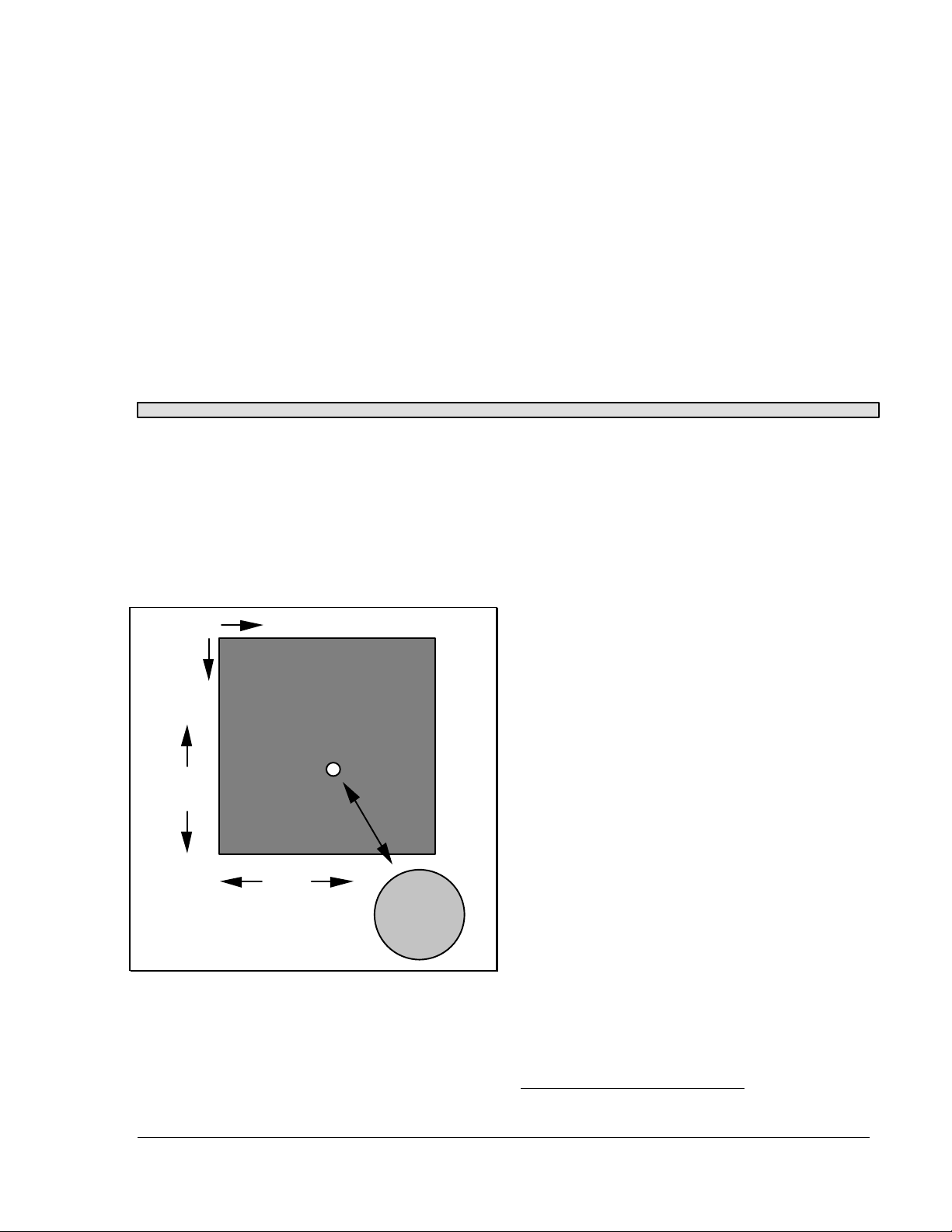
The Model ST-4 uses a charge coupled device
(CCD) detector to detect star images. The
detector can be understood by examining Figure
1. An array of 192 by 165 detector elements,
called pixels, is arranged as shown in the figure.
We refer to the horizontal axis as X, and the
vertical axis as Y.
X
Y
165
Pixels
192
Pixels
Enlarged View
Showing Pixels
Figure 1 CCD Configuration
In operation the pixels convert photons into
electrons, and store them until read out by the
ST-4's microcontroller (the ST-4 has memory for
two images, one for light frames, and one for
dark frames, as explained further below). For
example, if a star's image is present at pixel
position 121,132 the computer will determine its
position by noting the increased signal from that
pixel. If the star is drifting due to guiding errors,
it will appear at a different position in the next
exposure, say at pixel position 123,132. The
computer then calculates how far the star has
drifted from the original exposure, and toggles
the telescope drive accordingly.
The microcontroller (in the ST-4) can take an
exposure (called integration), read out all the
pixel values, and calculate the necessary
telescope correction in less than a second. The
tremendous sensitivity of the CCD enables guide
stars as faint as 8th magnitude to be tracked with
a 1 second exposure and a 60 mm guide
telescope.
The calculating power of the ST-4 enables the
star's location to be determined to a fraction of a
pixel accuracy, enabling very accurate tracking.
Imaging Overview
The Microcontroller referred to in the tracking
section is built into the ST-4. This microcontroller
can communicate to an XT or AT compatible PC,
or a Macintosh* , over the ST-4's RS-232 serial
link (the serial interface of the ST-4 is also
compatible with the RS-422 ports used on the
Macintosh).
A full image can be transmitted at 19.2K
baud within 18 seconds and over a distance of
100 feet. Data transfer rates as high as 57.6K
*
Macintosh is a registered trademark of Apple
Computer, Inc.
SBIG ST-4/0490 Page 1
Page 4

SBIG SANTA BARBARA INSTRUMENT GROUP
baud are supported, and work very well over
shorter cable runs. A partial image transfer
mode is also supported which sends 1/4 as many
pixels (one value for each group of four adjacent
CCD pixels) in 5 seconds. This mode of
operation is very handy for focussing the
telescope and finding objects. Finding faint
objects is easy using this method; the outline of
the Ring Nebula is clearly seen in exposures as
short as 10 seconds with an 8" Schmidt
Cassegrain Telescope (SCT) operating at f/10.
In imaging mode, the microcontroller in the
ST-4 is told to take an exposure by the PC. It
does so, and stores the resulting data in memory
within the instrument. This data is then relayed
over the serial link to the host computer. The
data is retained in the ST-4 until the next
exposure is captured or power is turned off. The
host does all of the extensive data manipulation
required by the user, such as contrast
enhancement, and also can store data on disk for
later study. This is a very attractive feature; the
computer allows a quick look to be taken at the
image, within seconds of the event, and a more
detailed look at any later time, such as a rainy
night or during the day.
The CCD can be exposed for integration
times longer than five minutes. The pixels slowly
fill-up in the dark due to a phenomena called
dark current, and they saturate at about the five
minute point when the CCD is cooled to a
temperature near -30 °C using the single stage
thermoelectric cooler used in the ST-4. The waste
heat of the thermoelectric cooler (about two
watts) is dissipated into the air by convection
around the CCD head. The CCD has a sensitivity
comparable to ASA 20,000 film, if such a film
speed were available. The CCD has a limited
resolution due to the small number of pixels;
much greater resolution would be degraded by
the limitations of most computer graphics
screens.
Note:
With the CCD running at lower than ambient
temperatures, you will wonder why dew and
frosting aren't a problem. First of all, the
chamber containing the CCD is small, and
only a small volume of air surrounds the
CCD. The small volume minimizes the total
amount of water vapor in the air, which will
frost onto the coldest surface inside the head
(which is the bottom of the CCD). Although
frost may initially form on the top of the
CCD, in a matter of minutes it will migrate
and be trapped at the back of the CCD.
System Interfaces
The following equipment is a prerequisite to
running the ST-4 CCD Star Tracker / Imaging
Camera.
1. A Telescope with pushbutton or joystick
slow motions in at least Right Ascension
and and hopefully also Declination.
2. A guide telescope, 50mm aperture or
larger, or an off axis guider arrangement.
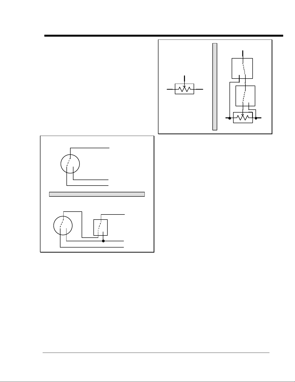
For pushbutton type controllers the ST-4 tracker
controls the telescope the same way you do;
through the RA and Declination slow-motion
adjustment switches, the interface to which is
shown in Figure 2. Four relays in the ST-4 are
used to operate the switches. Most telescope
drives have two Declination motor adjustment
switches which are normally in the 'open'
position. Pushing the button or closing the relay
both apply voltage to the motor. Study Figure 2
carefully, along with your pushbutton control, to
determine the correct configuration.
Most telescopes have one Right Ascension
switch which is normally closed; opening this
switch slows down the drive. The other Right
Ascension switch is normally open; closing this
switch speeds up the drive. It is apparent that
the relay contacts which are brought out on the
cable, 4 groups of three (normally open, normally
closed, and common) are all that is necessary to
control the telescope. The cable pinouts are
described in Appendix A.
When the ST-4 tracker is connected to the
telescope, the hand controller is not disabled, and
Page 2 SBIG ST-4/0490
Page 5
SBIG SANTA BARBARA INSTRUMENT GROUP
still operates normally. If the telescope control is
modified for the ST-4, and the ST-4 is unplugged,
the drive may not run since the normally closed
connection in the ST-4 has now been removed. If
this situation is a problem it is best to build up a
mating connector to replace the ST-4 box that has
the appropriate pins shorted together (usually
just two are required to enable the RA drive to
work).
For joystick type controllers, the four relays
in the ST-4 are used to simulate the joystick being
pushed to its limits. Two relays are used for each
axis or rheostat of the joystick as shown in Figure
3. For the Right Ascension rheostat you would
use the +X and -X relays, and for the Declination
rheostat you would use the +Y and -Y rheostat.
A: Standard Hand Controller Switch
c
switch
common
A
rheostat
B
A: Standard Joystick
Figure 3 Joystick Interface
C
A
relay
c
nc
no
relay
nccno
B C
B: Modified Joystick
nonc
B: Modified Hand Controller Switch
c
nonc
Figure 2 Pushbutton Interface
normally open
normally closed
c
relay
nonc
common
normally open
normally closed
SBIG ST-4/0489 Page 3
Page 6
SBIG SANTA BARBARA INSTRUMENT GROUP
STAR TRACKING OPERATION
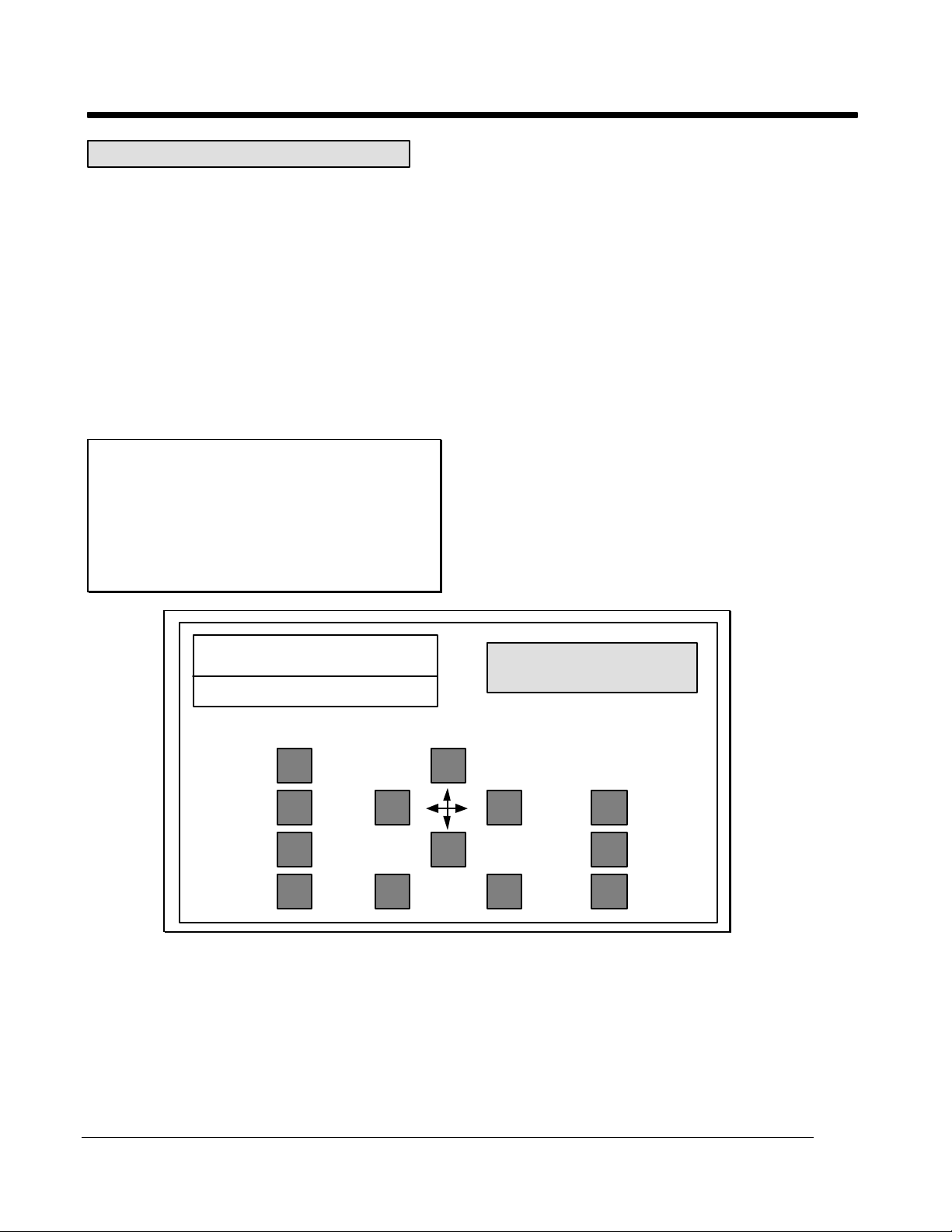
The instrument panel is illustrated in Figure 4.
The ST-4 instrument is furnished with a power
cable, a cable to the CCD, and a third cable for
the telescope's hand controller. There is no
power switch; plugging in the power turns the
instrument on. The instrument will come-up in
FIND AND FOCUS mode, which displays the
greatest pixel value found in the readout of the
CCD array, and the location of that pixel. The
greatest pixel reading will drop as the CCD cools
in temperature. After about 2 minutes, the CCD
will have cooled to its optimum temperature.
Note:
The display values range from 0 to 99
corresponding to percentage. Pixel X and Y
values of 50 correspond to a pixel centered
within the CCD, while a brightness value of
99 corresponds to a completely saturated
pixel, i.e., the star is too bright for tracking.
Instrument Startup for Tracking Purposes
1. Insert the CCD head into the eyepiece tube
such that it seats accurately against the tube.
The CCD will not be damaged by light when
powered, so it can be easily handled.
2. Begin calibrating the CCD by completely
blocking the open end of the telescope to
remove all light (the CCD is very sensitive it will saturate in very low ambient light
levels).
3. Observe the VALUE reading. This reading
should fall to a reading of around 10 and
stabilize within two minutes of the
instrument being powered-on. Press the
INTERRUPT button to halt the FIND AND
FOCUS mode (or any other mode for that
matter).
4. Push the TAKE DARK FRAME button. The
microcontroller will readout the CCD and put
the data in the dark frame memory.
ASTRONOMICAL
SBIG
STAR TRACKER/IMAGING CAMERA
TAKE
DARK
FRAME
FIND
AND
FOCUS
CALIBRATE
DRIVE
TRACK
Figure 4 Instrument Panel
5. Push the FIND AND FOCUS button and
uncover the telescope to begin the collection
of light by the ST-4. The instrument will
automatically begin taking frames of CCD
data, subtract the dark frame stored in
memory, and display the maximum value.
Direct the telescope to a star and adjust the
telescope's position to approximately center
INSTRUMENTS
MODE SELECT
89 45 37
VALUE X Y
INTERRUPT
MENU
ADJUST
the star image on the CCD by noting the
reading on the X and Y displays.
6. If the star is too bright (VALUE reading 99)
then either the exposure must be reduced, or
a fainter star chosen for tracking. In order to
correct this condition, press the INTERRUPT
button to stop the collection of data, and
Page 4 SBIG ST-4/0490
Page 7

SBIG SANTA BARBARA INSTRUMENT GROUP
return control of the ST-4 instrument to the
keyboard.
Push the MENU button. The brightness
display will then read "EA" (exposure adjust)
and a "1" will appear on the X pixel display
(indicating a default exposure time of one
second).
Repeatedly pushing the ADJUST key will
scroll through a list of exposure times, from
0.1 second, to 20 seconds. Adjusting the
exposure time to shorter times will reduce the
star brightness, while choosing a longer
exposure time will increase star brightness.
When the desired exposure time has been
chosen, press the MENU button again (the
ST-4 will display "CA" (Calibration Adjust),
and then press it several more times until you
see a bA displayed in the value box. bA
stands for brightness adjust; two modes are
available, A for average, or F for faint. F
increases sensitivity by 9 times. You should
set this parameter to A for initial
familiarization. Press the MENU button
again until you see the boost (b) parameter
displayed. This is a boost factor, where
greater values mean greater gain. Initially set
this value to 1. Press the MENU button again
to return to the normal operating mode (after
being interrupted "HELLO" appears on the
display).
Note:
You must take a new dark frame if you
change the exposure time, the brightness
adjust, or the boost factor.
Table 1. This assumes a 1 second exposure
and a typical response of the CCD. Use this
as a reference for determining whether the
system is properly focussed.
Star ST-4 VALUE Reading
Magnitude 60mm Refractor 8 inch SCT
4 99 99
5 60 99
6 24 99
7 9* 80
8 4
9 1
10 - 5
Table 1 Typical VALUE readings
8. When the focus is adjusted, remove the CCD
and insert an eyepiece into the tube, sliding
the eyepiece in the tube until the image is in
sharp visual focus. With a knife or other
sharp object, scribe the eyepiece on its side at
the end of the tube. This eyepiece can then be
used to quickly center and focus the CCD in
the future Place the CCD back into the tube
so that it seats against the tube as before.
9. Position the star image approximately in the
center of the CCD (X=50, Y=50) using the
telescope controls. Push the UP, DOWN,
LEFT, and RIGHT buttons for a few seconds
to make sure that each relay control is
correctly interfaced to the telescope handheld controller unit. If the buttons are
working correctly, the star image will move
in four different directions (but not
necessarily up, down, left, and right).
*
*
32
13
*
7. When the brightness level has been adjusted
to an acceptable level, focus the telescope by
turning the focus knob and observing the
VALUE display. At best focus, this number
is maximum. Be careful to take your hand off
the telescope between adjustments or the
telescope vibration will smear the star image
over multiple pixels within the CCD,
reducing the brightness. Atmospheric
turbulence will also tend to smear the image,
so it may be helpful to watch several
sequential exposures when critically
focussing the image.
A table of typical VALUE readings for
different magnitude stars is shown below in
SBIG ST-4/0489 Page 5
10. Push the CALIBRATE button. The ST-4 will
automatically drive the telescope in each
direction, determine which direction
corresponds to +X and +Y, and calculate the
correction speed of your drive in all four
directions (in pixels moved per second). This
process takes about 30 seconds. This is a
four-step process with the ST-4 exercising the
four relays, and after each step the ST-4 will
momentarily display the location and
brightness of the brightest object in the field
of view. If the image moves too little (less
*
Use an increased boost factor and the faint star
mode when working at these levels.
Page 8

SBIG SANTA BARBARA INSTRUMENT GROUP
than 2 units) or too far (greater than 30 units)
the relay closure time should be adjusted by
pressing the MENU key twice to get to the
"CA" option, and then repeatedly pressing
the ADJUST key to scroll through the time
adjustment values (1 to 20 seconds).
11. If no errors are displayed at the end of the
CALIBRATE procedure (E1 or E2 in the
Value display), then position the guide star
on the center of the CCD, adjust the exposure
time if necessary, and then press the TRACK
button. The ST-4 will automatically guide the
telescope until the INTERRUPT button is
pressed.
Note:
The ST-4 constantly corrects drive
adjustment times to try to improve tracking.
The visual X and Y displays show the
tracking error seen during each exposure in
units of 0.2 pixels (i.e. a displayed Y value of
-3 indicates that the star moved 0.6 pixels in
the -Y direction during the exposure). The
number displayed after the A in the value
location is the average error for the last 16
correction periods.
If the star is completely lost during an exposure,
the unit will stop tracking and the display will
display the brightness and location of the
brightest object in the field of view (like the FIND
AND FOCUS mode), and the track lost relay will
be activated for one second after 5 consecutive
misses. The telescope will not be corrected again
until the star reappears.
Calibration steps 10 and 11 should be
repeated whenever the telescope is substantially
re-positioned in Declination (to correct for longer
RA adjustments near the poles). Calibration
should also be repeated if the telescope mount is
of German Equatorial design and the telescope
tube flips from one side of the mount to the other
(reversing adjustment directions). Care should
be taken to orient the CCD head so the RA and
Declination axes line-up with the sides of the
CCD head (you can tell by looking through the
glass window at the CCD or by noting the
orientation of the Serial Number tag on the rear
of the head which is oriented like the CCD). This
adjustment is not critical. The tracker will work
in any orientation. It just makes it easier to make
sense out of the x and y readings and to use the
pushbuttons if the axes are lined up to the RA
and Declination axes.
Explanation of Menu Items
The menu choices which can be adjusted to a
particular telescope's configuration can be
viewed by pressing the MENU button
repeatedly. The different menu items have the
following effect:
Note:
For each menu item, pressing the ADJUST
button repeatedly will scroll through the
choices, finally jumping back to the lowest
value choice. There is no way to back up.
EA: Exposure Adjust
The exposure (integration time) used by the
ST-4 in the tracking mode can be set to be
from 0.1 to 20 seconds. The readout time of
the array is 0.14 seconds; the smearing
produced by the readout time for short
integration times is not significant in the
tracking mode.
CA: Calibration Adjust
The amount of time (in seconds) the drive is
left on during each move when the
CALIBRATE mode is executed. If the time is
too short the move will not be accurately
determined. If it is too long the star will
move off the array. Set this parameter such
that a move of 5 to 30 units result.
SA: Scintillation Adjust
The ST-4 modifies the correction factors
determined in the CALIBRATE mode, if
necessary, to improve the tracking. This
modification is performed only if errors
greater than the SA factor are seen (the SA
factor is in pixels). Telescopes with extremely
long focal lengths (>10 feet) may find the
tracking is improved if this value is increased.
Also, its setting should be increased if the ST4 shows any tendency to "run away" during
tracking.
Page 6 SBIG ST-4/0490
Page 9

SBIG SANTA BARBARA INSTRUMENT GROUP
bA: Brightness Adjustment
Setting this to A is the normal mode. If this
parameter is set to F the ST-4 will set each
pixel equal to the sum of the 3 x 3 pixel box
centered on that pixel prior to performing the
tracking calculation. Since star images are
often smeared over several pixels, this
collects more light from a faint star. A new
dark frame should be taken after altering this
value.
H1: Hysteresis (backlash) Adjustment, X-axis
This parameter sets the amount of extra time
that the drive is operated when the direction
of adjustment is changed. Many telescopes
have severe backlash, and the star image may
not move for several seconds after a
correction is made. The parameter is the
number of tenth second increments added to
the calculated move when the move direction
is reversed from the previous move.
H2: Hysteresis Adjustment, Y-axis
This parameter is identical to the H1
parameter above except for the Y-axis.
b: Boost factor
This parameter boosts the internal gain of the
ST-4, enabling fainter stars to be tracked with
short exposures. Care must be taken that
thermal variations of the CCD head do not
cause the star to be lost when working with
very faint stars. If this value is altered a new
dark frame must be captured.
Please review the problem section at the end of
this manual if problems are encountered during
tracking.
SBIG ST-4/0489 Page 7
Page 10

SBIG SANTA BARBARA INSTRUMENT GROUP
IMAGING CAMERA OPERATION
The ST-4 works quite well as an electronic
imaging camera when connected to either an IBM
PC or compatible or an Apple Macintosh. Some
details concerning the operation of the CCD in
this mode are necessary to understand all the
controls and features available in this mode.
CCD Pixel Dimensions
The CCD pixels are not square. Their dimensions
are 0.01375 millimeters wide in the X-direction
and 0.016 millimeters tall in the Y-direction.
Note that the CCD active area is therefore 2.64 by
2.64 millimeters, or exactly square (about one
tenth inch on a side).
Caveats of CCD Readout
The CCD is read out electronically by shifting
each row of pixels into a readout register at the
Y=0 position of the CCD, and then shifting the
row out through an amplifier at the X=0 position.
The entire array shifts down one row when a row
is shifted into the readout register, and a blank
row is inserted at the Y=165 position. Note that
the CCD elements are still collecting light as they
step down to the readout register. Most
commercial CCD cameras use a more expensive
CCD which has what is known as a frame
transfer readout mode, where all active pixels are
shifted very quickly into a pixel array screened
from the light by a metal layer, and then read out
slowly. The SBIG ST-4 CCD minimizes the effect
of not having a frame transfer buffer by reading
out the array very quickly, in about 0.14 seconds.
As long as the CCD exposure is greater than
about one second this technique will reduce
streaking of the stars to acceptable levels.
Planets pose a particular problem to the CCD
since they are so bright that exposures of 1
second at f/10 are badly overexposed. The ST-4
has a Half Frame mode for planets and bright
stars to solve this problem. In the Half Frame
mode the upper half of the CCD is used as a
frame buffer for a bright image positioned in the
lower half of the CCD. A short exposure can be
taken (down to 0.01 seconds) and the bottom
half of the array shifted rapidly up to the upper
half. The 82 lines of short exposure data can then
be readout at the normal rate. This method
works quite well, and uses enough pixels such
that 0.5 arcsecond per pixel scale factors can be
achieved while viewing an entire planet.
Unfortunately, this technique does not work
for the moon, since the moon's image typically
fills the CCD. The only way to image the moon is
to use neutral density filters to attenuate the light
down to where the CCD can be used for a 1
second exposure without saturating. The same
holds true for images of terrestrial scenes during
daylight.
When a long exposure is taken, a glow will be
noticed in the upper left corner of the image, near
pixel (1,1). This is apparently due to heating of
the array by the readout electronics increasing
the dark current. This glow can saturate the
array in the corner in exposures several minutes
long and cause a blank region to appear in the
subtracted data. Using exposures short enough
that saturation does not occur in the corner will
reduce this cosmetic problem to acceptable levels.
Dark Current
The CCD can not take an unlimited exposure.
During an exposure in the dark the pixels will
slowly fill up due to an effect known as the dark
current of the device. This dark current is
reduced by cooling, and this is why the CCD is
mounted on a single stage thermoelectric cooler
in the CCD head. The window is used over the
CCD to keep moisture from the CCD while it is
powered. If the window is removed the CCD
will frost rapidly (in seconds). In a room
temperature environment the cooled CCD pixels
take about 5 minutes to fill up due to dark
current. At lower ambient temperatures the CCD
will take longer (maximum exposure time
doubles for roughly every 20 °F drop in
temperature) until around 32 °F, where the cooler
power is reduced to avoid damaging the CCD
with excessive cold. The dark current can be
subtracted from images as described in a later
section, but the effects of the dark current filling
the CCD can not be avoided.
CCD vs Film
The CCD is very good at the most difficult
astronomical imaging problem; imaging small,
Page 8 SBIG ST-4/0490
Page 11

SBIG SANTA BARBARA INSTRUMENT GROUP
faint objects. For such scenes long exposures are
typically required. The CCD based system has
several advantages over film; greater speed,
quantitative accuracy, ability to increase contrast
and subtract sky background with a few
keystrokes, the ability to co-add multiple images
to increase sensitivity without tedious darkroom
operations, wider spectral range, and instant
examination of the images at the telescope for
quality. Film has the advantages of a much
larger format, color, convenience, and
independence of the wall plug (the ST-4 can be
battery operated in conjunction with a laptop
computer, though). After some use you will find
that film is best for producing sensational color
pictures, and the CCD is best for planets, small
faint objects, and general scientific work such as
variable star monitoring and position
determination. It is for this reason that we
designed the ST-4 to support both efforts, as a
stand-alone tracker, or as an imaging camera.
Our reliance on serial communications slows
down the image update rate, but allows the use
of portable laptop computers which seldom will
accept a PC card.
SBIG ST-4/0489 Page 9
Page 12

SBIG SANTA BARBARA INSTRUMENT GROUP
HOST COMPUTER SOFTWARE OVERVIEW
This section describes the features of the host
software used to interface the ST-4 to either an
IBM PC or compatible or a Macintosh. You will
want to read this section independent of the type
of computer you have, and will also need to read
the section below dealing with the type of
computer you own.
Displaying Images
One of the obvious features of the software is its
ability to display the images taken with the CCD
camera. There is much latitude in the processing
of the images due to the "digital" nature of the
images and the availability of personal computers
with graphics displays.
Adjusting the Contrast
Any image taken by the ST-4 consists of an array
of 192 x 165 pixel values, with each pixel value
having 8 bits of accuracy or in other words values
from 0 (completely dark) to 255 (saturated).
Although any one pixel can have this dynamic
range, typically the interesting aspects of an
image will be constrained to a more limited
range.
There will usually be a background level
associated with the image, which is like a
spatially uniform intensity level, due to dark
current, sky background, or uniform luminosity.
In addition, the bright stars in an image may
saturate, or you may be interested in examining
low-level luminosity (such as nebulosity). For
these reasons, the image's contrast can be
enhanced with the use of two parameters:
Background (sometimes abbreviated as Back) and
Range.
The Background parameter specifies an
intensity level at which any pixel below that
intensity will appear black in the image.
Increasing the Background parameter will have
the effect of masking or hiding the uniform
background, or low-level intensities. The Range
parameter is then used to specify the range of
pixel values above the Background level that will
cause the image to saturate on the display. As an
example setting the Background parameter to 25
and the Range parameter to 50 will cause any
pixels with intensity less than 25 to be displayed
as black, any pixel values between 25 and 75
(25+50) to be displayed with a gray scale, and any
pixels above 75 to be completely white.
You will want to experiment with the settings
of the Background and Range parameters to get a
good feel for how they affect the image. These
parameters do not physically change the image
data, but only affect the way the image is
displayed. We will refer to the processing of the
data to increase the contrast as "stretching the
data".
The software can automatically pick an
appropriate set of values for the Background and
Range parameters using an Auto-Contrast
feature. It does this by noting the number of
pixels at each of the 256 possible intensity levels
(called a Histogram) and setting the Background
and Range parameters based upon that
calculation. This works quite well for images of
extended objects (nebulae, the moon, etc.). For
images of star fields you can try Auto-Contrast,
but will probably get better results by manually
adjusting the Background and Range parameters.
One other feature of the host software in the
image display mode is Presentation Mode, where
the image is centered on the screen (horizontally
and vertically) and the non-image areas of the
screen are blacked-out. This Presentation Mode
is quite handy for taking photographs of the
screen for presentations, etc.
Image Smoothing and Inversion
Another image processing technique available for
the displayed images is image smoothing.
Visually, image smoothing reduces the effects of
noise by smoothing out rapid variations in pixel
brightness. This is accomplished by making each
pixel in the displayed image be a weighted
average of its own pixel value and the values of
its eight neighbors. Finally, the displayed images
can be "Inverted", meaning black areas become
white and vice versa. Visually this is like looking
at a negative, and can produce good results with
images showing subtle nebulosity. Also, it seems
that you can push the contrast harder on Inverted
images without the saturated regions detracting
from the image appearance.
Crosshairs and Photometric Analysis
Due to the linear properties of CCDs and the
digital nature of the image data, photometric
Page 10 SBIG ST-4/0490
Page 13
SBIG SANTA BARBARA INSTRUMENT GROUP
analysis of CCD images is easily achieved when
compared to techniques used with film. This
section discusses the photometric capabilities of
the ST-4 and its host software.
Scope Factors
Several telescope and calibration factors are
required by the computer software to correctly
calculate star brightnesses and separations. The
telescope focal length in inches and aperture area
in square inches are required, as well as a
calibration factor. The focal length is usually just
the focal length of the telescope, but can be
adjusted for such things as barlows and image
processing techniques such as image zooming.
The calibration factor is the reading that would
be produced from the CCD by a zero magnitude
star focused onto one pixel by a lens with 1
square inch of area, with an integration time of 1
second (with a gain factor of 1). Its value is
typically around 12000, but will vary due to
atmospheric and telescopic transmission, and
CCD device variations. The calibration factor
should also be scaled with the gain (described in
the "Baseline and Gain Parameters" section
below), doubling it for a gain of 2x, tripling it for
a gain of 3x, etc.
Note:
Atmospheric transmission varies with the
elevation of the star, so careful work will
require attention to this detail as well as to
the stellar temperature.
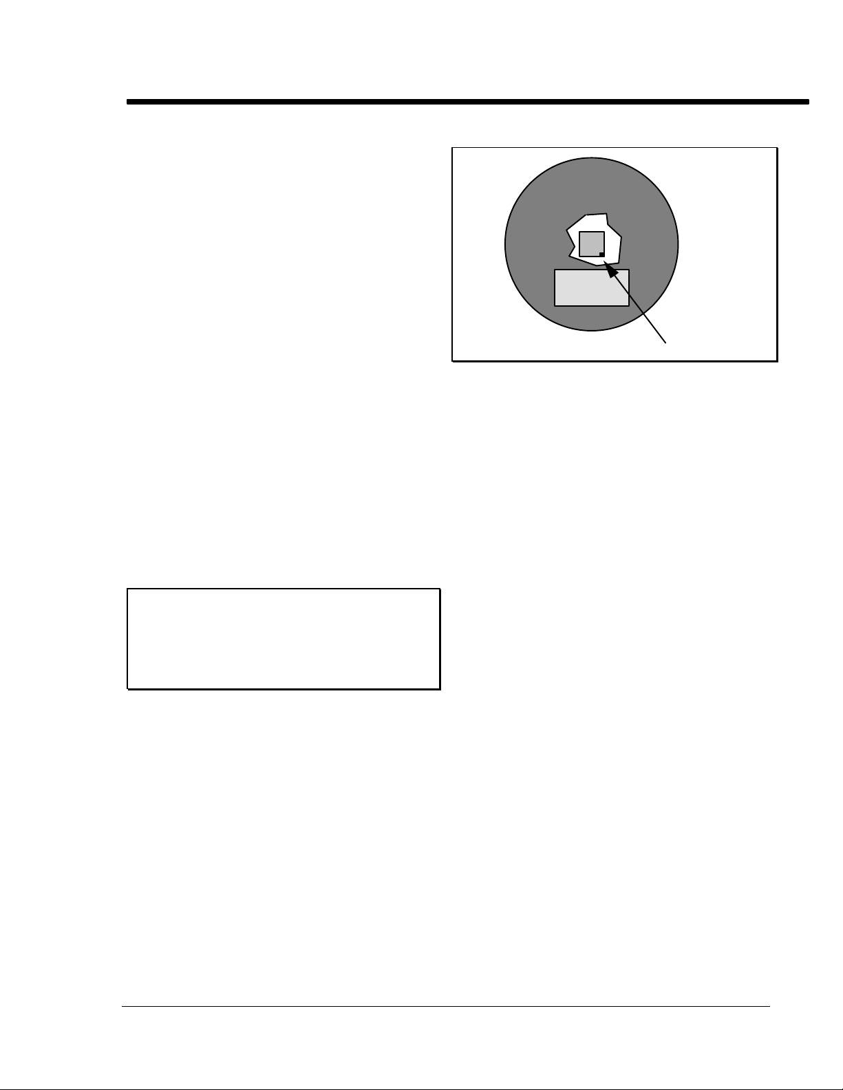
Pixel Coordinates and Intensities
The CCD is configured as illustrated before in
Figure 1. An array of light sensitive detectors,
called pixels, are arranged in an array of 192 by
165 pixels. In this manual and in all other
references we will refer to the 192 pixel wide
dimension as the X-direction and the 165 pixel
tall direction as the Y-direction (see Figure 1).
When an image is displayed on the computer
screen pixel number (1,1) refers to the pixel with
the (x,y) location corresponding to the upper left
hand corner of the screen. X increases to the
right, and Y increases toward the bottom of the
screen. The position of pixel 1,1 on the CCD can
be physically determined by referring to the
placement of the serial number tag on the rear of
the CCD head as shown below in Figure 4.
Pixel 1,1
Figure 4 Pixel 1,1 location
The host software allows a crosshair to be
moved across the image, and the coordinates of
the crosshair (in pixels) and the brightness of the
pixel under the crosshair are displayed.
Additionally, a weighted average intensity of the
pixel under the crosshair and its eight neighbors
is also shown. These values of the coordinates,
intensity, and average intensity are the simplest
form of photometry available in the host
software. They are quite handy for setting the
Background and Range parameters and for
determining the image background level (due to
sky background or dark current) and
determining the optimum exposure time.
Magnitudes and Separations
The host software can also measure stellar
magnitudes as well as diffuse magnitudes and
angular separations between objects.
The determination of stellar magnitudes
involves measuring the total light emitted by a
star, or in other words adding the intensity
contributions of all the pixels illuminated by the
star. Star images will rarely be constrained to a
single pixel, hence the requirement for
accumulating the intensity from all illuminated
pixels. In practice, a 5 x 5 box of pixels is used in
determining the magnitude although other size
boxes (3 x 3, 7 x 7, etc.) can sometimes be
specified. Since the magnitude scale is
logarithmic (an increase of 1 magnitude
corresponds to a star which is roughly 2.5 times
as faint) the calculation of stellar magnitude
involves taking the log of the accumulated pixel
intensities. Finally, to accurately measure
SBIG ST-4/0489 Page 11
Page 14

SBIG SANTA BARBARA INSTRUMENT GROUP
magnitudes the background level must be
subtracted. This is done by moving the crosshair
to a dark area of the image and specifying that
region as being typical of the background
intensity for the image. This specification of the
background allows the magnitude calculations to
be independent of effects such as dark current or
sky background. The factors that affect the
calculation of stellar magnitude are: Exposure
time, Aperture area, and Calibration factor.
The diffuse magnitude (also called surface
brightness) of diffuse objects is the magnitude per
square arc-second, and is calculated identically to
the magnitude calculation discussed above
except that the accumulated pixel intensities are
divided by the area of the 5 x 5 box in square
arc-seconds. The factors that affect the
calculation of diffuse magnitude are: Exposure
time, Aperture area, Focal length, and Calibration
Factor.
The host software also allows you to measure
the angular separation between objects in an
image. This is done by moving the crosshair to
the first object, establishing that position as a
reference position, and then moving the crosshair
to the second object. The software then displays
the angular separation and orientation (in
degrees, clockwise of vertical) of the crosshair's
position relative to the fixed reference position.
The calculation of the separation between two
objects is only dependent on the dimensions of
the CCD pixels and the focal length of the
telescope used (which must be accurately
entered). This usually requires experimental
determination using known double stars for
precision. The direction corresponding to eastwest in a setup can be determined by taking an
image of a star, letting the image drift for a few
seconds, and taking another image. The images
can then be co-added and the line between the
two images of the same star delineates the EastWest direction.
Other Image Processing Techniques
The host software uses other image processing
techniques besides contrast enhancement,
smoothing, inversion, and photometric analysis.
These other techniques are discussed in this
section.
Flipping the Image
Some inspection will reveal that the screen image
is flipped about a horizontal axis relative to the
CCD. The horizontal and vertical flip commands
enable a picture to be oriented correctly no
matter what combination of telescope and prisms
is used to form the image. Also, the flip
commands are quite useful for making an image's
orientation match that of published images.
These commands actually modify the image data,
and hence the results of using these commands
are retained if the image is saved after these
commands are applied to an image.
Zooming
The host software allows you to zoom in on an
area in the image by moving a zoom-box over the
image until the zoom-box is positioned at the
desired region where the zoom may be
completed. The zoom-box is quarter sized (48 x
41 pixels), and the pixels within it are then
zoomed to a full 192 x 165 sized image and
interpolation used to fill in the "missing pixels".
The zoomed image can then be used with all the
photometric analysis software, etc., and can also
be saved. Depending on the amount of host
memory available when the zoom is performed,
the zoom either writes over the original image
data (you are warned first) or the original data is
retained and the image can be un-zoomed later
(unless the zoomed data is saved on disk in
which case the original un-zoomed data is
discarded).
Zooming can be quite handy for examining
close binary stars, and small detail, but is no
substitute for higher magnification images since
the zooming process doesn't contain any more
information than the original 192 x 165 pixel
image contained.
Histograms
The host software can also calculate and display
an image's histogram, which is a count of the
number of pixels at each of the 256 possible (0
through 255) intensity levels. The histogram can
be useful for determining the settings of the
Background and Range contrast parameters (like
the Auto-Contrast does), for determining the
dark current or sky background level, and for
determining the optimum exposure time.
Page 12 SBIG ST-4/0490
Page 15

SBIG SANTA BARBARA INSTRUMENT GROUP
Dithering
Although the images from the CCD camera can
have 256 possible intensity levels or gray-scales,
not all computers have the ability to display such
a wide range. Some graphics displays can only
display two colors; black pixels and white pixels
(Hercules adapters and Mac Pluses for example).
Something must be done on these displays or else
images would not look good due to their ultrahigh contrast or lack of gray scale. In these cases
a technique called dithering is used to increase
the number of gray scales available.
Dithering involves using a cell of display
pixels (2 x 2, 3 x 3, etc.) for each image pixel, and
strategically turning on combinations of pixels
within that cell to simulate the gray scale. This
works well because the eye does a good job of
averaging the intensity over the entire cell. The
trade-off is that you require a larger number of
pixels for an image, or must decrease the spatial
resolution of the image to accommodate a fixed
number of pixels.
Dithering can also be used to increase the
gray-scale capabilities of displays with more than
two but a limited number of gray-scales or colors.
For example, a 2 x 2 dithering cell gives 61
different gray scales on a display adapter with
only 16 shades of gray (such as the high-res VGA
mode and some Macintosh II video cards).
Making the Camera Connection
An important aspect of the host software is its
ability to interface to and communicate with the
ST-4 over the serial port. If you have ever dealt
with serial interfaces you should be happy to
know that much effort has been given to make
the host to ST-4 interface as easy as possible
while maintaining a high degree of compatibility
and flexibility.
On power-up, the ST-4 wakes up at 9600
baud, which is quite safe in terms of being able to
establish a reliable communications link with the
camera, but which as also a bit taxing of your
patience in terms of image download times. The
host can however program the ST-4 to
communicate at any baud rate from a lowly 1200
baud to the highest rate of 57.6K baud. The
actual baud rate used will depend on how you
configure the host program and/or the
environment in which the host and ST-4 exist
(mainly the cable length between the host and the
ST-4). The host software can be configured to
talk to the ST-4 at the fixed baud rates of 1200,
9600, 19.2K, and 57.6K or can be configured for
Auto Baud mode.
In the fixed modes, the host software will
program the ST-4 to the selected baud rate and
always attempt to communicate at that rate. In
some circumstances it may be possible to pick too
high a baud rate for reliable communications, and
a lower rate may need to be selected. This is
described further below.
In the Auto Baud mode the host software will
sequentially program the ST-4 for the highest
possible baud rate (57.6K baud), and then test the
communications link, lowering the baud rate as
necessary to establish a link with the camera. The
only times this "auto baud" process will occur is
when the host software is first run or when the
Establish link command is executed under user
control. Another feature of the Auto Baud mode
is that if the host ever looses the communications
link with the ST-4, it will search around (in baud)
until it finds the camera or gives up. In this case
however, it will not try to change the ST-4's baud
rate, but will continue to communicate at the
discovered rate.
We suggest you use the Auto Baud mode,
and let the computer determine the best
communications rate. If you do, you should
always make sure the communications link is
established with the ST-4 prior to downloading
images, by either having the ST-4 connected to
the selected port and powered-up when the host
software is first run, or by explicitly establishing
the communications link using the Establish link
command. Also, if you ever turn off the ST-4 or
loose contact with it you will need to use the
Establish link command to re-program the
highest possible communications rate. If
however you always use the same configuration
(cable length, environment, etc.) then selecting
one of the fixed rates may slightly speed up the
start-up phase of the host software since it won't
have to run the "auto baud" process.
SBIG ST-4/0489 Page 13
Page 16

SBIG SANTA BARBARA INSTRUMENT GROUP
Important Note:
The ST-4 sends a check digit with each line of
data. The host software verifies the data
using this check digit. If it does not agree,
the computer requests that the line be sent
again. After four sequential failures a
communications link failure is indicated.
Under no circumstances will garbage data be
transmitted and displayed without the
operator knowing it.
Images and Image Modes
This section discusses the different types of
images you can take, and the different image
modes that the host software and ST-4 support to
make it easier to take images of the variety of
celestial objects.
Light and Dark Frames
Taking a typical long exposure requires several
steps. The simplest technique is to take a long
exposure of the object, save the image, and then
take an exposure of identical length with the
telescope blocked, and save this image also. The
image of the object will be referred to as the light
frame, and the blocked frame as the dark frame.
When the dark frame is subtracted from the
light frame (using the host software) the random
variations in the dark current from pixel to pixel
are eliminated and the picture quality improves
considerably, becoming much smoother and less
noisy. Exposures longer than 10 seconds can
generally be improved by this technique. The
only drawback with this technique is that the
range of the data is reduced. The 8 bit readout
electronics produce a value ranging from 0 to 255
for each pixel, and if the dark scene has an
average value of 191, only 64 units of range are
left in the image. This is more than adequate for
producing an attractive image, but better
performance can be achieved by boosting the
gain as discussed in the "Baseline and Gain
Parameters" section below.
Co-Adding Images
In addition to subtracting dark frames from light
frames, the host software allows you to add
images together. You will typically use this on
long exposure images to reduce the noise or
smooth the data by increasing the signal level.
As previously mentioned, you can not take
infinitely long exposures because the CCD will
eventually saturate from the effects of the dark
current. You can however add several long
exposures (after subtracting the dark frames from
each of the light frames) to make an image which,
while not exactly the same as a longer exposure,
will have the added benefits of greater signal to
noise (S/N) and show less graininess.
In practice, you will typically add three or
four images together. Adding more is not much
help because the improvement in S/N goes as the
square-root of the number of co-added images;
two co-added images increases the S/N to 141%,
three increases it to 173%, four increases it to
200%, and nine would increase it to 300%. Also
you will typically only be able to add a few
images before large areas of the image saturate
since the sum of the images is still restricted to an
8-bit number (0 through 255).
When co-adding images, you must tell the
host software how much (if any) to offset the 2nd
image by (in both X and Y) to correctly line up
with the 1st. You can determine these offset
amounts by noting the pixel position of some
star or particular feature on each of the images
you wish to co-add.
The Anti-Blooming Gate
CCDs suffer from an effect called blooming that
occurs when photons continue to strike pixels
that are saturated. The effect manifests itself as
streaking around objects which are roughly five
times as intense as a star which just saturates the
pixels (for a given exposure time). This effect
varies from device to device, and the CCD used
in the ST-4 has some special electronic circuitry to
reduce the effects of blooming. The ST-4 and the
host software allows an "Anti-Blooming Gate" to
be selectively enabled during exposures which
will inhibit blooming of objects up to 100 times
the saturating brightness level.
You will typically want to use the AntiBlooming Gate on long exposures. It bleeds off
charge from the CCD pixels, and reduces the
CCD dark current, allowing longer exposures.
Its only deleterious effect is that it tends to
slightly broaden bright objects (such as stars),
which is far more appealing than the detracting
streaks associated with bloomed objects.
Page 14 SBIG ST-4/0490
Page 17

SBIG SANTA BARBARA INSTRUMENT GROUP
The Baseline and Gain Parameters
As previously mentioned, long exposures will
reduce the dynamic range of images with the
background level due to dark current taking up a
good portion of the overall dynamic range
available. Again, this is because with the dark
current background using say 191 counts, only 64
remain for the image data itself. This can be
avoided using a technique where one first takes a
dark exposure of the intended duration, sets the
electronic readout baseline level (referred to as
the baseline in the host software) slightly lower
than the background level value in the dark
image, and then boosts the gain by 2, 3 or 4 times
to reduce the effects of digitizing the data. The
light frame and dark frame are then captured and
subtracted as before.
This technique is also useful for short
exposures of faint objects, which do not begin to
saturate the CCD (levels of 255). Set the baseline
to the dark sky level, and boost the gain by 4 if
short exposures are unavoidable due to drive
errors, etc. The noise of the CCD is greater at
higher pixel values; a boost of four is useful for
images in which the CCD pixel does not reach
one quarter of saturation, while a boost of two is
all that is useful at pixel levels near saturation.
Note:
The CCD has occasional "hot" pixels which
saturate first in a long exposure. These hot
pixels can show up in a subtracted image as a
black pixel, since the saturated value is the
same in light and dark exposures. Keeping
the maximum exposure below that required
to fill the CCD pixels 50% of the way will
effectively eliminate this problem.
Automatic Dark Frame Subtraction
As mentioned previously, the ST-4 has memory
for two image buffers, a light buffer and a dark
buffer. The host software allows you to capture a
dark frame and retain it in the ST-4, then on
subsequent light images, you can have the ST-4
subtract that dark frame from the light images
immediately after the image is readout from the
CCD and prior to it being sent to the host.
As always, you must manually cover the
telescope when you ask the host software to take
the dark frame. This is handy for searching an
area for an object of interest, but for your final
images (the ones you really want to keep) you
will want to capture and download both light
and dark frames and let the host software do the
subtraction. This is so the time difference
between the light and dark frames will be as
small as possible and hence any possible change
in the CCD's temperature and dark current will
be minimized.
Focussing and Special Imaging Modes
To facilitate focussing, imaging planets using the
half frame mode alluded to above, taking a series
of images and selecting the best, etc., the host
software supports the following image submodes in a grouping under a mode of operation
called the Focus Mode:
Full Frame Mode
In this mode the host software continually
takes full frame images, and downloads them
from the ST-4 and displays them.
Half Frame Mode
This mode allows using the upper half of the
CCD as an image buffer for bright objects as
described in the "Caveats of CCD
Readout"section before. Because only half of
the image is downloaded from the ST-4, the
data transmission time is only half as long as
in the full frame case. Finally note that the
only way you can take Half Frame mode
images is through the Focus Mode.
Quarter Frame Mode
In Quarter Frame Mode, the host software
first takes and downloads a full frame image.
The user then specifies an area of the full
image equal to a quarter frame by positioning
a square on the full frame image. The host
software then takes full frame images but
only downloads the pixels within the quarter
frame specified by the user, resulting in a
transmission time which is 1/4th as long as
for full frame images.
Low-Res Mode
This mode, also called one of four mode, is
also faster that the full frame mode at the cost
of image resolution. After each image is
taken, the ST-4 reduces the image to 1/4th the
SBIG ST-4/0489 Page 15
Page 18

SBIG SANTA BARBARA INSTRUMENT GROUP
number of pixels be replacing each group of 2
x 2 pixels by the average of the group. The
host software then downloads that 1/4 sized
image, which only takes 1/4th the
transmission time of a full frame image. Prior
to displaying the image, the host software
expands the image up to its full size by
interpolating between pixels. The resulting
image has 192 x 165 pixels but has lower
resolution than a full frame image due to the
image reduction and expansion. This mode is
very handy for finding faint objects since the
entire field is transmitted and the update time
is fast.
Spot Frame Mode
In this mode, after each image is taken, the
ST-4 searches through the image and locates
the brightest pixel. It then reports that value
to the host, which in turn downloads a small
subset of the image pixels surrounding the
bright spot (33 x 27 pixels). The greatly
reduced number of pixels drastically reduces
the data transmission time which is quite
handy for focussing on stars.
Track Frame Mode
Like Quarter Frame Mode, in Track Frame
Mode the host software first takes and
downloads a full frame image. The user then
specifies an 33 x 27 pixel area of the full
image by positioning a square on the full
frame image. The host software then takes
full frame images but only downloads the
pixels within the 33 x 27 pixel area specified
by the user, resulting in a short transmission
time and hence a rapid frame update rate.
The image is displayed with a cross hair
drawn through the center, and while the
screen is in the continuous update mode you
(through the host software) can move the
telescope (if the relays in the ST-4 are hooked
up) or the telescope can be moved manually.
The telescope can be guided on a faint star by
viewing the screen and making corrections,
which is much less fatiguing than guiding
through an eyepiece in an awkward position.
This mode can be used to guide on stars too
faint for the ST-4 to lock on, since the eyebrain combination is better at recognizing a
faint stellar image in the presence of grainy
readout noise.
In all the Focus sub-modes described above, the
host software displays the coordinates and
intensity of the brightest pixel in the CCD.
Additionally the host software can be configured
to pause between images, until the user gives the
go-ahead, and the host software can be
configured to use the Auto-Contrast feature
when displaying the data or can use Background
and Range values set by the user. Although the
host software has commands for simply taking an
exposure and downloading the image you will
find yourself using the Focus mode the majority
of the time. Table 2 below shows typical pixel
values you should see for various magnitude
stars for a well focussed image. These assume a 1
second exposure and typical value of 10000 for
the CCD calibration factor.
Star Star Intensities
Magnitude 60mm Refractor 8 inch SCT
4 255 255
5 150 255
6 60 255
7 24 208
8 10 83
9 4 33
10 1 13
Table 2 Typical Star Intensities
Capturing and Viewing an Image
Capturing and viewing an image at the telescope
usually requires the following procedure:
1) Find a bright star.
2) Focus the star.
3) Center the telescope on the desired object.
4) Grab an exposure of the object.
5) Grab a dark exposure if desired.
6) Subtract the dark exposure from the light.
7) Display the image and optimize the
contrast.
Start by inserting the CCD camera head into the
eyepiece tube of the telescope and entering the
Focus Mode. Configure the Focus Mode for an
exposure time of 1 second, full frame, automatic
update, no auto-contrast, and set the Background
to 0 and the Range to 255.
Page 16 SBIG ST-4/0490
Page 19

SBIG SANTA BARBARA INSTRUMENT GROUP
The computer will begin displaying the field,
updating the screen about every 10 seconds.
Position a bright star (magnitude 3 to 5) in the
center of the field and focus the image to achieve
the smallest spot. It is usually best to maximize
the peak value of the star image, which is
displayed in this mode, rather than rely on the
size of the spot to define the best focus.
Some difficulty may be encountered in
finding the star in the field of view. Use an
eyepiece in the tube to center the star before
inserting the CCD head. The CCD is quite small,
so try to position the star within the center 10% of
the field of view of a low power eyepiece. When
the star has been found, centered, and focused
take the time to accurately center the star in the
guide scope to make finding objects easier in the
future. Also, remove the CCD head, insert an
eyepiece in the tube, and focus the eyepiece by
sliding it within the tube. When best visual focus
is found scribe the side of the eyepiece so the
telescope can be quickly set close to the optimum
focus the next time. Replace the CCD head,
taking care to always seat it securely against the
tube.
Now that you have found an object, exit the
Focus Mode, and vary the Background and Range
parameters to modify the display. Small values
of Range have the effect of increasing the contrast.
Stars get fatter due to the fact that the stray light
near the main image is being seen, but nebular
detail becomes more visible. The Background
should typically be set to correspond to the levels
of the black regions in the image (these levels can
be determined using the crosshairs).
Try out the different frame modes. Position
the star in the bottom half of the display screen
and then try the Half Frame mode. You will note
that the star image appears in the upper portion
of the screen. Move the star off the screen to the
top by moving the telescope and you will note
that the star reappears, but badly smeared (for a
bright star). This is important. If, in the Half
Frame mode, you have a badly smeared image it
means that you need to move the star or planet
down in the field to correctly position it for
optimum imaging. Finally try out the Quarter
Frame and Low-Res modes, and try out the two
33 x 27 pixel modes.
SBIG ST-4/0489 Page 17
Page 20

SBIG SANTA BARBARA INSTRUMENT GROUP
USING THE ST-4 WITH AN IBM PC OR
COMPATIBLE
This section describes the PC host software for
using the ST-4 as an imaging camera. You will
want to read it if you plan on connecting the ST-4
to an IBM PC or compatible computer. Also,
prior to reading this section you should read the
"Host Computer Software" section above.
Making the Camera Connection
The ST-4 is connected to the computer using the
serial cable provided with the unit. The cable
should be connected between the ST-4 and the
computer serial port, either COM 1 or 2. RS-232
serial connectors on PCs and compatibles
generally come in 2 varieties, with either a 25 or 9
pin connector. Hopefully you specified the type
you require when you placed your order and you
have the necessary adapters in the box. If you
did not, please contact SBIG or go to your local
Radio Shack, and obtain the necessary adapters.
Note:
The PC version of the ST4 program
(CCD.EXE) requires several other files found
on the floppy disk to run. The CGA.BGI,
EGA.BGI, etc. files are graphics drivers for
the various types of graphics cards supported
by the program, and the CCD.CFG file
retains the settings of key parameters
(exposure time, etc.). If you wish make an
additional running copy of the program (say
to run on your portable computer, etc.) make
sure you copy these files in addition to the
CCD.EXE file.
After you have made a backup copy of the
program and stored the original away you may
run the program by doing the following:
If you do not have a hard disk:
Insert the program disk into the disk drive, and
get into the drive directory by typing:
Note:
As the software comes on the distribution
disk it is configured for using COM 1. If
COM 1 is available you should initially use
that port. Otherwise you can use the COM 2
port but the software will have to be
configured for it (described later but for now
don't worry about it). Also the software
remembers the port for which it has been
configured and will only have to be changed
if you switch COM ports.
Running the Program
Before running the ST4 program, please make a
backup copy of it following the procedures
described in the DOS manual, and save the
original in a safe place. After successfully
connecting the ST-4 to your computer, power up
the ST-4 and computer, and run the program.
A: (and then hit enter)
You can then run the program by typing:
CCD (and then hit enter)
If you have a hard disk:
You can transfer the program and configuration
files to your hard disk using the DOS copy
command as described in your DOS manual.
After copying the files to your hard disk you
can run the program by first getting into the
directory that contains the CCD.EXE file, and
then typing:
CCD (and then hit enter)
Once you are in the program, the program
automatically initializes the serial port, and
searches for the ST-4. Since the software has been
configured (by the factory) for the Auto-Baud
mode, if it finds an ST-4 it increases the baud rate
up to the maximum the hardware will accept. A
screen message will then inform you that
communication has been established and show
the baud rate.
Page 18 SBIG ST-4/0490
Page 21

SBIG SANTA BARBARA INSTRUMENT GROUP
If you get a communication failure message,
recheck your cables, make sure the ST-4 is
powered on (red numbers should appear on the
display). Ignore any problems until you have
read the section below describing the PC
command. Then check the configuration of the
COM port and use the Establish link command.
Elements of the User Interface
This section describes the user interface of the
CCD program. We hope you will find the user
interface to be both friendly and efficient.
When you first enter the CCD program you
are put into the Command Mode. The top line of
the screen displays the main menu of commands
and is referred to as the menu bar. A command
can be selected by moving the highlighted menu
cursor to the command name using the left and
right arrow keys. The selected command may
then be invoked by pressing the Enter key. An
alternative to using the arrow keys to select the
command and pressing the Enter key (to invoke
the command) is to simply press the first letter of
the desired command. To help you remember
this, the first letter of each of the commands has
been highlighted for you.
Below the menu bar towards the bottom of
the screen are two boxed in areas called the
Status box and the Data Buffer information box.
The Status box is used by the CCD program to
communicate passive information to the user
such as the introductory message presented
when the program is first run. The Data Buffer
information box indicates whether any image
data is currently held in memory, whether that
data has been saved on disk or not, and whether
the image has been zoomed (and thus could be
un-zoomed).
The blank area between the Status box and
the menu bar is used for interacting with the
commands from the menu bar through pop-up
command screens and for important messages
from the CCD program which are also shown in
pop-up message boxes.
Become familiar with the screen by looking at
each of the commands shown on the menu bar,
and by invoking the commands to examine their
associated command screens. You can exit from
a command screen and return to the menu bar by
pressing the ESC key. If you hit the ENTER key
within any of the command screens, that
command will immediately execute.
Each command screen consists of several
parameters which can be changed by moving to
the desired line and changing the setting. You
move the flashing cursor up and down through
the command screen parameters using the
UP ARROW and DOWN ARROW keys or using
the TAB and SHIFT-TAB key combinations. Also
note that the descriptive text to the left of each
parameter contains a single highlighted character.
The highlighted character indicates that you can
move directly to that parameter by pressing the
ALT key in conjunction with the highlighted
character.
The method used to change a parameter's
setting depends on the type of parameter, of
which there are two: Ones where you select a
single choice from a list of choices and ones
where you type in some number or text. To
select a specific setting use the LEFT and RIGHT
arrow keys to highlight your choice. To change
the setting of an entry type item you type in the
value or text. You can use the BACKSPACE key
to edit a value, or the DEL key to completely
erase all the text entered in the parameter.
The Grab, Focus, Display, and Image I/O
commands are routinely used in acquiring and
viewing images, while the Camera/Scope and PC
commands are used to control the computer and
ST-4 configuration. Please keep in mind when
using the command screens that the cursor keys
or the TAB key are used to move around within
the screen. Hitting the ENTER key will cause the
command to immediately execute, and the ESC
key will get you out of the screen and abort most
commands.
Image Processing and Analysis
This section describes the commands used for
image processing and analysis; the Image I/O,
and the Display commands as well as some
portions of the PC command.
The Image I/O Command
As its name implies, the Image I/O command is
used for storing and retrieving images to and
from disk, and is also used for co-adding images,
subtracting dark frames, and editing the
telescope factors and calibration value used when
SBIG ST-4/0489 Page 19
Page 22

SBIG SANTA BARBARA INSTRUMENT GROUP
capturing an image and saved with the image on
disk.
The path parameter tells the computer which
directory to look in for files used in the Image I/O
command. The path should be blank (or set to
".\") to load and save files to the default directory
(the one you were in when you ran the CCD
program). Typically you will have a computer
with a hard disk, or one with just floppy drives,
and should follow the directions in the next two
paragraphs:
If you have a hard disk
You will probably have the CCD program in
a directory called CCD. You could save your
files in another directory called DATA (that
you had previously created) by using a path
definition of C:\DATA\. You could save the
files to a floppy disk drive by using a path of
A:. Floppy disk drive operations are slower
than hard disks, so it is best to save to the
hard disk, and later save the valuable files to
a removable floppy.
Status box will show an annotation attached to
the image, and the values of the telescope
parameters associated with the image, and the
Data Buffer information box will be updated to
reflect that fact that an image has been loaded.
After loading an image you would typically use
the Display command to display it.
Note:
The directory command screen shows a
maximum of 40 files. The files are sorted into
alphabetical order, and you can move the
cursor by hitting the starting letter of a file
name. For example, hitting the "T" key
positions the highlighting cursor on the first
file name starting with "T". This same
directory command screen is used when ever
the CCD software asks you to pick a file from
the disk. Since you will not be able to access
any files beyond 40 in each directory, you
should try to keep you images arranged with
a maximum of 40 per directory.
If you do not have a hard disk
First load the CCD program into memory
from the A: drive, then remove the CCD
source disk and insert a formatted blank disk
for data storage. Use a path of A: or B:,
whichever is appropriate. If you have two
disk drives you can keep the source disk in A:
and store the data in B:. Remember to
reinsert the source disk into the A: drive
before exiting the program (if you only have
one drive) so that the configuration data can
be saved upon exiting.
You can also set a filter in the Image I/O
command. A filter tells the computer to only
look for files with a certain name or extension. A
filter entry might be *.PIC or *.ST4, where the
asterisk is a wild card character. You can any
any filter that is valid for MS-DOS, just like with
most of the MS-DOS commands like copy, erase,
etc.
To load a file with the Image I/O command,
use the cursor to highlight the Load operation,
and hit ENTER. You will be presented with
another command screen showing the files in the
specified path matching the filter parameter.
Select the desired file using the cursor keys, and
hit ENTER again. The file will be loaded, the
To save a file that has been downloaded from the
camera or has been changed, select the Save
operation and hit ENTER. You will be asked for
the name of the file, and the file will be saved in
the directory specified by the Path parameter. If
you pick the name of an existing file, the software
will ask you if you wish to overwrite the file
before it actually performs the Save operation.
The Add image operation can be used to
co-add an image on disk to the one in memory.
Upon invoking this operation you will be
presented with the same command screen used
in the Load operation where you can select the
file you wish to add. After selecting a file you
will be presented with a third command screen
where you can specify an X and Y offset. The X
and Y offsets are the offsets of the image to be
added from the one in memory.
The Dark subtract operation can be used to
subtract a dark frame stored on disk from the
light frame currently in memory. A value of four
is added to the light image before the subtraction
is performed to insure that clipping of the image
does not occur due to slight offsets between the
two exposures.
Selecting the Edit parameters operation
allows you to change the file annotation, and edit
Page 20 SBIG ST-4/0490
Page 23

SBIG SANTA BARBARA INSTRUMENT GROUP
the telescope factors (aperture area, focal length,
and calibration factor) saved with the image.
Note:
Magnitude corrections made in the crosshair
mode described below modify the calibration
factor automatically.
The Display Command
The Display mode (accessed through the Display
command) is used to examine the image stored in
the computer's memory by a previous Focus,
Grab, or Image I/O operation. Each of the
parameters in the Display command screen and
their effects are discussed below:
Format
This item allows you to select whether the
image itself is displayed (Image option) or
whether the image's Histogram is displayed
(Histogram option).
If selected, the Histogram is shown in a
tabular format, with the Average intensity
level and the 1% intensity levels shown. The
Average intensity can be helpful in setting the
Background parameter for adjusting the image
contrast. The 1% Level can be used to
determine the proper setting of the Baseline
level to increase the dynamic range of long
exposures as discussed in the The "Baseline
and Gain Parameters" section above. Finally,
if the Histogram is selected in the Display
command screen, the settings of the other
parameters have no effect, and needn't be
changed.
If the Image option is selected, then the
image is displayed using the graphics
capability of your display adapter. In the
Image mode, the other parameters in the
Display command screen affect the image
display as described individually below.
Also note that some settings in the PC command will affect the image display, which
will be discused later.
Auto contrast
Setting this item to Yes enables the AutoContrast mode where the computer sets the
Background and Range parameters based upon
the image's histogram. If you do want Auto-
Contrast, don't change the setting of the
Background and Range parameters below or
the software will automatically deselect AutoContrast before displaying the image. This
feature allows you to specify manual contrast
mode by merely changing the setting of the
Background or Range parameters and not
worrying about whether you forgot to turn
Auto-Contrast off.
Background
This is the Background parameter which
determines the "black level" of the image.
Range
This is the Range parameter which controls
the contrast of the image.
Smoothing
Setting this item to Yes causes the image to be
smoothed prior to display, a feature which
reduces the graininess of faint nebula, and
brings out very faint stars. The smoothing
process slows down the display process
slightly and blurs the image slightly, so it is
not desirable when close double stars are
being examined, for example.
Negative image
Setting this item to Yes causes the image to be
displayed as black on a white background,
similar to a photographic negative. This can
also be used on LCD type displays popular
on portable computers to make the image
appear as a positive, negating the effects of
the LCD display's inherently "negative"
graphics display (pixels turned on are black
on an LCD vs white on a CRT).
Display mode
When this parameter is set to Analysis the
image is displayed with its annotation, and
several other pieces of textual information,
including a Display Mode menu. In this
mode you have full access to the crosshair
routines, image zooming, etc., as discussed in
detail below.
When this parameter is set to Photo the
special Presentation Mode is activated, and
you can not access the crosshairs, etc. In
Presentation mode, the horizontal axis of the
image is expanded or compressed by the
SBIG ST-4/0489 Page 21
Page 24

SBIG SANTA BARBARA INSTRUMENT GROUP
amount specified in the Aspect ratio item in
the PC command. Once entered, Presentation
Mode is exited by hitting any key.
Color select (VGA systems only)
In color mode, images are displayed with 60
hues using a color table which is like color
temperature, using blues for dark colors,
progressing through reds and yellows up to
white. In monochrome mode (this item set to
Grey scale), images are displayed with 60
shades of grey. This works correctly even on
a color monitor.
Display Analysis Mode
In Display Analysis Mode, the image is shown to
the right of the screen with the image annotation
displayed above the image, a Display Menu
below the image, and a block of text to the left of
the image showing the settings of the Background
and Range contrast parameters and whether the
image has been smoothed or zoomed.
The Display Menu has four commands
described individually below. Each of the
commands can be accessed by pressing the first
letter of the command which has been capitalized
to help you remember.
been previously zoomed and was not saved
on the disk, executing the Zoom command
restores the image to its un-zoomed state.
Otherwise executing this command enters
Zoom Mode where a portion of the image can
be enlarged to the full size of the image, and
is described in more detail below.
Esc
Hitting the ESC key while in Display Mode
returns you to the Command Mode and redraws the menu bar, Status box, etc.
Crosshair Mode
When Crosshair Mode is entered, the Display
Menu below the image is replaced with the
Crosshair Menu, the block of text in the upper
left corner of the screen is replaced by 8 lines of
Crosshair Parameters, and a '+' shaped Crosshair
is shown superimposed over the image.
The Crosshair Parameters are updated as the
Crosshair is moved around the image and are
described individually below. You should refer
to the "Crosshairs and Photometric Analysis"
section of the host software description above for
a description of the the Magnitude and Diffuse
Magnitude calculations:
X-Hairs
Executing this command enters Crosshair
Mode used for examining pixel brightnesses
and magnitudes. The Crosshair Mode is
described fully below.
Horiz flip
Executing this command causes the image to
be flipped about a horizontal axis, and
redisplayed with that new orientation. This
command actually flips the image data, and
the effect will be remembered if the image is
saved after this command is executed.
Vert flip
This command is identical to the Horiz flip
command above except that the image is
flipped about a vertical axis.
Zoom
Executing this command does one of two
things, depending on whether the image had
been previously zoomed or not (shown in the
upper left of the screen). If the image had
Pixel
These are the X and Y coordinates of the
Crosshair. Location 1,1 is in the upper left
corner of the image.
Value
This is the intensity of the pixel directly under
the Crosshair as recorded by the ST-4, and is
a number from 0 to 255.
Sm-Value
This is the average value of the pixel directly
under the Crosshair and all the pixels inside a
box centered under the Crosshair. The size of
the box can be changed and is shown in the
Boxsize parameter.
Mag
This the magnitude of the star underneath the
Crosshair. This value is calculated from the
pixel values within the box, and telescope
and calibration data stored with the image.
In most cases an accurate calculation of
magnitude requires the sky background to be
Page 22 SBIG ST-4/0490
Page 25

SBIG SANTA BARBARA INSTRUMENT GROUP
subtracted. The Crosshairs should be moved
to a dark region of the image, and the B key
hit (executing the Background command) to
take a background reading. The Mag
parameter then displays a 99. The Crosshair
should then be moved to the desired star; the
background will be automatically subtracted
and the correct magnitude displayed.
Difmag
This is the diffuse magnitude, and is used to
measure the brightness of diffuse objects such
as nebulae or galaxies in units of magnitude
per square arcsecond. Using a large box size
improves the accuracy of this reading
(provided the box is smaller than the object),
enabling extremely low surface brightness
objects to be measured.
Sep and Angle
These are the separation (in arc-seconds) and
the angle (in degrees, clockwise of vertical)
between the current position of the Crosshair
and the reference position fixed using the
Centroid or Star commands in the Crosshair
Menu.
The crosshairs can be moved using the cursor
keys, or moved faster using the 2, 4, 6, and 8 keys
on the numeric keypad (if you have one). The I,
J, K, and M keys are also treated as a "pseudokeypad", and will move the Crosshair in addition
to the SHIFTed versions of those keys. All in all,
we find it easiest to keep one hand on the SHIFT
key and use the other to work the cursor keys.
Each of the commands in the Crosshair Menu
and their effects are discussed below. Each
command can be executed by pressing the key
corresponding to the first letter or character in
that command.
Star
Executing this command fixes the reference
position for the Separation and Angle
measurements at the current position of the
Crosshair.
Centroid
This command is like the Star command
above, but higher accuracy positioning of the
reference is achieved for stellar objects by
determining the center to subpixel accuracy.
Background
This command records the background level
used in the magnitude calculations to the
average value of the pixels inside the box
centered under the current position of the
Crosshair.
Toggle box size
Executing this command toggles the boxsize
used in the average pixel, magnitude, and
diffuse magnitude calculations through the
possible values of 3 x 3 through 11 x 11. The
program goes back to the image point where
a background measurement was last made
and makes another reading at the new box
size when this command is executed.
+Mag, -Mag
These commands modify the image's
calibration factor so that the calculated
magnitude can be corrected as required for
stars of known magnitude. The SHIFT + and
SHIFT - keys change the magnitude by 0.01
magnitude, while the unshifted keys (= and -)
change it by 0.1 magnitude. The keys on the
numeric keypad work differently. The
calibration factor can be expected to vary
slightly with the transparency of the night, or
the elevation angle of the stars. Atmospheric
absorption is a significant factor when
accurate measurements are desired
Esc
When the ESC key is pressed in Crosshair
Mode the program exits that mode and
returns to Display Mode.
Zoom Mode
When Zoom Mode is entered, a zoom-box is
drawn superimposed on the image and the
Display Menu is replaced with the Zoom Menu.
The zoom-box can be moved around on the
image using the same keys used to move the
Crosshair (cursor keys and 2, 4, 6, and 8). When
the zoom-box is positioned appropriately,
pressing the ENTER key causes the image data
within the zoom-box to be expanded to the size
of a full image. The newly zoomed image is
displayed, and Display Mode is entered.
Pressing the ESC key while in Zoom Mode
SBIG ST-4/0489 Page 23
Page 26

SBIG SANTA BARBARA INSTRUMENT GROUP
merely cancels that mode and returns to Display
Mode without performing the zoom.
Zooming actually replaces the image data in
memory with the zoomed image. If the CCD
program has enough memory, the un-zoomed
image is retained, and the image can be unzoomed later by invoking the Zoom command a
second time (unless the zoomed image is saved to
disk in which case the un-zoomed image is
discarded). If there isn't enough memory, you
will have been warned when the CCD program
was first started.
Fine Tuning - The PC Command
The PC command contains items for configuring
the serial port used in communicating with the
ST-4 and for fine tuning the graphics software
used for displaying images. The items in the PC
command are discussed individually below:
Serial port
This item allows you to select which serial
port is used to communicate with the ST-4.
Baud rate
This item allows you to select the baud rate
used in communicating with the ST-4. Please
refer to the "Making the Camera Connection"
section above for a detailed discussion of how
the host software uses the setting of this item
in communicating with the ST-4.
Graphics card
You can usually leave this item set to Auto
and the CCD software will automatically
determine the graphics capability of your PC
and use the best graphics mode for
displaying images. Some combinations of
PCs and graphics adapters aren't fully
compatible with this auto-detection software,
and in those cases you can set this item to to
type of graphics adapter you have. Strange
and unusual results can occur if you specify a
graphics card type that you don't have.
Note:
Some graphics adapters will support multiple
modes such as VGA adapters that will also
do CGA and EGA emulation. These adapters
can be used in any of their supported modes.
Also, each supported graphics adapter
requires a BGI file in the same directory as
the CCD program. For example CGA mode
requires the CGA.BGI file. All the necessary
BGI files are contained on your master CCD
program disk.
Color display
In general you will set this item to Yes if you
have a color display or monitor attached to
your graphics adapter. The setting of this
item affects whether the Command Mode
screens are in color or not, and affects the
Display Mode as shown below for the various
types of graphics adapter:
EGA
In color mode (this item set to Yes),
images ares displayed with 32 hues using
blues for dark colors, progressing
through light blues and greens up to
white. In monochrome mode (this item
set to No), 60 shades of gray are used.
Due to the way EGA cards display colors,
monochrome mode will only work
correctly with a monochrome monitor.
CGA
Images displayed on CGA monitors are
displayed using 4 colors. In monochrome
mode (this item set to No), the order of
the colors are rearranged to correspond
to gray scale when used with a
monochrome monitor.
Hercules
When used with Hercules adapters the
setting of this item has no affect on the
displayed image.
Aspect ratio
This item is used in the Presentation Mode of
the Display command, and specifies how
much the horizontal axis of the image should
be shrunk (values < 1) or expanded (values >
Page 24 SBIG ST-4/0490
Page 27

SBIG SANTA BARBARA INSTRUMENT GROUP
1) to produce a square image on the monitor.
The required settings will vary depending on
the type of graphics adapter and monitor you
have.
Taking Images
This section describes the commands used for
taking and downloading images from the ST-4,
i.e. the Camera/Scope, Grab, and Focus
commands.
The Camera/Scope Command
The Camera/Scope command screen allows the
user to setup the ST-4 and computer for optimum
performance in taking images, and for indicating
the telescope parameters. The items in this
command screen affect images taken with both
the Grab and Focus commands, and are
described individually below:
Camera Setup Parameters
Gain expansion
Set this item to the desired gain as described
in the "Baseline and Gain Parameters" section
before.
Telescope Setup Parameters
Focal length
Enter in this item the focal length (in inches)
of the telescope you are using. When images
are downloaded from the ST-4 the settings of
this item and the two shown below are
copied to the image.
Aperture
Enter in this item the aperture area (in square
inches) of the telescope you are using.
Response factor
Enter in this item the desired setting of the
calibration factor for the CCD. A typical
value is 12,000.
Establish link
Setting this item to Yes and executing this
command causes the CCD program to try to
establish the communications link with the
ST-4 as described in the "Making the Camera
Connection" section before.
Anti-Blooming gate
This item allows enabling or disabling the
Anti-Blooming gate during exposures as
described in "The Anti-Blooming Gate"
section before.
Dark subtract
This item enables or disables the ST-4's dark
frame subtraction at the end of exposures as
described in the "Automatic Dark Frame
Subtraction" section before. Enabling this
item does not cause the camera to
automatically capture the dark frame. That
must be done manually using the Grab
command.
Camera baseline level
Set this item to the desired baseline level as
described in the "Baseline and Gain
Parameters" section before.
Note
Enter in this item any desired annotation for
the image. The note can be up to 78
characters long, but note that images
displayed on CGA monitors will only show
the first 40 characters.
The Grab Command
The Grab command allows taking a single
exposure, downloading, and displaying that
image and is most convenient for long exposures.
The exposure is taken after the command is
executed (you hit ENTER), and pop-up message
boxes indicate the progress of the exposure and
image downloading. The parameters in the Grab
command screen are discussed individually
below:
Exposure time
This is the exposure time, and allowed
settings range from 0.01 seconds through 10
minutes. The value is always entered in
seconds.
Take dark frame
Setting this item to Yes causes the CCD
software to have the ST-4 take an exposure
and store it in the ST-4's internal dark frame
SBIG ST-4/0489 Page 25
Page 28

SBIG SANTA BARBARA INSTRUMENT GROUP
memory (The image is not downloaded).
This dark frame can then be subtracted from
future images if the Dark subtract item in the
Camera/Scope command is enabled.
Auto display
Setting this item to Yes will cause the image to
be displayed after it is downloaded from the
ST-4.
Auto contrast
Setting this item to Yes enables the Auto-
Contrast feature if the image is automatically
displayed after downloading.
Background and Range
These items are the Background and Range
parameters used in displaying the image if it
is automatically displayed after downloading
but the Auto-Contrast feature is not enabled.
Exposure delay
Setting this to any non-zero value causes a
delay to occur after the Grab command is
executed and prior to the exposure taking
place. The software will beep every second
until the last three seconds where it will beep
every half second.
Skip exposure
Setting this item to Yes causes the software to
not take a new exposure, but download the
image in the ST-4's memory (from the
previous exposure).
The Focus Command
The Focus command allows taking a series of
exposures. It is the recommended mode to use
when taking short exposures of planets or double
stars, since many frames of data can be examined
and the best one, least corrupted by atmospheric
seeing, saved to disk. The parameters in the
Focus command screen are discussed
individually below:
Exposure time
This is the exposure time, and can range from
0.01 seconds to 10 minutes. The value is
always entered in seconds.
Auto contrast
Setting this item to Yes enables the Auto-
Contrast feature when displaying the images
downloaded from the ST-4.
Background and Range
These items are the Background and Range
parameters used in displaying the images
after downloading when the Auto-Contrast
feature is not enabled.
Frame size
Set this item to the desired frame mode as
discussed in detail in the "Focussing and
Special Imaging Modes" section before.
Note:
The CCD software will only let you save
images captured in the Full Frame, Half
Frame, or 1 of 4 (Low-Res) Frame modes.
Update mode
Setting this item to Manual causes the CCD
software to pause until the SPACE bar is hit
after each image has been downloaded and
displayed. This is quite handy when you are
trying to select one good image from a series
of images, waiting for a stable atmosphere,
etc. The CCD software will only let you save
a complete image, not one that was paused in
mid-frame. Since in some frame modes it is
difficult to exit the Focus Mode at just the
correct time, using the Manual option
alleviates this problem. Setting this item to
Automatic enables Auto-Update mode where
the software does not pause unless instructed
to by the user.
After all the parameters have been set as desired
and the ENTER key has been hit the CCD
software goes into Focus Mode.
The Focus Mode screen looks similar to the
Display Mode screen and shows a block of text in
the upper left corner, a menu at the bottom, and
as images are downloaded they are shown on the
right edge of the screen, with a white box
encompassing the image.
The block of text includes items displaying
the frame mode, whether the Automatic update
is enabled, the settings of the Background and
Range parameters, and the value and X and Y
coordinates of the brightest pixel (Peak) from the
CCD. The Peak parameters are updated after
Page 26 SBIG ST-4/0490
Page 29

SBIG SANTA BARBARA INSTRUMENT GROUP
each exposure, before the image is downloaded
and displayed.
The menu bar and image will vary depending
on the frame mode selected in the Focus
command screen. In general the commands in
the menu allow the frame mode to be changed
(without exiting the Focus Mode), and the AutoContrast and Auto-Update features to be toggled
on and off. Hitting the SPACE bar momentarily
pauses the Focus Mode until it is hit again, and
hitting the ESC key exits the Focus mode and
returns to Command Mode. Finally, some of the
frame modes require some more detailed
explanations given below:
Quarter Frame
When Quarter Frame mode is first entered, a
full frame image is down-loaded and
displayed. The Focus Mode then pauses, and
a quarter frame sized rectangle is drawn
superimposed over the image. The rectangle
can then be positioned as required using the
same keys used with the Crosshair ( cursor
keys and 2, 4, 6, and 8). After positioning the
rectangle, hitting the ENTER key causes the
Focus Mode to resume, taking and
downloading the quarter frame images. If
the position of the quarter frame image needs
to be changed at any point you should switch
to Full Frame mode and then back to Quarter
Frame mode, starting the process over again.
keyboard's auto-repeat feature will make it
tough to control.
Note:
Although each cursor key will close one relay
in the ST-4, the orientation of the cursor keys,
compared to the direction the star will move
as a result of closing the relays may not be
correct. Essentially it's like using the hand
controller; you will have to determine which
cursor key is require to move the image in
the correct direction.
Track Frame
Initially this mode works like the Quarter
Frame mode described above, except that the
rectangle is not quarter frame sized but 33 x
27 pixels in size. After the rectangle is
positioned, hitting the ENTER key causes the
Focus Mode to resume, taking and
downloading the 33 x 27 pixel images, shown
with a crosshair superimposed over the
image. Zooming the images 4:1 can be
invoked using the Zoom command in the
Track Menu displayed at the bottom of the
screen. Zooming makes it easier to see the
image but slows down the display process, so
use it as required. Finally, the cursor keys
can be used to control the relays in the ST-4,
where each key press causes one of the four
relays to close for 0.2 seconds. Be careful to
not hold the keys down too long or else the
SBIG ST-4/0489 Page 27
Page 30

SBIG SANTA BARBARA INSTRUMENT GROUP
USING THE ST-4 WITH A MACINTOSH
Elements of the User Interface
This section describes the Macintosh host
software for using the ST-4 as an imaging camera.
You will want to read it if you plan on connecting
the ST-4 to an Apple Macintosh computer. Also,
prior to reading this section you should read the
"Host Computer Software" section above.
Running the Program
Prior to running the Macintosh software (called
SBIG ST4), please make a backup copy of the
distribution diskette and put the original away in
a safe place.
After the backup has been made, you should
connect the ST-4 to your Modem port using the
supplied serial cable, being careful to note the
orientation of the cable since it has the same type
connector on both ends. The cable supplied with
the ST-4 will mate to the older style 9-pin
connectors, and if you have a Mac Plus or later
model computer you will need one of the minidin to 9-pin adapters which can be purchased at
your local Apple retailer if required.
At this point, the software can be run just like
all other Mac programs; by double clicking on the
application icon (the one with the telescope) or by
double-clicking on any of the image icons (such
as the Dumbbell image file). The later is
preferred for now so you can try out a few of the
image processing commands.
When the program is first started, it will
display the About Dialog which can be dispensed
with by clicking in the dialog or hitting the
Return key. The program will then go out and
look for a ST-4. It will tell you whether it finds
one or not. If it didn't find one and it should
have don't worry for now, but after you read the
section dealing with configuring the serial port
you should use the Establish link command to
establish a communications link with the camera.
If you didn't double-click on one of the image
files, use the Open command in the File menu to
open one of the image files such as the Dumbbell
image file.
This section describes the basic elements of the
user interface for the SBIG ST4 application
program. We hope you'll find the program
works like all other Mac programs, taking full
advantage of the Mac's user friendly
environment.
The Standard Windows and Dialogs
A good portion of the user interface of many Mac
programs, and this one in particular, involves the
various windows used to let the user
communicate with the program. The windows
found in the SBIG ST4 program are introduced
below and discussed in more detail later:
Picture
The Picture window is where the image is
shown, and the title of the window is the
name of the image file. Although this
window has no size-icon in the lower-right
hand corner, the image and hence the
window can be resized using the Expand 2x
Check Box in the Contrast Window.
Note:
Those users with Mac IIs and gray scale or
color graphics will achieve the best image
display. The older monochrome Macintoshes
(Plus, etc.) produce interesting images, but
the lack of gray scale does not allow all the
detail in the image to be seen. The
photometric capabilities of the device are
readily available, though. Also note the the
software determines the color or gray scale
capabilities of your system when it is first
run. If you have a color display card and
want to access the gray scale capabilities you
will need to make sure your card is
configured for more than 2 color or Black &
White mode when you start the program.
Contrast
The Contrast window contains controls
which affect the image display.
Crosshair
The Crosshair window shows several image
Page 28 SBIG ST-4/0490
Page 31

SBIG SANTA BARBARA INSTRUMENT GROUP
factors resulting from the use of the
Crosshairs.
Histogram
The Histogram window shows the image's
histogram in a graphical format.
Focus
The Focus window is shown in Focus Mode
and displays information about the status of
that mode, and gives the user some control
over focussing operations.
General Purpose Menus
The other half of the user interface of any
Macintosh program is the menu bar and its
menus. This section describes a few of the
standard menus in the SBIG ST4 program.
The menu gives you access to all the desk
accessories you have installed in your system,
and an About SBIG ST4 command which shows
the information about the program, including the
version. Knowing which version you are using is
important if you ever have trouble with the
program and contact us for technical assistance.
The Edit menu is common to all Mac
programs, and probably needs no explaining
except to say that the commands in this menu are
provided for support of desk accessories only.
Finally, the Windows menu allows you to bring
an opened but buried window to the top by
invoking the appropriate item in this menu.
Image Processing and Analysis
This section describes the actions and commands
used in image processing and analysis. This
includes commands from the File, Image, Dither,
and Ops menus, and elements of the Contrast
and Crosshair windows.
Loading and Saving Images
The commands in the file menu allow you to load
and save images files to and from disk. Each of
the commands for this purpose are described
below:
Open
Use this command to load an image file from
the disk. When an image file gets opened, the
image is displayed in the Picture window
and the Contrast window is opened. You can
only have one image file open at a time, so
you must close the current one if you want to
open a different one.
Close
Use this command to close an image file,
releasing it from memory. If the image is
new or has been changed due to some image
processing functions, you are asked if you
want to save the changes or not. Unlike some
Mac programs that use the Close command
to close the front most window, this
command always closes the image,
independent of which window is active.
Save
Using this command saves any changes you
have made to an image, and saves those
changes in the original file, replacing the old
image with the changed one. If the file is new
and hasn't been saved yet you are bounced
into the Save As command described below.
Save As
This command allows you to save the image
into a different file that the original. If you
happen to pick a name that is used by another
file you are asked if you want to replace that
file with the image file.
Revert to Saved
This command allows you to discard any
changes you have made to an image by
discarding the image and re-loading it from
the disk. This command will only be enabled
if some change has been made to the image.
If you haven't already done so, you should use
the Open command to open one of the image
files to try out with the image processing
techniques discussed in the next few sections. A
good example image is the Dumbbell image.
The Contrast Window
As previously mentioned, the Contrast window
contains controls which affect the displayed
image, and will always be open whenever an
image is loaded (from the disk or downloaded
from the ST-4). In order to access any of the
buttons or controls in this window, it must be
made active first. Like any window, it may be
SBIG ST-4/0489 Page 29
Page 32

SBIG SANTA BARBARA INSTRUMENT GROUP
activated by clicking in the title bar (or any other
portion of the window).
Hitting the Do It button by clicking in it or by
hitting the RETURN key causes the computer to
read the settings of the other buttons and controls
in the Contrast window and re-draw the image in
the Picture window based on those settings. You
will also have to do this when ever you change
the dithering using the commands in the
Dithering menu.
Note:
While having to hit the Do It button may
seem like extra work, changing the image is
not instantaneous for all display modes and
varies from model to model. You would not
be happy if every time you tried to bump the
contrast up you had to wait a few seconds
while the Picture window was updated.
The Background and Range parameters are shown
and allow the image contrast to be adjusted as
described in the "Adjusting the Contrast" section
of the host software description above. The
setting of these parameters can be changed in
several ways. First, the value of each can be
entered directly by clicking in the appropriate cell
and typing in the desired value. You can also use
the TAB key to switch back and forth between
the Back and Range parameters. Second, there are
four small buttons adjacent to each of the
parameters. Clicking in the single or double upbuttons to the right of the parameter will increase
its setting by 1 or 10 respectively. Likewise the
down-arrow buttons to the left will decrease the
parameter by 1 or 10. If you continue to hold the
mouse button down, the parameter will
continuously be adjusted until it reaches its limit
or you release the mouse button.
Clicking the Auto button lets the computer
determine appropriate settings for the Background
and Range parameters (the Auto-Contrast
feature) and updates the image display with
those settings.
Finally, there are several check boxes in the
"Processing" section of the Contrast window
which are described below:
Expand 2X
Selecting this item makes the image be
expanded to twice its normal size.
Note:
Since the pixels on the Macintosh are square,
and the pixels from the CCD are not, the
software transforms the image into a 192 x
192 pixel image for display purposes. This
preserves the image's overall aspect ratio.
Smoothing
Selecting this item causes the image to be
smoothed prior to display.
Interpolate
Selecting this item when both the Expand 2X
and Smoothing options above are selected
enables interpolation whereby the "expanded
pixels" between the 192 x 192 image pixels are
the average of their neighboring pixels rather
than just a copy of the neighboring pixels.
This removes a fine graininess associated
with expanded images.
Invert
Selecting this option makes the image appear
as black on a background of white, much like
a photographic negative.
The Dithering Menu
The commands in the Dithering menu select the
type of dithering done on the image displayed in
the Picture window. Macs with gray scale and
color capabilities can choose from 16 and 256
gray scales, and all models can choose from the 2
color (black and white pixels) modes. Each of the
options are described below:
1 x 1 - 256 Color
This mode is the highest resolution mode,
allowing each of the 256 possible pixel values
to represented by a unique color. You will
probably want to stick with this mode if you
have an 8 bit video card. Technically a 1 x 1
dithering pattern actually corresponds to no
dithering at all.
1 x 1 - 16 Color
In this mode the image is made by assigning
one of 16 colors to each possible pixel value.
This mode can produce some interesting
displays, but users with only 4 bit video cards
Page 30 SBIG ST-4/0490
Page 33

SBIG SANTA BARBARA INSTRUMENT GROUP
will probably want to use the 2 x 2 mode
discussed below.
2 x 2 - 16 Color
In this mode, a 2 x 2 dither cell is used, with
each pixel in the cell having one of 16 colors,
yielding 61 hues. This is the best mode for
users with 4 bit video cards. Images
displayed in this mode without the Expand
2X option enabled will suffer a loss of spatial
resolution.
2 x 2 - 2 Color
In this mode a 2 x 2 dither cell is used, with
each pixel in the cell either being black or
white, yielding 5 gray scales. This is the
fastest display mode for Macs lacking true
gray scale capability. Images displayed in
this mode without the Expand 2X option
enabled will suffer a loss of spatial resolution.
3 x 3 - 2 Color
This is identical to the 2 x 2 mode above
except the dither cell is 3 x 3 yielding 10 gray
scales.
4 x 4 - 2 Color
This is identical to the 2 x 2 mode above
except the dither cell is 4 x 4 yielding 17 gray
scales. While offering the greatest gray scale
on black and white displays, the large size of
the dither cell sacrifices image spatial
resolution to provide the increased gray scale.
Photometric Analysis
This section describes how to access and use the
photometric capabilities of the SBIG ST4
program. For reference, the photometric
capabilities were discussed in detail in the
"Crosshairs and Photometric Analysis" section of
the host software description above.
Prior to using the the crosshairs to investigate
an image you should become familiar with two
commands in the Image menu: Edit info and
Note.
Invoking the Edit Info command brings up a
dialog containing the telescope parameters
associated with the image (discussed in the
"Telescope Factors" section of the host software
description above) as well as some image
cropping parameters. Each item is discussed
individually below:
Focal length
This is usually the focal length of the
telescope used to take the image but can be
changed by zooming, etc.
Aperture
This is the aperture area of the telescope used
to take the image.
Exposure time
This is the image exposure time or integration
interval.
Calibration factor
This is the calibration factor for the CCD. A
typical value is 12000 and will scale with the
gain (24000 at 2x, etc.).
Cropping
These four parameters determine the amount
the image is cropped prior to display in the
Picture window. The values correspond to
the number of pixels to crop from each side,
and are handy for removing the sometimes
unsightly top line from the images.
These parameters are saved with the image, and
the program also has a default set of parameters
that are copied to newly acquired images. You
can edit the default parameters by invoking the
Edit info command and selecting the
Scope/Default check box at the top of the dialog.
Each image can also have some descriptive
text or annotation saved with the image. This
text can be reviewed or changed by invoking the
Note command. Also, newly acquired images
initialize this text to contain the date and time the
image was downloaded.
The Crosshair Command and Window
You can activate the crosshairs when an image is
open by invoking the Show Crosshairs command
in the Image menu. Doing this opens the
Crosshair window. When the mouse pointer is
moved around in the Picture window, it will
change its shape to a crosshair and values
displayed in the Crosshair window will be
updated to reflect the position of the crosshair.
Each of the parameters are discussed below:
Pixel Data
SBIG ST-4/0489 Page 31
Page 34

SBIG SANTA BARBARA INSTRUMENT GROUP
X, Y
These are the X and Y coordinates of the
Crosshair. Location 1,1 is in the upper left
corner of the image.
Value
This is the intensity of the pixel directly under
the Crosshair as recorded by the ST-4, and is
a number from 0 to 255.
5X5 Ave
This is the average value of the pixel directly
under the Crosshair and all the pixels inside a
5 x 5 box centered under the Crosshair.
Stretched Data
Value
This is the intensity of the pixel directly under
the Crosshair as stretched by the Background
and Range parameters to a value between 0
and 255.
5X5 Ave
This is the average stretched value of the
pixel directly under the Crosshair and all the
pixels inside a 5 x 5 box centered under the
Crosshair.
Magnitudes
measure the brightness of diffuse objects such
as nebulae or galaxies.
Geometry
Separation and Angle
These are the angular separation and the
angle (in degrees, clockwise of vertical)
between the current position of the Crosshair
and the background reference marker fixed
by clicking the mouse in the Picture window.
Note:
The Picture window must be active before
clicking in it will place the background
reference box/marker used in the Magnitude
and Geometry calculations. This is why it
appears that you need to double click
sometimes to place the reference marker:
The first click is used to activate the window.
If you find that the calculated magnitudes or
separations are in error you can correct them by
adjusting the telescope parameters with the Edit
info command in the Image menu. Changing the
calibration factor or the telescope aperture will
change the calculated magnitudes. Changing the
telescope focal length will change the calculated
separation.
Absolute
This the magnitude of the star underneath the
Crosshair. This value is calculated from the
pixel values within the 5 x 5 box, and
telescope and calibration data stored with the
image. In most cases an accurate calculation
of magnitude requires the sky background to
be subtracted. The Crosshairs should be
moved to a dark region of the image, and the
mouse clicked to take a background reading
(also, a square will be drawn on the image to
highlight the location of the background).
The Absolute parameter then displays a 99.
The Crosshair should then be moved to the
desired star; the background will be
automatically subtracted and the correct
magnitude displayed.
Diffuse
This is the diffuse magnitude, and is used to
Page 32 SBIG ST-4/0490
The Histogram
When an image is open, the Show Histogram
command in the Image menu can be used to open
the Histogram window. The histogram is
normalized, with the greatest histogram point
representing a vertical value of 100. Also note
that the histogram data points corresponding to
pixel values of 0 and 255 are never allowed to
determine the scaling factor, so half frame
images, etc. will not have their histogram hidden
due to the large number of zero valued pixels.
On Macs with color or gray scale capability, a
color bar is shown under the histogram showing
the effects of stretching the image with the
Background and Range contrast parameters. The
histogram window can be closed by clicking in its
close box or by invoking the Hide Histogram
command in the Image menu.
Page 35

SBIG SANTA BARBARA INSTRUMENT GROUP
Image Processing from the Image Menu
This section describes the commands in the
Image menu which have not been described yet:
Color Table and Presentation.
If your Mac has color or gray scale capability
you can use the Color Table command to
produce some dramatic and vibrant image
displays. Using the Color Table command you
can select from eight different color tables and
modify or create them as you wish. A color table
is a mapping from the 256 possible pixel values to
display colors.
Invoking the Color Table command reveals a
dialog with a box of 256 color table entries or
cells, a pop-up menu, and several buttons. The
pop-up menu is used to select an individual table
from the 8 (maximum) possible tables. As the
mouse is moved around in the box of color cells,
a white highlighting rectangle as shown, and text
in the lower left corner of the dialog indicates the
cell number of the currently highlighted cell. The
cell number shows the correspondence between
the 256 possible pixel intensities or values and the
colors used to display those pixel values. The
color of any one cell can be changed using the
familiar Color Picker dialog by double clicking in
that cell. Finally, the buttons are described
individually below:
New
This button creates and selects a new color
table. The color table is in
gray scale color table. This button will be
grayed-out if the maximum number of 8 color
tables already exists.
Delete
This button deletes the currently selected
color table. This button will be grayed-out if
there is only 1 color table left.
Rename
This button allows you to rename the
currently selected color table. Color table
names can be up to 16 characters in length.
Dup
This button creates and selects a new color
table which is an exact copy of the currently
selected color table. We suggest you use this
command whenever you wish to modify an
existing color table since any changes made to
a color table can not be undone otherwise.
Also this button will be grayed-out if the
maximum number of 8 color tables already
exists.
Ramp
This button can be used to create a blend of
colors between two cells. If you click in a cell
and drag the mouse, a range of cells can be
selected. Once a range of cells is selected,
hitting this button causes the cells in the
selected range to become a blend of colors
between the two endpoints of the selection
range. If the OPTION key is held down when
this button is hit, you are first allowed to pick
the color for the two endpoint cells using the
Color Picker prior to the cells being blended.
Done
Hitting this button dispenses with the Color
Table dialog and uses the currently selected
color table for displaying the image in the
Picture window.
Note:
You may wonder what causes the interesting
effects sometimes visible in the Picture
window while you are using the Color Table
command. Essentially it is the Macintosh's
system software. Each window can have its
own color table, and with over 16 million
possible colors, of which only a small sub-set
(such as 256) can be displayed at one time,
the system software gives the highest priority
to the front most window. As the system
software juggles the available colors,
windows in the background don't get
updated when the Color Table dialog is open
and hence show the effects of the changed
color environment. While this produces
some interesting looking displays, it is not
lasting or repeatable.
Finally, the Presentation command can be used
to access the Presentation Mode where the image
is drawn centered on the screen, with all the
background (including the menu bar) being
hidden and blacked-out. You can exit from
Presentation Mode by simply clicking the mouse
button.
SBIG ST-4/0489 Page 33
Page 36

SBIG SANTA BARBARA INSTRUMENT GROUP
Image Processing from the Ops Menu
This section describes the image processing
commands available in the Ops menu.
Note:
The commands in the Ops menu modify the
image data in memory, so the file will have to
be reloaded (using the Revert to Saved
command for instance) in order to return to
the original display (except in some cases of
the Zoom command).
Images can be co-added to one another using the
Mem+Disk->Mem command. An offset can be
entered to allow two images of the same object to
be registered to increase the image quality. The
Mem-Disk->Mem command is typically used to
subtract off a dark background reading (to
remove dark current fluctuations).
The Flip Horizontal and Flip Vertical
commands allows flipping an image to match
some preferred orientation. The Highpass
command allows a highpass filter to be applied to
accentuate the "edges'" in the image, or the
Lowpass command can be applied to smooth the
image. The Highpass command will tend to
bring out stars from an image showing both stars
and nebulosity, but once applied to an image, any
measurement of magnitudes is not applicable or
even accurate.
The Zoom 4 x 1 command allows a portion of
the image to be magnified four times. Move the
zoom-box which appears in the Picture window
when this option is selected to the desired
location (the zoom-box follows the motion of the
mouse), and click the mouse button to update the
display. If enough memory was available to save
the un-zoomed image, the Zoom 4 x 1 command
will change to Unzoom Image which will restore
the image to its un-zoomed state.
Making the Camera Connection
Prior to taking and downloading images from the
ST-4 you need to make sure the physical
communications link between the Mac and the
ST-4 have been established. When the software is
first run it will try to find the ST-4. If successful
you can probably skip this section unless you
desire to change the communications speed, etc.
The Communications command in the
Camera menu allows you to select which of the
Mac's two serial ports to use, and the baud rate
which is selected from a pop-up menu. Please
refer to the "Making the Camera Connection"
section of the host software description above for
a detailed discussion of recommend baud rates,
etc.
Note:
Not all Macs will actually have pop-up
menus, depending on which version of the
system software you are using. On those
Macs without pop-up menus, clicking (and
releasing the mouse button) in the shadowed
box to the right of the Baud Rate title will
reveal a dialog with a list of items that can be
used to select the desired baud rate. All
other pop-up menus will work the same way
on these machines.
The Establish link command in the Camera
menu will cause the software to go search for the
ST-4 and establish the communications link, reprogramming the ST-4's baud rate if necessary.
This is a good thing to do if the software didn't
find the ST-4 when it first started up or if you
changed the serial port selection with the
Communication command.
Taking Images
This section describes the five commands from
the Camera menu used in taking and
downloading images from the ST-4: Camera
Setup, Grab Setup and Grab, and Focus Setup
and Focus.
The Camera Setup Command
The Camera Setup command is used to select
options that apply to both the Grab and Focus
commands discussed below. Each item in the
Camera Setup dialog is discussed individually
below:
Gain
This is the gain parameter discussed in the
"Baseline and Gain Parameters" section of the
Page 34 SBIG ST-4/0490
Page 37

SBIG SANTA BARBARA INSTRUMENT GROUP
host software description above. The settings
above 1x can be used to reduce the image
graininess for exposures where the dynamic
range is reduced due to long exposure buildups of dark current where short exposures
are necessary.
Camera baseline level
This is the baseline parameter discussed in the
"Baseline and Gain Parameters" section of the
host software description above. Setting a
value slightly lower than the background due
to dark current or sky background and
increasing the Gain can reduce image
graininess.
Enable Anti-Blooming Gate
Checking this option enables the AntiBlooming Gate feature during the exposure as
discussed in "The Anti-Blooming Gate"
section of the host software description
before.
Dark Subtraction
Checking this option enables the automatic
dark frame subtraction feature of the ST-4
described in the "Automatic Dark Frame
Subtraction" section of the host software
description before. Enabling this feature
allows you to more easily search for dim
objects with short exposures since the uneven
and obscuring background will be removed
from the image.
The Focus Setup and Focus Commands
The first operation with the ST-4 is typically to
find and focus on an object. This is most easily
done by first using the Focus Setup command
followed by the Focus command from the
Camera menu.
The Focus Setup command brings up a
dialog box which has items which control the
operation of the Focus Mode. The Exposure time
should be set to the desired value ranging from
0.01 to 600 seconds. Checking the Auto Update
check box causes the Focus Mode to not pause
automatically between images. Finally, the Frame
Mode pop-up menu allows you to select the
desired frame mode as discussed in detail in the
"Focussing and Special Imaging modes" section
of the host software description above. Some of
the frame modes require further discussion
below:
Quarter
In this mode, a full image is first
downloaded, and the Focus Mode is paused.
You then position a quarter frame sized
square drawn in the Picture window and
click the mouse to designate the desired
portion of the image to download on
subsequent images.
Track
Like Quarter Frame mode above, a full image
is first downloaded and the Focus Mode is
paused. You then position a 33 x 27 box
drawn in the Picture window and click the
mouse to designate the desired region of the
image to download on subsequent images.
The downloaded images are then blown-up
4:1 for display and shown with a
superimposed crosshair. Also the Focus
window is expanded to show 4 arrow shaped
buttons. Clicking in any of the buttons closes
one of the relays in the ST-4 for 0.2 seconds,
enabling the drive correction for that button.
Note:
Although each arrow shaped button will
close one relay in the ST-4, the orientation of
the buttons compared to the direction the star
will move as a result of closing the relays
may not be correct. Essentially it's like using
the hand controller; you will have to
determine which button is require to move
the image in the correct direction.
The Focus Setup command can also be invoked
while in Focus Mode to change the exposure
time, frame mode, or Auto-Update feature.
The Focus command brings up the Focus
window and enters the software into Focus
Mode. The Focus window has two bar graphs in
the "Progress" box which show the progress of
the Exposure and Download portions of the
Focus Mode cycle. After each exposure is
completed and prior to the image being
downloaded, the parameters in the "Max.
Intensity" box are updated with the position and
value of the brightest pixel in the image.
SBIG ST-4/0489 Page 35
Page 38

SBIG SANTA BARBARA INSTRUMENT GROUP
The Pause / Resume button can be used to
momentarily pause the Focus Mode. The
button's title indicates the function that will be
applied. Hitting the Restart button causes the
Focus Mode cycle to start over at the beginning.
For most frame modes, this means just restarting
the exposure, but for the Quarter Frame and
Track Frame modes, the entire process is started
over with the downloading of the full image and
specifying the desired region to work with on
subsequent images.
Images captured in the Focus Mode can of
course be saved using the Save or Save As
commands in the File menu. Also, when the
Focus Mode is active, several of the other
features are unavailable such as image zooming.
You can exit from the Focus Mode by clicking in
the Focus window's close box or by reinvoking
the Focus command a second time. Finally, there
are some items in the Customize command
pertaining to the Focus Mode described below.
Auto Show Histogram
Selecting this option makes the Histogram
window be opened automatically whenever
an image is opened or downloaded from the
ST-4.
Auto Contrast on DL
Selecting this option enables the AutoContrast feature for images downloaded
from the ST-4.
Don't Ask to Save on DL
If you invoke the Grab or Focus commands
when you have an unsaved image in
memory, you will be asked if you want to
proceed (which will overwrite the image in
memory). Selecting this option makes the
software skip the warning and overwrite the
image.
The Grab Setup and Grab Commands
If you have already focussed the system, and just
want to take a single image, fussing with the
Focus Mode can be a lot of work. Instead, you
might use the Grab Setup and Grab commands
to take, download, and display a single exposure.
Use the Grab Setup command to set the
Exposure time and Exposure delay items as desired.
Again, the Exposure time can range from 0.01 to
600 seconds. Setting the Exposure delay item to a
non-zero value causes the software to delay by
that amount prior to taking the exposure, giving
you time to get back to the telescope and prepare
for tracking, for example.
The Customize Command
The Customize command in the File menu
contains items which allow you to customize the
operation of the software to your personal taste.
The items are individually selectable and are
discussed below:
Auto Show Crosshair
Selecting this option makes the Crosshair
window be opened automatically whenever
an image is opened or downloaded from the
ST-4.
Page 36 SBIG ST-4/0490
Page 39

SBIG SANTA BARBARA INSTRUMENT GROUP
OBSERVING SUGGESTIONS WITH THE ST-4
IMAGING CAMERA
The ST-4 lends itself well to many types of
observations. Even a modest 2.4 inch refractor
with no drive can be used to do scientific work.
As an example, taking several images of the
planet Jupiter over a two hour period and then
measuring the position of the moons using the
crosshairs will allow the relative motion of the
moons to be easily determined. The apparent
increase in the size of Mars can be measured
during an opposition. The diameter and phase of
Venus can be determined. Double stars down to
7th magnitude with separations of 5 arcseconds
can be measured, using exposures only 0.1
seconds long to avoid blurring of the star due to
the earth's rotation. Photometry of variable stars
can be performed. If a drive is added, allowing
the exposure to be extended to 10 seconds, stars
down to 12 magnitude can be detected.
Planetary nebula become detectable, along with
the center of prominent galaxies.
If a more powerful telescope is available,
such as an 8 inch Schmidt-cassegrainian, much
fainter stars can be reached. A one second
exposure will reveal 12 magnitude stars. A five
minute exposure will reveal 18th magnitude
stars, and faint nebulosity. Use of a field
compressor to reduce the f- number of the
telescope to f/4 or f/5 is recommended, since it
not only increases the field of view but it reduces
the required exposure to see faint nebulosity by
at least 4 times. Adding a high quality Barlow
lens will allow detail at the limit of the telescope's
resolution to be captured. Quite often close
double stars can be detected and measured by
noting the elongation of the image, a simple
measurement when examining an image in the
zoom mode at your leisure. The rotation of
Jupiter can be easily seen in exposures only a half
hour apart; similar measurements can be made of
Mars. Use of color filters improves the contrast
of planetary surface features. Not as well known
is that galaxies also change in appearance when
color filters are used. Old pictures of many
galaxies were taken with blue sensitive
emulsions, and the dust lanes in the arms are
very prominent. At red wavelengths, the dust is
more transparent, and the galaxy takes on a
different appearance. Stars partially hidden by
the dust may become more visible. Color filters
can also be used to make stellar temperature
measurements. This is not mathematically
simple. SBIG plans to sell a filter set and
program which will make this measurement
automatic, allowing an entire field of stars to be
portrayed in different colors corresponding to
their temperatures, and not their intensities. The
temperature of a variable star can be plotted
along with its intensity.
The tremendous sensitivity of the ST-4 allows
supernova searches to be conducted with greater
sensitivity, and less work. The position
determination capability enables motions of the
planets, asteroids, and faster moving stars to be
quantified in a short period of time. Relative
motion of double and triple stars can be followed
over the years.
Our company philosophy is to put the
greatest astronomical capability in the hands of
the amateur that we can. We feel this
quantitative measurement power in the hands of
so many enthusiastic individuals can only
advance the state of astronomical knowledge,
and enable organized observing programs
heretofore impossible. This product has only
become possible in recent years, due to the
freefall in the price of computers and CCD
imaging devices. We intend to upgrade our
software often to take advantage of the rapid
improvement in computer graphics taking place.
Enjoy using the ST-4, and appreciate that you are
using equipment superior to anything available
when man first went to the moon.
SBIG ST-4/0489 Page 37
Page 40

SBIG SANTA BARBARA INSTRUMENT GROUP
PROBLEM SOLVING WITH THE ST-4
This section discusses common problems you
may experience while using the ST-4 and
discusses possible solutions to those problems.
PROBLEM: Can't find the star!
This problem is usually due to the telescope
being badly out of focus. Remove the CCD and
put a piece of ground glass or strip of Scotch
Tape over the end of the telescope eyepiece tube.
Point the telescope at a bright object such as the
moon or a planet and focus the image on the
diffuse screen (this is easiest if you look at the
screen as if you were sighting down the eyepiece,
but from 12 inches away. (The CCD optical
position is actually about 1/8th inch in from the
end of the tube). Move to a bright star. Center
the image in the tube and then insert a high
power eyepiece.
Without changing the focus, adjust the
telescope to center the image in the eyepiece.
Then insert the CCD and the star should be
readily apparent in the display values. It is very
handy to boresight another telescope to the guide
telescope during initial use of the CCD. This
allows the CCD to be rapidly moved to a variety
of stars of different brightness.
PROBLEM: Error message appears after the
drive calibration step.
MESSAGE: E1 1 (or 2, 3 or 4)
This message appears when the instrument
did not 'see' the star move at all in one or
more of the four directions (+X, -X, +Y, -Y)
during calibration. Re-check the drive
controls using the four drive adjustment
buttons on the box.
MESSAGE: E2 1 to 4
This message appears when the ST-4 did not
see an adequate correction in one of the four
correction directions. A correction of at least
5 pixels (2 units) must be seen in all four
directions. If this is not the case, the
instrument assumes these is no correction
equipment for that direction and ignores
corrections in that axis in the future. This
feature is helpful, for example, when no
Declination motor is installed on the
telescope mount.
PROBLEM: Star images in photos are not round!
First, check to see in what direction the
images are smeared. If it is in Right Ascension,
which is most likely, consider the following
possible problems.
1. The guide telescope focal length is so short
that adequate tracking is not possible. The
guide telescope should have a focal length of
at least 1/4 that of the primary telescope
doing the photography.
2. The telescope drive is very poor quality or
ST-4 exposure times are too long. Some
telescope drives produce rather abrupt hops
in their position which create motion too
rapid for the ST-4 to follow. Also, some
drives drift so badly that they can not go
uncorrected for even five seconds. In these
cases, the tracker exposure time (which
controls the time between corrections) must
be reduced. This may limit the ability of the
ST-4 to track faint guide stars.
If the error is not only in Right Ascension, it is
possible that differential deflection is occurring
between the guide telescope and the primary
telescope. The simplest solution in this case is to
use an off-axis guider, or the on-axis guider
offered by SBIG.
Note that the ST-4 tracker is capable of better
correction than a human because it averages the
position of the star over a period of seconds,
while a human sees the star dance about an
ambiguous central position due to atmospheric
turbulence. Also the ST-4 makes precise drive
adjustments in response to a guiding error, while
a human stabs away at the pushbuttons until the
star is again centered.
Another error can occur when guiding on a
star some distance off-axis with an improperly
adjusted mount. The guide star is tracked
accurately, but stars within the camera field of
view will rotate slightly about the guide star.
This effect is small, but significant in careful
work. A one half degree error in correctly
positioning Polaris could produce an image
rotation in the telescope of 5 minutes of arc per
hour. If you were to take a 0.5 hour exposure
Page 38 SBIG ST-4/0490
Page 41

SBIG SANTA BARBARA INSTRUMENT GROUP
using a guide star centered 1 degree away from
the field of view of your camera this effect would
cause each star to form a streak about 2.6
arcseconds long.
SBIG ST-4/0489 Page 39
Page 42

Page 43

SBIG SANTA BARBARA INSTRUMENT GROUP
APPENDIX A
The tables below show the pin-outs of the four connectors on the ST-4 and the colors of the wires on the
cables supplied with the unit.
Pin Number Function Color
11 +X, Common Gray
3 +X, Normally Closed (NC) Pink
10 +X, Normally Open (NO) Tan
5 -X, Common Brown
12 -X, Normally Closed (NC) Yellow
4 -X, Normally Open (NO) Violet
14 +Y, Common Green
6 +Y, Normally Closed (NC) Orange
13 +Y, Normally Open (NO) Blue
8 -Y, Common Black
15 -Y, Normally Closed (NC) Red
7 -Y, Normally Open (NO) White
Table A1 Relay Connector/Cable
Pin Number Function Color
5 Chassis Ground Green
4 +12 VDC, 1 amp, or 12 VAC Red
9 Other side of 12 VAC, or DC ground Black
2 Alarm relay1, common connection Orange
6 Alarm relay, normally closed Blue
1 Alarm relay, normally open White
Table A2 Power Connector/Cable
ST-4 Wire PC Cables Mac Cables
Pin Function Color PC/XT(25 pin D) AT(9 pin D) 9 pin D 8 pin DIN
2 Transmit data from ST-4 Red 3 2 9 5
3 Receive data to ST-4 White 2 3 5 3
5 Ground Black 7 5 3
Table A3 RS232C Connector/Cable
For additional information regarding the operation of the ST-4 Star Tracker / Imaging Camera, please
contact the Santa Barbara Instrument Group:
2
3
4
SANTA BARBARA INSTRUMENT GROUP
1482 East Valley Road, Suite 601
Santa Barbara, CA 93108
1
The alarm relay in the ST-4 can activate an external alarm or light (110 volt).
2
Longer cables may require jumpering pin 8 to pin 3 to make the Mac's RS422 compatible with RS232.
3
Longer cables may require jumpering pin 8 to pin 4 to make the Mac's RS422 compatible with RS232.
SBIG ST-4/0489 Page 41
Page 44

SBIG SANTA BARBARA INSTRUMENT GROUP
Telephone (805) 969-1851
FAX (805) 969-0299
Page 42 SBIG ST-4/0490
Page 45

SBIG SANTA BARBARA INSTRUMENT GROUP
Index
A
ADJUST button .....................................................4
Angular separation ............................................. 10
Anti-blooming gate.............................................13
Aperture area.........................................................9
Atmospheric transmission.................................... 9
Atmospheric turbulence....................................... 4
Auto baud mode .................................................11
B
Background level................................................. 13
Background parameter................................... 8, 15
Baseline parameter..............................................13
Baud rate .......................................................... 1, 11
BGI files ................................................................ 16
Blooming..............................................................13
Boost factor............................................................4
Brightness adjust................................................... 4
Button (ST-4)
ADJUST ........................................................... 4
CALIBRATE ...................................................5
DOWN ............................................................5
FIND AND FOCUS........................................4
INTERRUPT....................................................3
LEFT................................................................5
MENU ............................................................4
RIGHT............................................................. 5
TAKE DARK FRAME.................................... 3
TRACK............................................................ 5
UP.................................................................... 5
C
CALIBRATE button.............................................. 5
Calibration factor ..................................................9
Capturing images................................................ 15
CCD ................................................................ 1, 3, 7
blooming .......................................................13
cooling......................................................... 2, 7
orientation.......................................................5
pixel dimensions............................................. 7
readout............................................................ 7
temperature................................................... 13
Check digit ........................................................... 12
Co-adding images...............................................12
COM 1 or 2 .......................................................... 16
Connecting to the camera................................... 11
Contrast.................................................................. 8
Crosshair.......................................................... 9, 10
D
Dark current .................................................2, 7, 12
Dark frame..............................................1, 4, 12, 13
Dark frame subtraction
host.................................................................. 2
ST-4................................................................13
Declination......................................................... 2, 5
Dew........................................................................ 2
Diffuse magnitude .............................................. 10
Displaying images ................................................. 8
Dithering.............................................................. 11
DOWN button....................................................... 5
Downloading images.......................................... 12
Dynamic range....................................................13
E
Error messages.................................................... 35
Establish link command ..................................... 12
Establishing communications link..................... 11
Exposure................................................................ 1
Exposure time............................................. 4, 12, 13
Eyepiece tube....................................................3, 15
F
Film......................................................................... 7
FIND AND FOCUS button .................................. 4
FIND AND FOCUS mode.................................... 3
Finding a star ..........................................2, 4, 15, 35
5 x 5 box............................................................... 10
Flipping images................................................... 10
Focal length............................................................ 9
Focus mode.......................................................... 14
Focussing ..........................................................2, 13
Frost.................................................................... 2, 7
Full frame mode.................................................. 14
G - H
Gain parameter.................................................9, 13
Guide stars............................................................. 1
Guiding errors....................................................... 1
Half frame mode................................................... 7
Hand controller..................................................... 3
Hard disk............................................................. 16
Histograms .......................................................... 11
Horizontal flip..................................................... 10
Host computer................................................... 2, 8
Hot pixels............................................................. 13
I
IBM PC................................................................. 16
IBM PC.......................................................software
Camera/Scope command............................ 23
command mode............................................ 17
command screens......................................... 17
SBIG ST-4/0489 Page 43
Page 46

SBIG SANTA BARBARA INSTRUMENT GROUP
crosshair mode.............................................. 20
crosshair parameters..................................... 20
crosshairs....................................................... 20
data analysis mode .......................................20
data buffer info box.......................................17
data directory................................................ 18
directory command screen ...........................18
Display command.........................................19
establishing link.............................................23
flip ..................................................................20
Focus command............................................24
Grab command.............................................. 23
histogram.......................................................19
Image I/O command.................................... 17
loading images ..............................................18
menu bar........................................................17
PC command................................................. 22
presentation mode ........................................22
saving imaes..................................................18
special keys....................................................17
status box.......................................................17
taking images.................................................22
telescope parameters ....................................18
zoom............................................................... 21
Image modes..................................................12, 13
Image transmission ................................................1
Images
capturing........................................................15
co-adding.......................................................12
contrast ...................................................... 8, 15
dark frame subtraction.................................12
displaying........................................................8
downloading .................................................12
flipping ..........................................................10
inversion..........................................................9
smoothing........................................................9
viewing ..........................................................15
zooming ........................................................11
Imaging
full frame mode .............................................14
moon ................................................................7
planets........................................................7, 13
quarter frame mode......................................14
spot frame mode...........................................14
Imaging camera......................................................7
operation..........................................................7
Integration.............................................................. 1
Integration time......................................................2
Interpolation.........................................................11
INTERRUPT button ...............................................3
Inversion.................................................................9
J - L
Joystick interface....................................................3
Joystick type controllers........................................2
LEFT button ...........................................................5
Light frame....................................................... 1, 12
M
Macintosh.............................................................25
Macintosh software
About dialog..................................................25
Auto button...................................................27
Camera Setup command..............................32
Color Table command..................................30
Communications command......................... 31
contrast window..................................... 26, 27
crosshair window.......................................... 26
crosshairs....................................................... 28
Customize command ....................................33
Dithering menu.............................................28
Do It button...................................................27
Focus command............................................33
Focus Setup command.................................. 32
focus window................................................26
Grab command.............................................. 33
Grab Setup command...................................33
histogram window........................................26
Info Edit command.......................................28
loading images..............................................26
Open command.......................................25, 26
Ops menu ...................................................... 31
photometric analysis.....................................28
picture window ............................................26
Presentation command.................................31
Save As command ........................................ 27
separations.....................................................29
Show Crosshairs command.......................... 29
Show Histogram command .........................30
Magnitudes........................................................... 10
Making the camera connection...........................11
MENU button ........................................................4
Menu items (ST-4).................................................. 6
b (boost factor) ................................................4
bA (brightness adjust) ....................................4
CA (calibration adjust) ...................................4
EA (exposure adjust)......................................4
H2 (y hysteresis)..............................................6
SA (scintillation adjust) ..................................6
Microcontroller......................................................1
N - O
Negative images.....................................................9
Neutral density filters............................................7
Observing suggestions ........................................34
Page 44 SBIG ST-4/0490
Page 47

SBIG SANTA BARBARA INSTRUMENT GROUP
P
PC compatible...................................................... 16
Photometric analysis.............................................9
Pixel 1,1.................................................................. 9
Pixel coordinates...................................................9
Pixels .............................................................1, 7, 12
hot..................................................................13
Presentation mode.................................................9
Problem solving................................................... 35
Pushbutton interface............................................. 3
Pushbutton type controllers................................. 2
Q - R
Quarter frame mode ...........................................14
Range parameter.............................................8, 15
Relays..................................................................... 2
Right ascension ...................................................... 2
RIGHT button ........................................................ 5
RS-232............................................................... 1, 16
RS-422..................................................................... 1
S
Schmidt Cassegrain telescope (SCT)....................2
Scribing the eyepiece............................................. 5
Separations........................................................... 10
Serial interface............................................ 1, 11, 16
Serial port........................................................11, 16
Signal to noise ratio (S/N) .................................. 12
Smoothing..............................................................9
Spot frame mode................................................. 14
Star tracking
operation......................................................... 3
overview..........................................................1
T
TAKE DARK FRAME button............................... 3
Telescope drive...................................................... 1
Telescope factors................................................... 9
Thermoelectric cooler ....................................... 2, 7
TRACK button....................................................... 5
Typical star intensities........................................15
Typical VALUE readings...................................... 5
U - Z
UP button ............................................................... 5
VALUE display .....................................................3
Vertical flip ..........................................................10
Viewing images................................................... 15
X coordinate........................................................... 9
Y coordinate........................................................... 9
Zooming images..................................................11
SBIG ST-4/0489 Page 45
 Loading...