

Page 1
SANTA BAR
BARA INSTRUMENT GROUP
SBIG
ASTRONOMICAL
INSTRUMENTS
147-A Castilian Drive
Santa Barbara, CA 93117
Phone (805) 571-SBIG (571-7244) FAX (805) 571-1147
e-mail:sbig@sbig.com home page:www.sbig.com
CFW-10 Operating Manual
April 14, 2005
Introduction
The CFW-10 is a 10-position Color Filter Wheel for use with SBIG and third-party CCD Cameras. It
accepts up to ten 1 ¼ inch filter cells. It interfaces to SBIG USB Port based cameras through the
camera’s I2C port, obtaining power and control from the camera. For SBIG Parallel Port based cameras
or for cameras from other manufacturers power is obtained from a separate 12V DC power source and
control is through a Serial Port (RS-232).
Finally, the CFW-10 is available in two versions: Windowed and Windowless. The Windowed
version is for use with an SBIG ST-7/8/9/10/2000 series camera and attaches to the camera by replacing
the front cover. The Windowless version attaches to the camera by replacing the T-Thread D-Block on
SBIG camera or through a T-Thread based coupler.
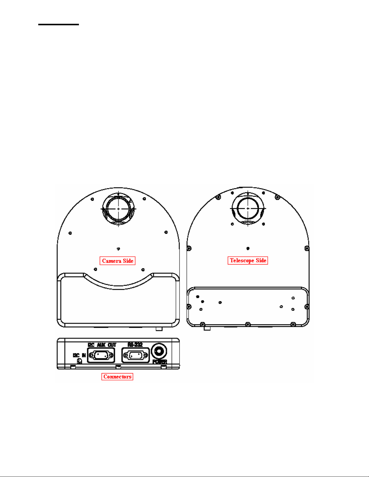
Opening the CFW-10
To open the CFW-10 remove the nine 4-40 x 3/16 Black Button-Head Cap Screws from the Telescope
Side using the supplied 1/16 inch Hex Tool. Slightly lift the aperture end of the cover and slide it away
from the connectors, allowing the connectors to clear the face plate. At this point you can insert filters
into the carousel or attach the CFW-10 to the camera. Note that the filter positions are marked with a
Page 2

CFW-10 Operating Manual
number adjacent to each position. To reassemble the CFW-10 reverse the procedure, sliding the cover
into place and replacing the nine screws.
Attaching the Windowed Version to an SBIG Camera
The Windowed version of the CFW-10 attaches to the SBIG ST-7/8/9/10/2000 series of cameras by
replacing the camera’s front cover as described below:
1. Open the CFW-10 as described above to gain access to the mounting holes.
2. Remove the camera’s front cover by removing the six Flat Head Philips screws holding it in
place. Set the cover aside. Minimize the amount of time the camera is open to keep the interior
dry, hopefully to less than 10 minutes.
3. Place the CFW-10 housing over the camera, making sure the O-Ring remains seated.
4. Attach the CFW-10 to the camera using six of the supplied 4-40 x 3/16 inch Button Head Cap
Screws. We recommend you tighten the screws in two steps, making them finger tight on the
first pass then cinching them down on a second pass. This helps insure the O-Ring remains
seated.
5. Plug the CFW-10’s dangling cable into the camera’s I2C-AUX port and tighten the thumb screw
retainers. The RS-232 connector is not used in this configuration.
6. Reassemble the CFW-10.
7. Remove the T-Thread D-Block from the camera’s original cover and attach it to the Telescope
Side of the CFW-10 using the four 4-10 x 3/8 inch Flat Head screws that held it in place on the
camera.
8. At this point the Camera is ready for use. However the desiccant will need 4 to 24 hours to fully
dry the chamber back out so that the CCD doesn’t frost. When you apply power to the camera
the CFW-10 should rotate to the home position.
9. You can use CCDOps to control the CFW-10 by selecting “CFW-10” in the Setup command in
the Filter menu. You can also customize the names of your filters.
Attaching the Windowless Version to an SBIG Camera
The windowless version of the CFW-10 attaches to the SBIG ST-7/8/9/10/2000 series of cameras by
replacing the T-Thread D-Block as described below.
1. Open the CFW-10 as described above to gain access to the mounting holes.
2. Remove the T-Thread D-Block from the camera’s original cover and set the flat head screws
aside.
3. Attach the CFW-10 to the camera’s face plate using the four supplied 4-40 x 3/16 inch Button
Head Cap Screws.
4. Attach the T-Thread D-Block to the Telescope Side of the CFW-10 using the four 4-10 x 3/8
inch Flat Head screws that held it in place on the camera.
5. Connect the CFW-10’s RS-232 port to your computer’s serial port using the supplied cable.
6. Connect the CFW-10’s Power Jack to a 12 VDC source. US customers are supplied with a 12V
DC at 2 Amp Wall Transformer. If you provide your own source of 12V the mating connector is
the locking model Switchcraft S760K and the connector is wired Center Positive.
7. When powered up, the CFW-10 will rotate to the home position, stopping at Filter 1.
8. At this point you can use CCDOps to control the CFW-10 by selecting “CFW-10 (Serial) in the
Setup command in the Filter menu or use SBIG’s stand-alone CFW10.EXE program or thirdparty software such as CCDSoft or MaximDl.
Page 2
Page 3

CFW-10 Operating Manual
Attaching an AO-7 to the CFW-10
The AO-7 can attach to the Telescope Side of the CFW-10 as described below:
1. Disassemble the AO-7 by removing the four long screws from the back.
2. Open the CFW-10 as described above to gain access to the mounting holes.
3. Attach the AO-7’s Right-Angle mount to the Telescope Side of the CFW-10 using the four 4-40
x 3/8 inch Pan Head screws supplied with the AO-7.
4. Reassemble the CFW-10 and AO-7.
5. Connect the AO-7’s dangling connector to the camera’s AO/CFW/SCOPE connectors or use our
DRC ribbon splitter cable or the more advanced Telescope Port Splitter accessory to connect
both the AO-7 and the Autoguiding cable.
6. At this point you’re ready to run the CFW-10 and AO-7.
Connecting the Autoguiding Cable
Users of the older model CFW-8/8A used to plug their Autoguiding cable into the back of the CFW-8
connector. That’s because the CFW-8 connected to the camera’s AO/CFW/SCOPE connector where
you would normally plug the Autoguiding cable. The CFW-10 connects to the USB camera’s I2C-AUX
connector leaving the AO/CFW/SCOPE connector available. So the question is: How d you connect a
tracking cable with RJ-11 connectors to the 9-pin AO/CFW/SCOPE connector? The answer is: By
using the RC-7 adapter which came with your camera. If you’re also using an AO-7 then you need to
split the AO/CFW/SCOPE connector using our DRC ribbon splitter cable or the more advanced
Telescope Port Splitter accessory.
General Notes
1. Custom software developers can learn about how to control the CFW-10 and download a
CFW-10 Developers kit from our Software Developers web page accessible from our home page
<www. sbig . com>.
2. SBIG may develop new accessories that attach to the I2C AUX OUT connector, such as a new
model AO-7. That’s why this connector is provided. It allows you to daisy-chain I2C based
peripherals.
Page 3
 Loading...