

SBIG AllSky-340,AllSky-340C Operating Manual

Operating Manual
AllSky-340 and AllSky-340C
CCD Cameras
Santa Barbara Instrument Group
147A Castilian Drive
Santa Barbara, CA 93117 USA
Phone (805) 571-7244 Fax (805) 571-1147
Web: www.sbig.com E-mail: sbig@sbig.com

Note: This equipment has been tested and found to comply with the
limits for a Class B digital device pursuant to Part 15 of the FCC Rules.
These limits are designed to provide reasonable protection against
harmful interference in a residential installation. This equipment
generates, uses, and can radiate radio frequency energy and if not
installed and used in accordance with the instructions, may cause
harmful interference to radio communications. However, there is no
guarantee that interference will not occur in a particular installation. If
this equipment does cause harmful interference to radio or television
reception, which can be determined by turning the equipment off and
on, the user is encouraged to try to correct the interference by one or
more of the following measures:
• Reorient or relocate the receiving antenna.
• Increase the separation between the receiver and the equipment.
• Connect the equipment into an outlet on a circuit different from that
to which the receiver is connected.
• Consult the dealer or an experienced radio/TV technician for help.
Shielded I/O cables must be used when operating this equipment. You
are also warned, that any changes to this certified device will void your
legal right to operate it.
_________________________________________________________
Operating Manual for Allsky-340, AllSky-340C CCD Cameras.
Revision 1.2 June 30, 2009
Copyright © 2009 Santa Barbara Instrument Group, Inc.

1
TABLE OF CONTENTS
INTRODUCTION AND OVERVIEW:.......................................... 2
MECHANICAL IMPLEMENTATION:........................................ 4
INITIAL SETUP AND FOCUSING:.............................................. 5
F
OCUS, TILT AND CENTERING ADJUSTMENTS: ............................... 7
S
ETTING UP THE SOFTWARE FOR LOGGING ALL SKY IMAGES TO
YOUR
PC OR THE INTERNET: .......................................................... 8
I
NSTALLING FIRMWARE UPDATES FOR THE ALLSKY340:............... 8
M
ISCELLANEOUS ISSUES: ............................................................... 9
ALLSKY-340 SOFTWARE........................................................... 11
M
ENUS ......................................................................................... 11
Setup Menu ............................................................................. 11
Display Menu.......................................................................... 12
Commands .............................................................................. 12
W
INDOWS AND DIALOGS.............................................................. 13
Main Window.......................................................................... 13
Status Bar................................................................................ 15
Serial Port Setup Dialog......................................................... 15
Dark Subtraction Setup Dialog............................................... 17
Still Images Setup Dialog........................................................ 17
Movies Setup Dialog ............................................................... 19
AVI Video Compression Setup Dialog .................................... 21
FTP S
ETUP DIALOG...................................................................... 21
Dialog Entries......................................................................... 22
Heater Schedule Setup Dialog ................................................ 22
Color Balance Dialog............................................................. 23
F
URTHER HELP............................................................................. 24
Contacting SBIG..................................................................... 24
APPENDIX A: BLUETOOTH RS-232 OPERATION .............. 25
APPENDIX B: CONNECTORS .................................................. 35
APPENDIX C: TYPICAL SPECIFICATIONS.......................... 36
Introduction and Overview:
SBIG’s new All-Sky camera, the AllSky-340, is SBIG’s
third version of a weatherproof AllSky camera for monitoring
weather conditions. The first had to be obsoleted when we stopped
production of the ST-237A, and the second went obsolete when the
lens we were using became unavailable, with no suitable replacement.
The third version is our best one yet! The sensor is the Kodak KAI340 CCD, with 640x480 pixels, 7.4 microns square, and a high gain
output stage for excellent sensitivity. The camera containing the
CCD is our SG-4 Smart Guider camera, our new autonomous guide
camera that is also available.
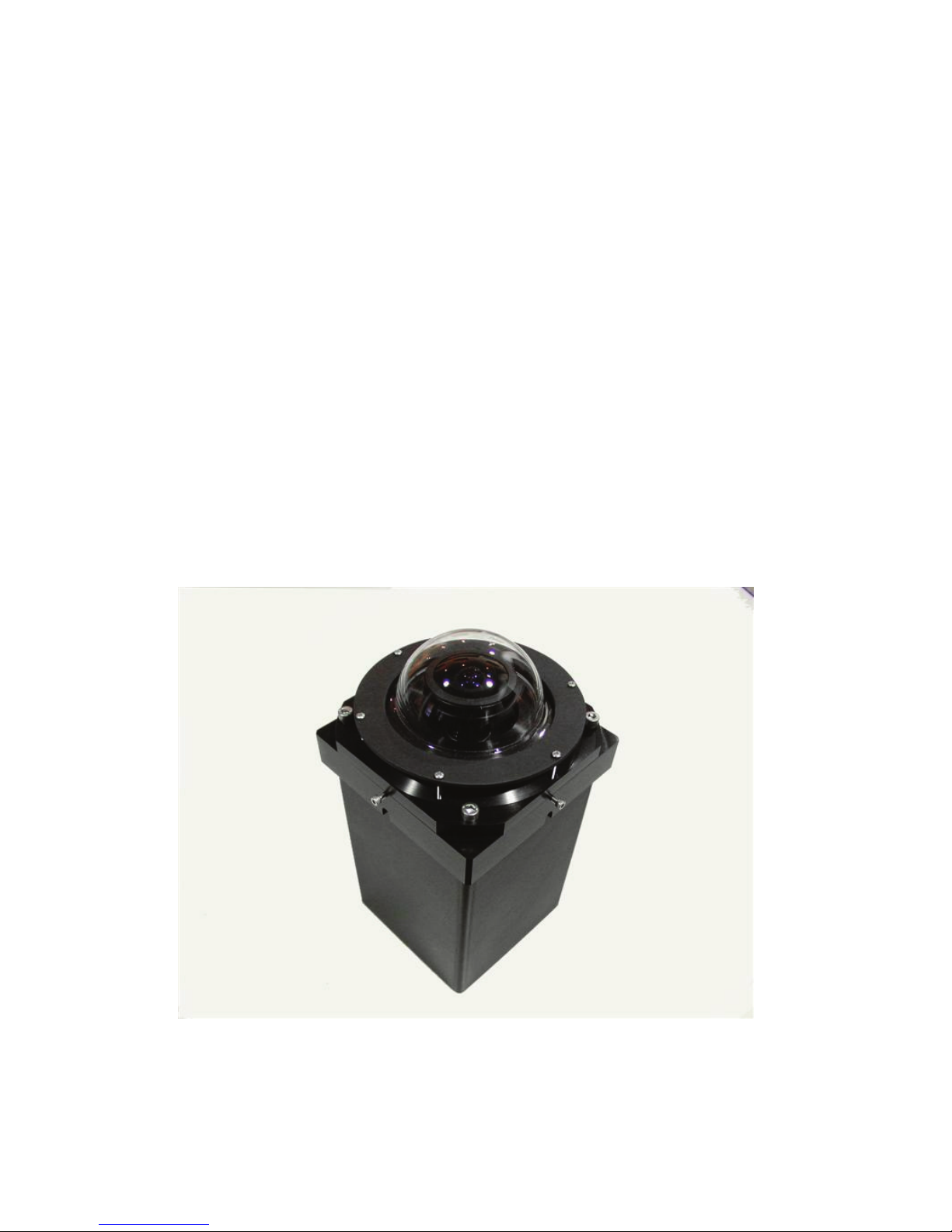
The All Sky 340 camera, illustrated below in Figure One,
incorporates the SG-4 Camera inside an aluminum enclosure with an
acrylic dome to protect the fisheye lens. The fisheye lens
recommended by SBIG is Fujinon’s new FE185C046HA-1, with a
1.4 mm focal length, F/1.4.
Figure One: All Sky 340 Camera
2
The image quality is excellent wide open, all the way to the horizon.
Figure Two shows an All Sky camera image with the Fujinon lens
and KAI-340 CCD. The exposure was 60 seconds from a light
polluted backyard – the first quarter moon had just set behind the
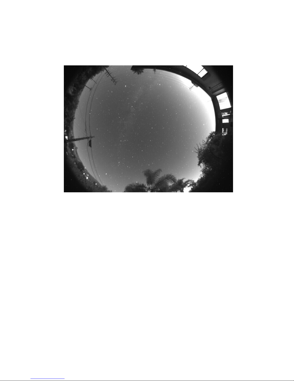
roof. The field of view is slightly greater than 180 degrees in the
horizontal direction.
Figure Two: All Sky Camera Image
The image illustrated was taken using a monochrome sensor.
The unit is also available with a color CCD sensor. Note: with a
monochrome sensor the daylight images are not particularly good –
the sun and bright clouds saturate large portions of the field of view.
With a color sensor the sun has a strong blooming streak top to
bottom in the image, which mars the aesthetics of the image, but it
still works well for cloud detection.
The new All Sky camera has some very interesting features
that make it much more versatile than our previous offerings. First of
all, it has an RS-232 link to the PC for control and image download.
While this interface is very slow in comparison to USB, it will
tolerate 150 foot (30 meter) cable runs. Or, you can throw away the
cable and use a bluetooth wireless link with an optional inexpensive
adapter. And, the unit is low power and can be powered by a solar
array (also optional) so you don’t need any wires AT ALL running
from your PC to the camera! The beauty of this is now the unit can
be located where it has a good view of the sky, instead of good access
to a power plug or PC. Your roof is now the preferred location,
above the trees and neighbor’s houses.
3

4
By actual test, an RS-232 link, using a USB to RS-232
adapter running at 460.8 Kbaud, with a 150 foot long cable,
downloads a full image reliably in ~15 seconds. At 115.2 Kbaud a
full image takes ~60 seconds. Bluetooth wireless adapters will
typically run at 115 Kbaud, and the one we have tried here worked
reliably at a distance of 75 feet. With wireless links, one must
minimize the number of walls you have to pass through. Each wall (2
layers of dry wall or wood) costs about a factor of two in signal and
range.
The All Sky camera can take an image while transmitting,
so with exposures longer than the download time the camera is only
insensitive for the length of the readout of the CCD, which takes
place in less than 1 second to an internal memory buffer in the
camera. As a result, the camera is excellent for meteor detection. Its
field of view is wider than our previous meteor camera, so it should
see many more meteors near the horizon. One other plus – the
software can run continuously in the background while you use your
computer for other tasks. At these download rates the computer
workload is so slight your applications won’t even notice. It will not
interfere with regular imaging using the same PC. The All Sky image
is there when you want to view it.
Mechanical Implementation:
The housing is lustrated in Figure One. The fisheye lens is
mounted to a plate which can be translated, tipped, and focused
relative to the CCD, so the full resolution of the lens can be achieved.
This plate is also heated, to keep the lens free of condensation. The
heat rises into the acrylic dome, warming it and keeping off the dew,
and drying off raindrops. The inexpensive acrylic dome is easily
replaced by removing a few screws, allowing for routine replacement
in the field as the dome suffers the inevitable scratches and damage
due to sunlight, windblown dust and disrespectful birds. The
prototype shown in Figure one is black – the production version has a
white body so it doesn’t get as hot in the sun. The unit is 5.5x5.5x11
inches in size (14x14x28 cm). The cables are designed to exit out the
bottom of the unit so the connectors stay dry. If one runs the cables
into a building make sure the last section of cable before entering the
structure angles upward so water doesn’t drip down the cable into the
wall. The housing has holes in the side so it can be easily mounted to
a post with ¼-20 lag screws, or ¼-20 bolts.
Initial Setup and Focusing:
As with all of our products, we recommend a user become
familiar with the product indoors in a well-lit setting before venturing
outside. A rooftop may be the best place to mount an All Sky
camera, but it is the worst place in the world to be installing software
and learning camera operation, particularly in the dark. Also, do not
try to go to Bluetooth immediately – start with a wired connection.
Begin by installing the software to your PC. Make sure you have
administrator privileges on the PC, and insert SBIG’s software disk.
A screen should pop up in a few seconds. Select “SG-4, AllSKy340” software to install and, on the next screen, select “Install
AllSKy-340”. The software should install automatically. You might
also choose to install CCDOPS at this time. (Note – CCDOPS will
not communicate with the AllSky 340. It can display FITS files
saved with the AllSky Program, but that is all.) Next, connect the 9pin serial cable between a serial port on your PC and the AllSky
Camera’s RS-232 port. If your computers does not have a serial port,
one can be easily implemented using an USB-RS-232 converter. One
we have had good luck with is the FTDI US232R-10-BLK, but there
are many to choose from. We stock this converter if you wish to
purchase it, and the drivers are also on the software disk. Finally,
hook up the power to the AllSky camera, making sure the connector
is well seated and does not wiggle (which would cause the power to
be intermittent). Power up the unit, and flip the small recessed Power
On/Off switch toward the lettering. The red LED in the switch
should light steadily.
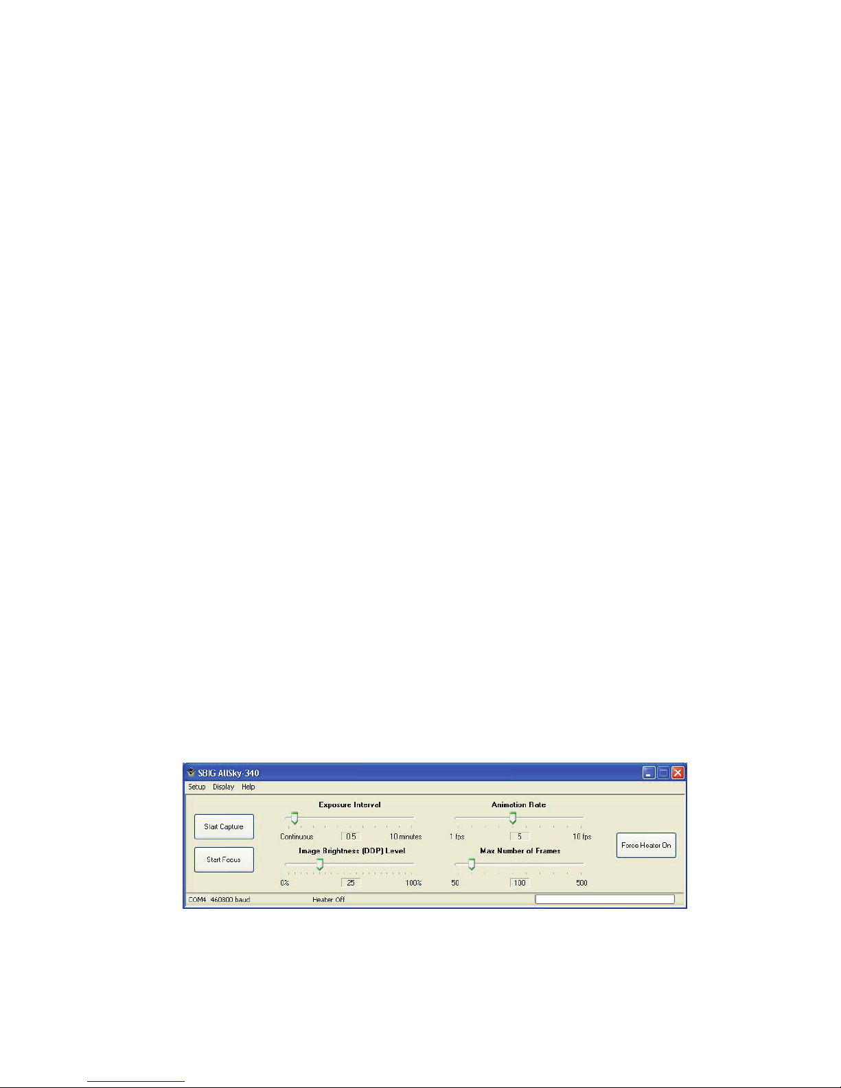
Launch the SBIG AllSky340 software. You will see the
screen shown in Figure Three as well as one or two image windows.
Figure Three AllSky340 Main Software Screen
The first item to try is under the Setup menu item - Serial Port. This
will open up a window you can use to test the RS-232 link. There
you can enter the COM port and the baud rate, and hit TEST. If you
5

6
are successful, a box will pop up saying so. Note that when the
window opens it automatically tries to communicate with the camera
on the selected COM port, starting at 9600 baud and working it way
up in speed. If it successfully finds a camera it tells the camera to
switch to a higher baud rate and try that. If it cannot communicate at
the higher baud rate, it reverts back to the last successful baud rate.
This all happens automatically without user control. The reason you
need to know this is if you try the camera indoors on a computer with
a fast link, and then move outside to a laptop with a slower link, the
camera will not communicate. When this happens, the camera can be
reset to 9600 baud by turning off the power, and holding down the
Guide On/Off button while powering up the camera, and holding it
until the status LED turns red. Then when the Serial Port command is
run it will start out at a baud rate that will work on any machine
(9600).
Once you have successful communication, start the focus
operation by clicking the Start Focus button on the Main Software
Screen. The camera will start out by taking very short exposures and
gradually working its way up to longer exposures until it senses
adequate signal levels. The images displayed are binned 2x2 to speed
this process up. When you start this command, you should have the
AllSky camera in a well-lit room with something on the ceiling above
it you can focus on (other than a way too bright light bulb!). When
an image with adequate brightness is collected the software will ask
you to select a region to focus on. Pick a structured area in the center
half of the frame and the software will go into a rapid focus mode
zoomed in on that area. Focus the area carefully and, when done,
select STOP FOCUS to end the process and return to the Main
Screen.
Once you have a pretty good focus, you might want to select
START FOCUS again and work on the centering. When that looks
good, you can select the START CAPTURE command which will
capture and display full resolution images. You can use these images
to set the final focus. Adjusting for best focus across the CCD by
tilting the lens is best done outside with the unit looking up at a star
field. Focusing the AllSky camera can take some time to get perfect,
so don’t be in a rush to get through this step. Fortunately focus holds
over temperature changes fairly well. Sometimes the day/night
temperature cycling can initially cause some focus shift, but it should
settle down after that.
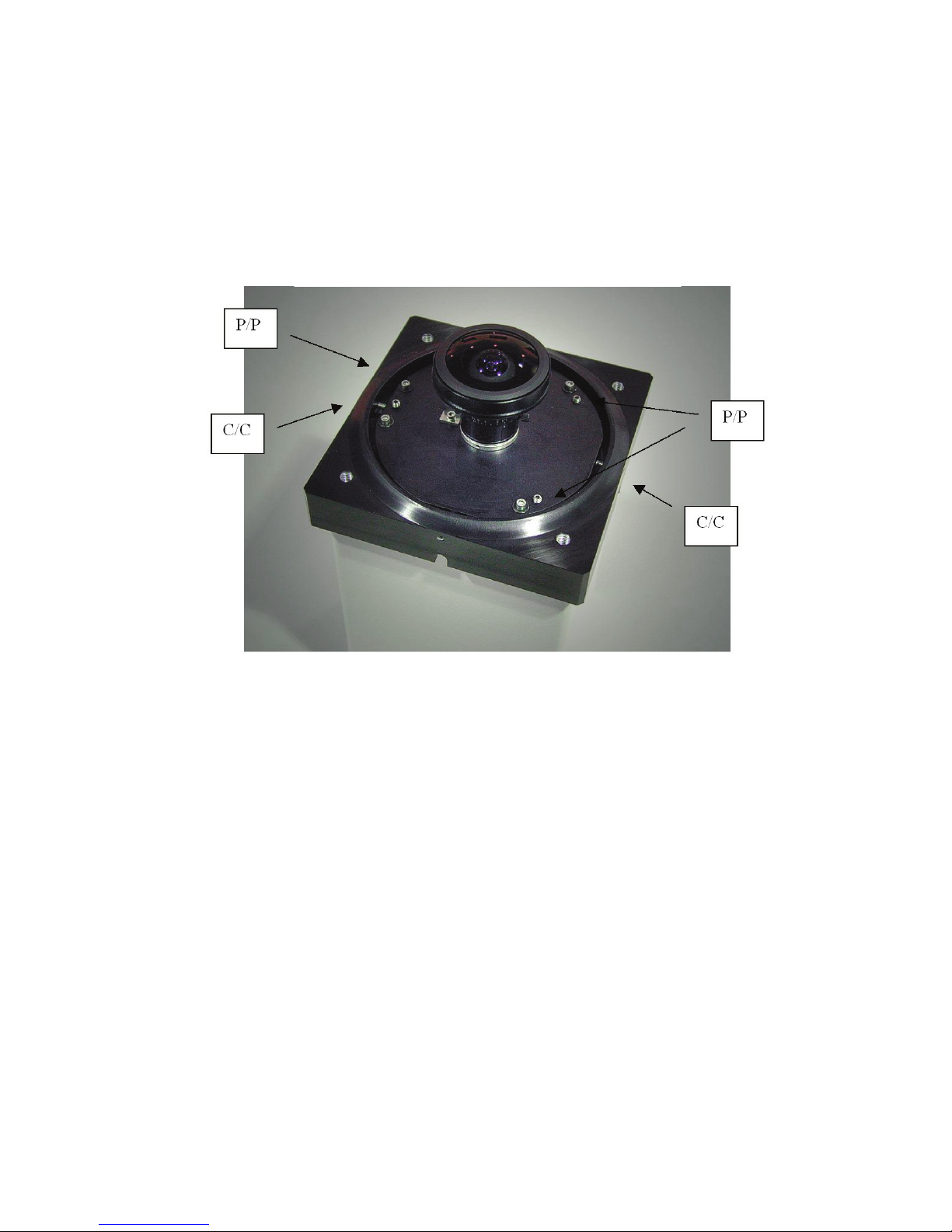
Focus, Tilt and Centering Adjustments:
The focus, tilt and centering adjustments are shown in
Figure Four. If you have the lens installed at the factory it will be
close when you get it, but it can be tedious getting it perfect.
Figure Four: Focus, Tilt and Centering Adjustments
Focus can be adjusted with the three sets of push/pull screws
around the periphery of the lens plate (marked P/P). They are
adjusted by loosening one screw of the pair slightly, and tightening
the other. You are trying to set focus to an accuracy of about 0.001
inch (25 microns), which is only 1/25
th
turn of the screw, so a very
delicate touch is required when close. To set the centering, use the
push/pull screws labeled C/C around the edge. Note that this
adjustment can only be done when the focus screws are a little loose
so the plate can translate. The proper order of adjustment is:
A) Inside, in a room:
1) Set the focus close to correct in the center of the image
2) Translate the lens so the centering is quite good
3) Set the focus in the center carefully
B) Outside, under the stars
1) Adjust the tilt of the lens plate to get the best focus
7

8
across the image
2) Tighten up the screws, but do not over tighten them
3) Check focus in the center again
Setting up the software for logging All Sky images to
your PC or the Internet:
The ABIG AllSky 340 software supports a variety of
logging options you can use to monitor sky conditions. The simplest
is to just have it running in the background on your computer, and
when you want to see the latest still image, merely maximize the
application. Other options are to log all images as JPEG and FITS
files to your disk, to log a JPEG or FITS image to a fixed location on
your disk over and over, to transmit the files to a web site where
others can download them, to create movies out of these files saved
on your disk for visualization on your PC or to be uploaded to an FTP
site, etc. The most useful for users who want to share their sky
information with others is just to write a JPEG to a fixed web address
automatically. If you have a web page with FTP access, the software
will allow you to repetitively write the latest image to a location there
provided you have your user name and password. See the AllSky
Software Section of this manual for more information on these
options.
Installing Firmware Updates for the AllSky340:
The AllSKy340 can be easily reprogrammed in the field using the
following procedure:
1) Within the AllSky340 program, select HELP from the top
task bar menu, and select ABOUT,
2) Click the REPROGRAM button,
3) Browse to the new program file (.BFx),
4) Select “OK”
At the end of reprogramming turn power off to the camera and turn it
back on to force a fresh boot of the camera.

9
Miscellaneous Issues:
The primary purpose of this camera for most users will be
detection of cloud cover, both during day and night, but primarily
night, at a remote site. Under massive saturation conditions, such as
the sun in the field of view, a vertical column of saturated pixels will
be seen in the image. This appears to be unavoidable at our shortest
exposure of 50 microseconds. When thin clouds are near the sun it
can blossom out horizontally, and be annoying. We feel that, while
this is cosmetically irritating, it does not compromise the primary
purpose of this device much. The monochrome sensors are more
affected by this due to their approximately 4X greater sensitivity.
There is a vent hole underneath the lens plate to allow the
enclosed space under the dome to ventilate to the outside air. There
may be conditions where fogging can appear inside the dome under
rapidly changing atmospheric conditions but it should dissipate
quickly (within an hour) due to the action of the heater. The heater,
when on, is injecting >4 watts into the lens plate to keep the lens clear
of moisture and also the dome, as the heat rises from the plate. This
power level has worked well here in Santa Barbara, which is really
prone to fog due to the presence of the ocean – we think it will work
well for most users. The heater is seldom needed in the day since the
sun heats up the interior of the dome, but will hurt nothing if left on.
The heater schedule can be set within the software mainly to conserve
power for solar powered installations.
Be sure to ground the case. Do not assume the case is
grounded through your PC RS-232 port. At SBIG we have had many
cameras come in that were destroyed by lightning, but at least 4 times
more than that were not actually struck, but simply in the presence of
high electric fields when lightning is in the area. If the camera is on
your rooftop it becomes a lightning rod unless your installation is
solar powered and has a wireless connection. If it is on a roof, and
you are running an RS-232 cable to your PC, we recommend you use
an RS-232 isolator, such as the B&B Electronics 9SPOP2 (www.bb-
elec.com). It slows your baud rate to 115,200. There may be faster
ones out there, but we are not familiar with them.
Since the KAI-340 CCD used in the AllSky 340 camera is
not cooled, dark frames are required on a regular basis to cancel out
the pattern noise due to hot pixels scattered across the CCD. For this

10
reason the AllSky 340 camera has a built-in mechanical shutter. The
software contains a control to schedule how often a dark frame is
collected. A new dark should be collected if the ambient temperature
changes by one degree, so each user may have different situations at
their site. We recommend a new dark at least every 15 –30 minutes
or so.
 Loading...