

Page 1
USER MANUAL
(ENGLISH)
SBGuidance 4.0.0
Software operation
Page 2
Preface
Page 2/70 | May 2015 | 2.0
Name of device:
Type designation:
Serial no. of manifold:
Serial no. of terminal:
Serial no. of sensor box:
Serial no. of dynamIQ:
Year of manufacture:
Options:
Installed software module:
1
2 3
4
5
WARNING!
This user manual must be available for
people who operate, service and repair
this product.
Your dealer:
Page 3
Preface
Page 3/70 May 2015 I 2.0
Preface
This operating manual is intended for those
persons who are competent to operate the
SBGuidance software. The operating manual
contains important information and instructions
that must be complied with when setting up,
operating and servicing the SBGuidance
system. This operating manual must therefore
be read and understood by competent persons
BEFORE the system is set up and must always
be kept in the close vicinity of the machine.
The greatest possible care has been taken in
the compilation of the manual. However, SBG
Precision Farming accepts no liability for any
errors or incomplete information contained in
this document.
In this manual several terms are used that are
intended to draw attention to particular aspects
of the SBGuidance System and its operation.
Tip:
Provides recommendations on how
certain activities can be performed much
easier.
Please note!
Indicates certain problems that the user
should take note of.
Caution!
Indicates that the machine can be
damaged.
Remarks or queries can be submitted to:
[email protected]
Neither SBG Precision Farming nor any of
its suppliers may be held liable for any
injury or damage to property that may arise
from the use of the system SBGuidance
System.
Warning!
Indicates a risk of injury.
Page 4
Page 4/70 | May 2015 | 2.0
Disclaimer
Disclaimer
Warning!
The safety instructions contained in the
operating manual of the tractor or the
machine must be complied with at all
times.
Warning!
It is strictly forbidden to use the
SBGuidance system on public roads.
Warning!
It is strictly forbidden to leave a machine
being operated with or without the
SBGuidance steering system activated.
Warning!
In order to prevent personal injury or fire,
defective or blown fuses may only be
replaced by fuses of the same type and
amperage.
Warning!
The SBGuidance steering system is not
capable of identifying and avoiding
obstacles. Any obstacles along the
driving path must be avoided by the
driver.
Caution!
Always start the machine first, before
activating the SBGuidance steering
system in order to prevent the
occurrence of a peak voltage.
Caution!
Only touch the touch-screen with your
finger or with a special touch-screen
stylus. Sharp objects may cause
irreparable damage to the touch-screen.
Caution!
Only clean the screen using a damp
cloth. Never use caustic or other
aggressive substances.
Please note!
If the terminal is not used for a long
period, better remove the terminal from
the tractor and store in a heated
environment. This will extend the life
span of the electronic components.
Please note!
To prevent theft, it is better to not let the
terminal and GPS-antenna unattended in
the tractor on the field.
Warning!
Only allow authorised persons to operate
the system. Authorised persons include:
Persons who have read and understood
the operating manual and who are both
physically and mentally fit to operate the
system.
Page 5

Page 5/70 May 2015 I 2.0
Components
Table of contents
Preface .......................................................................................................................................... 3
Disclaimer ..................................................................................................................................... 4
1. Components ............................................................................................................................ 7
1.1. Viper 4 terminal ................................................................................................................... 7
1.2. GeoStar 250 terminal .......................................................................................................... 8
1.3. GeoStar 200-Terminal ......................................................................................................... 9
1.4. Slingshot field hub ............................................................................................................. 10
1.5. GeoConnect 3G ................................................................................................................ 11
1.6. GPS antenna ..................................................................................................................... 11
1.7. Terminal fixture ................................................................................................................. 12
1.7.1. RAM-D connection ..................................................................................................... 12
1.7.2. RAM-C connection ..................................................................................................... 12
1.8. Connecting cables to terminal ........................................................................................... 13
2. System start-up ..................................................................................................................... 15
2.1. Conditions of use .............................................................................................................. 15
2.2. SBGuidance loader ........................................................................................................... 16
3. Main menu ............................................................................................................................. 19
3.1. Soft-keys ........................................................................................................................... 19
3.2. Information in the top menu bar ........................................................................................ 20
4. Fields ...................................................................................................................................... 21
4.1. Creating a new field .......................................................................................................... 21
4.1.1. A+ field ....................................................................................................................... 22
4.1.2. A-B field ...................................................................................................................... 24
4.1.3. Contour field ............................................................................................................... 26
4.2. Defining a new operation .................................................................................................. 29
4.3. Loading fields .................................................................................................................... 33
4.4. Load fast ........................................................................................................................... 33
4.5. Edit fields .......................................................................................................................... 34
5. Settings .................................................................................................................................. 35
5.1. Vehicle settings ................................................................................................................. 35
5.1.1. SBGuidance Auto ....................................................................................................... 36
5.1.2. SBGuidance Side-Shift ............................................................................................... 40
5.1.3. SBGuidance TWIN/Discs ............................................................................................ 42
5.1.4. SBGuidance TWIN/Side-Shift ..................................................................................... 43
5.1.5. SBGuidance Vario-plough .......................................................................................... 43
5.2. GPS set-up........................................................................................................................ 45
Page 6
Page 6/70 | May 2015 | 2.0
Content
5.2.1. Receiver ..................................................................................................................... 45
5.2.2. Modem ........................................................................................................................ 48
5.3. System set-up ................................................................................................................... 52
5.4. SmartSwitch (Section Controller) ...................................................................................... 53
5.5. VRA (Variable Rate Application) ....................................................................................... 53
6. Info ......................................................................................................................................... 55
6.1. GPS info ............................................................................................................................ 55
6.1.1. Position ....................................................................................................................... 55
6.1.2. Orientation .................................................................................................................. 57
6.2. Field info ........................................................................................................................... 59
6.2.1. Details......................................................................................................................... 59
6.2.2. Work data ................................................................................................................... 59
6.2.3. Edit operation ................................................................................................ ............. 60
6.3. System info ....................................................................................................................... 60
6.3.1. Error messages .......................................................................................................... 60
6.3.2. Version ....................................................................................................................... 61
6.3.3. Debug ......................................................................................................................... 61
6.3.4. Licence ....................................................................................................................... 62
6.4. Internet info ....................................................................................................................... 64
6.5. CAN info ............................................................................................................................ 64
7. Registration ........................................................................................................................... 65
7.1. Points of interest ............................................................................................................... 65
7.2. Lines ................................................................................................................................. 66
7.3. Height ................................................................................................................................ 68
7.4. Crop registration ................................................................................................................ 69
Page 7
Components
Page 7/70 May 2015 I 2.0
2 3 4
5
6 7 8 9 10
11
12
13
14
1. Components
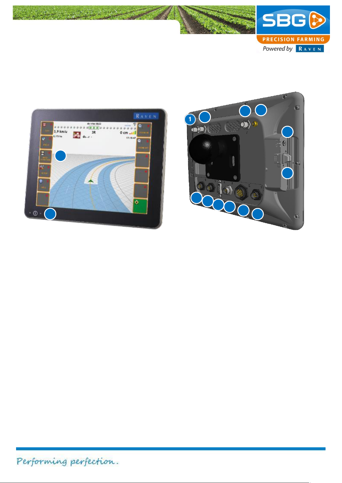
1.1. Viper 4 terminal
Figure 1 Viper 4 terminal
In Figure 1 all Viper 4 terminal connections are
numbered.
1. Radio (optional): coax small (TNC)
2. GPS-antenna 2: coax small (TNC).
Connection for the second GPS-antenna
(GPS2).
3. GPS-antenna 1: coax small (TNC).
Connection for the main GPS-antenna
(GPS1).
4. WiFi-antenna: FNC
5. External audio: 3,5 mm jackplug
6. USB: 2x
7. Power: 4-pin connector for 12V power.
8. Main interface: 20-pins connector for
serial and CAN-bus communication.
9. Ethernet: 8-pin network connector.
10. External display: DVI.
11. CAN-bus: additional CAN-bus connection.
12. Camera input: camera connection (not
supported in combination with
SBGuidance).
13. Touch-screen: operations are performed
exclusively via a colour touch-screen.
14. Main power switch
Page 8
Page 8/70 | May 2015 | 2.0
Components
2 3 4
7 8 9
10
11
12
13 5 6
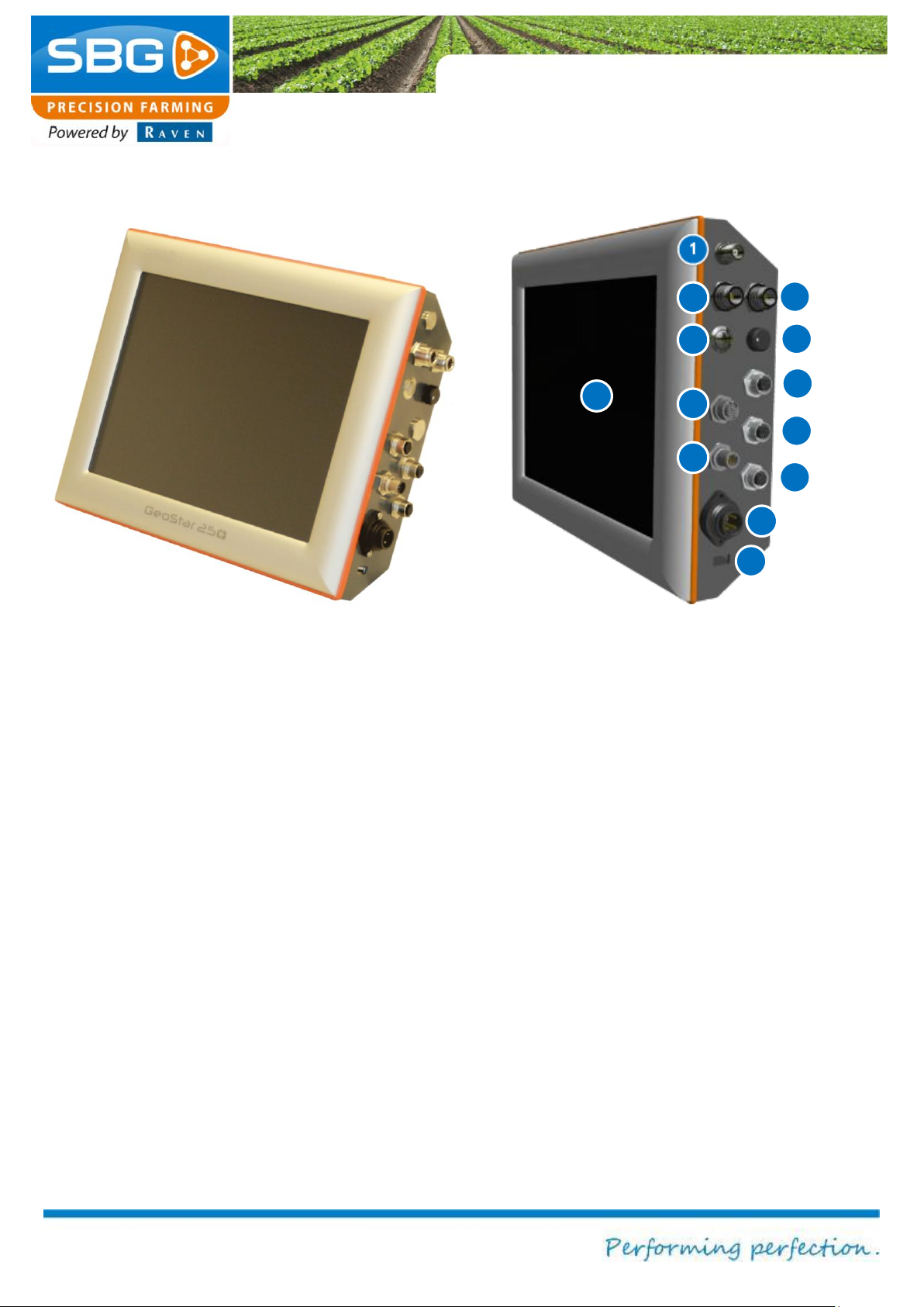
1.2. GeoStar 250 terminal
Figure 2 GeoStar 250 terminal
In Figure 2 all GeoStar 250 terminal
connections are numbered.
1. Radio (optional): coax small (TNC)
2. GPS-antenna 1: coax large (N).
Connection of the main antenna (GPS 1).
3. GPS-antenna 2: coax large (N).
Connection of the second antenna
(GPS2).
4. Main power switch
5. Screen dimmer
6. Ethernet 2 (optional): 4-pin connector.
7. RS-232: 17-pin serial connector for
external devices.
8. Ethernet: 4-pin network connector.
9. CAN-bus: 8-pin connector.
10. Extern modem: 8-pin connector for
external radio or UMTS modem.
11. Power: 4-pin connector for 12V power.
12. USB
13. Touch-screen: operations are performed
exclusively via a colour touch-screen.
Page 9
Components
Page 9/70 May 2015 I 2.0
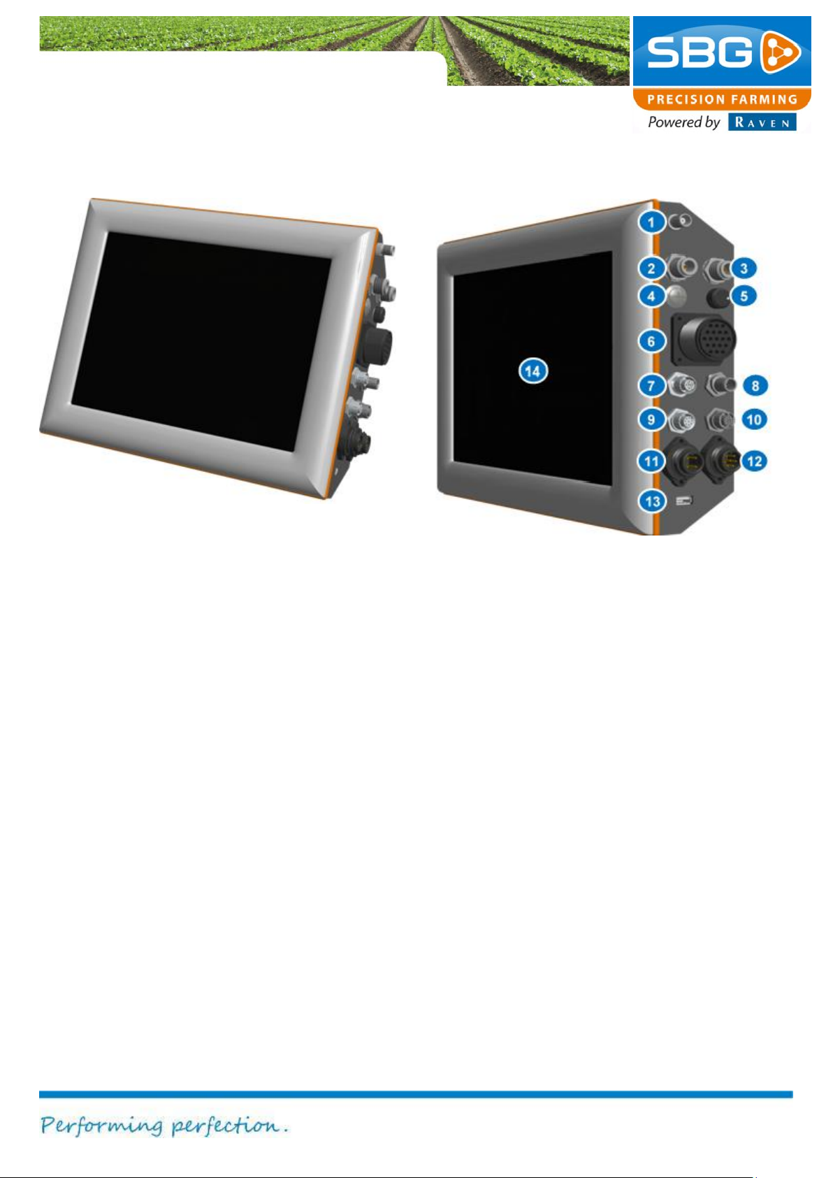
1.3. GeoStar 200-Terminal
Figure 3 GeoStar 200 terminal
In Figure 3 all GeoStar 200 terminal
connections are numbered.
1. Radio connection: coax small (TNC)
2. GPS antenna connector 1: coax large
(N). Connection of the main antenna
(GPS 1).
3. GPS antenna connector 2: coax large
(N). Connection of the second antenna
(GPS 2).
4. Main switch
5. Screen dimmer
6. Data transmission cable: 19-pin plug-
in/screw connector for the sensor box
7. Ethernet: 4-pin plug-in/screw connector
for 12V power supply.
8. CAN bus connection: 8-pin connector
9. External modem: 8-pin connector for an
external radio or UMTS modem
10. RS-232 interface: 17-pin serial plug-
in/screw connector for an external device
connection
11. Power cable: 4-pin connector for 12V
power.
12. External analogue terrain
compensation module connector: 7-pin
connector for the analogue terrain
compensation module on the implement
13. USB interface
14. Touch-screen: operations are performed
exclusively via a colour touch-screen.
Page 10
Components
Page 10/70 | May 2015 | 2.0
1 2 3 4 5
6
7
8
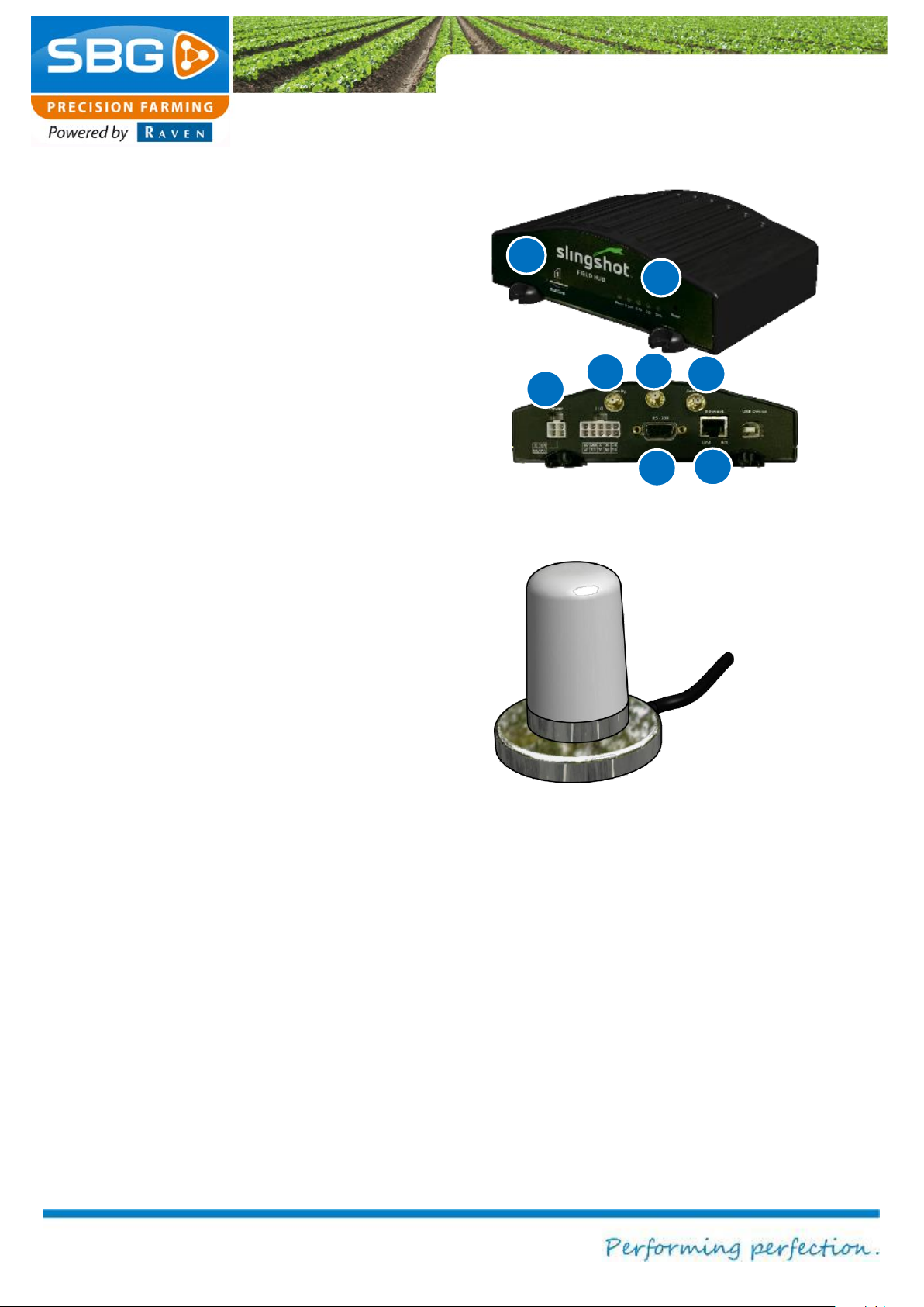
Figure 4 SlingShot field hub
Figure 5 UMTS-antenna
1.4. Slingshot field hub
To receive RTK correction data with an internet
connection a GSM-modem is required. A
SlingShot field hub is a GSM-modem with a
dual GSM-antenna possibility to be able to work
with low GSM signal strengths.
In Figure 4 all Slingshot field hub connections
are numbered.
1. Power supply
2. UMTS-antenna (diversity): see Figure 5
3. GPS-antenna
4. UMTS -antenna (main): see Figure 5
5. RS-232: COM-port for serial
communication; sends RTK correction
data.
6. Ethernet
7. SIM slot
8. LED’s: indicate information about the
status of the connection.
See for more information of the Slingshot field
hub on the Raven website:
http://ravenhelp.com/ProductSupport/Slingshot/Slingshot.aspx#manuals
Page 11
Components
Page 11/70 May 2015 I 2.0
1
2 3 4
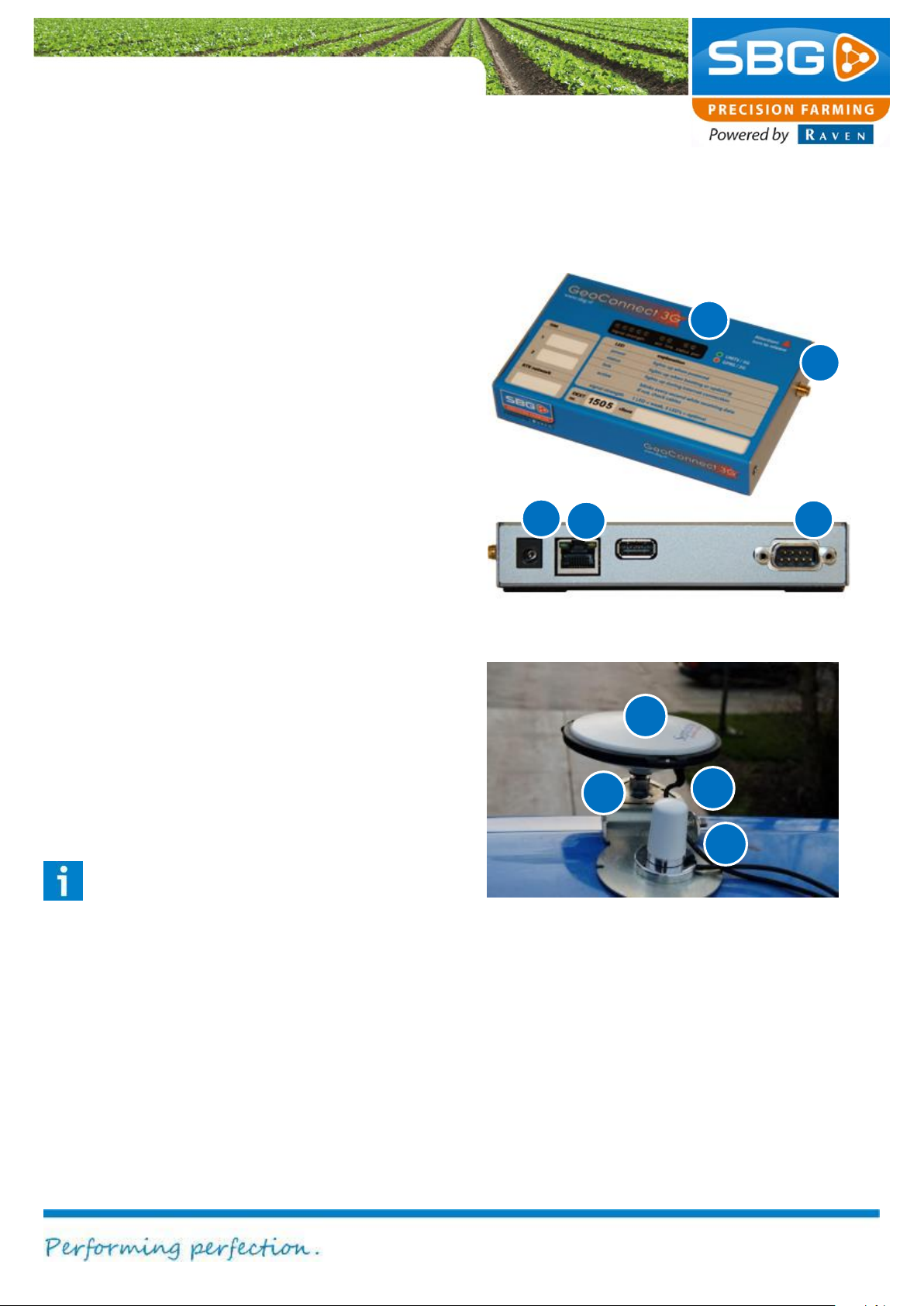
Figure 7 GPS-antenna
4
5
2 1 3
Figure 6 GeoConnect 3G-Modem
1.5. GeoConnect 3G
The GeoConnect modem is the conventional
GSM-modem, which can be used for receiving
RTK correction data via a mobile internet
connection.
In Figure 6 all GeoConnect 3G modem
connections are numbered.
1. Power supply
2. Ethernet
3. RS-232: COM-port for serial
communications
4. UMTS antenna: see Figure 5
5. LED lights: A description of the status
information can be found on the top of
the GeoConnect 3G modem.
1.6. GPS antenna
Figure 7 shows an installed GPS antenna:
1. GPS antenna
2. UNC screw (for mounting GPS
antenna)
3. Dummy connector
4. Antenna cable with coaxial
connection
Please note!
When removing the GPS antenna, the
antenna cable must always be screwed
to the dummy connector. This prevents
dirt and/or water penetrating the
connector of the antenna cable.
Page 12
Components
Page 12/70 | May 2015 | 2.0
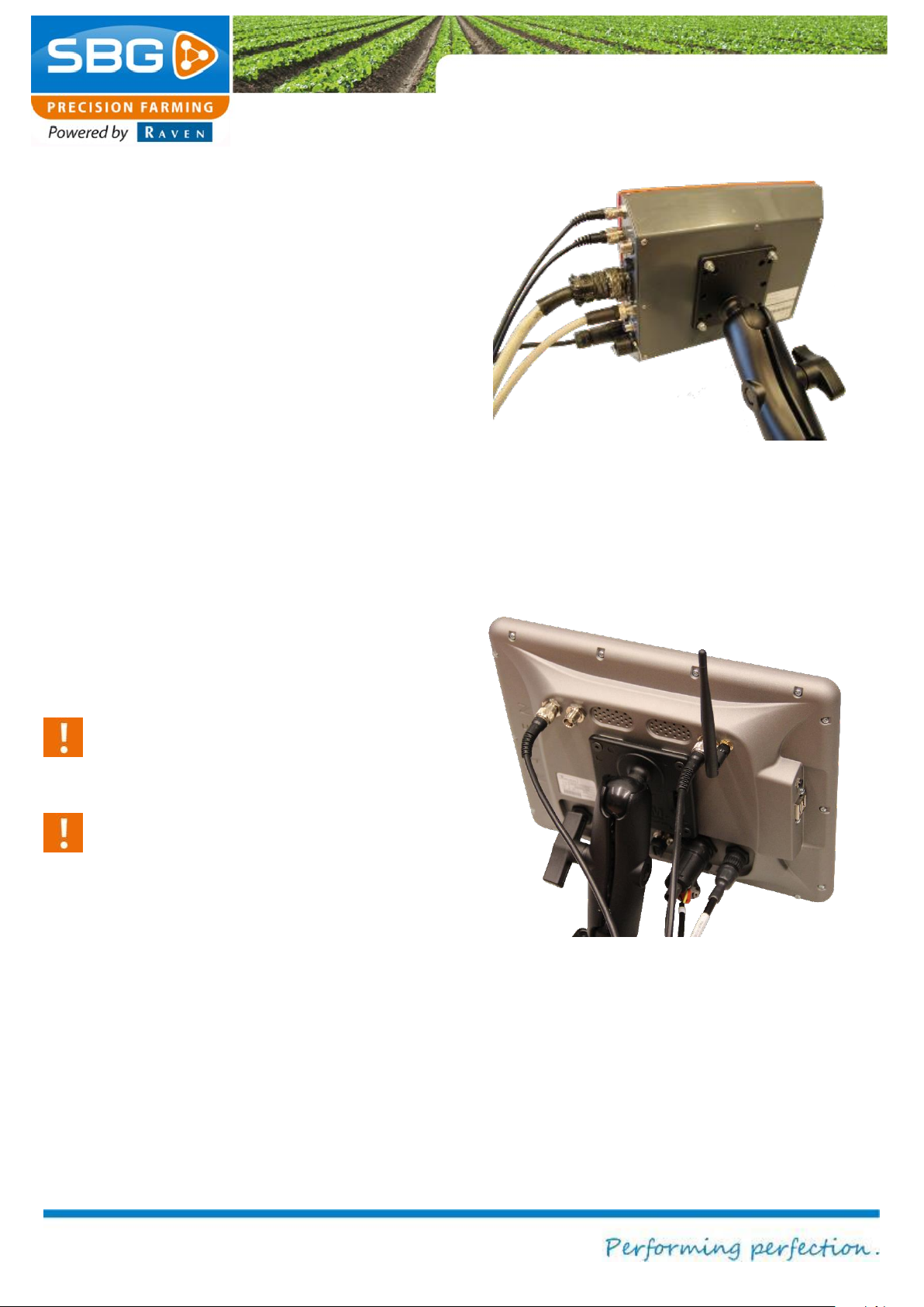
Figure 8 RAM-D connection terminal
Figure 9 Viper 4 with RAM-C connection
1.7. Terminal fixture
Various options are available for attaching and
mounting terminals. The RAM-D connection is
standard for all these terminals. The Viper 4 is
available with a smaller RAM connection (RAMC).
1.7.1. RAM-D connection
Figure 8 shows how a terminal with a RAM-D
connection is mounted. For the Viper 4,
GeoStar 200 and GeoStar 250 terminal the
RAM-D connection is standard. A Viper 4
terminal can also be shipped with a RAM-C
connection. However, for a Viper 4 terminal with
an external GSM-modem a RAM-D connection
is advised.
This type of fixture/mount allows the position of
the terminal to be adapted to the individual
needs of the user.
Caution!
Prevent the terminal from falling from the
mount when disconnecting the RAM arm.
Caution!
After connecting the terminal, always
check that the RAM arm is screwed on
tightly enough.
1.7.2. RAM-C connection
Figure 9 shows a Viper 4 terminal with RAM-C
connection. The RAM-C connection is the
smaller variant of the RAM-D connection.
Page 13
Components
Page 13/70 May 2015 I 2.0
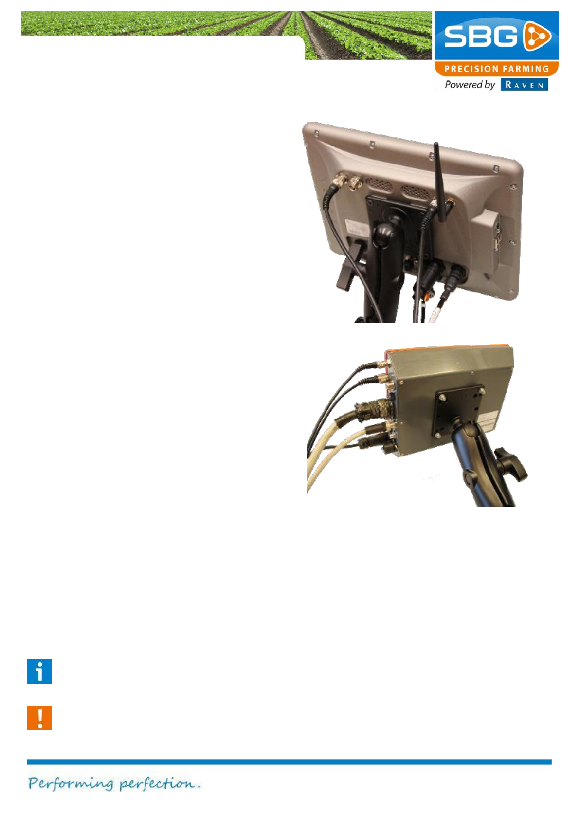
Figure 10 Connected Viper 4 terminal
Figure 11 Connected GeoStar 200 terminal
1.8. Connecting cables to terminal
Take the following steps to connect the cables
to the different terminals.
Viper 4 (Figure 10):
1. Connect the main interface cable.
2. Connect the power supply cable.
3. Mount the terminal with the RAM-
connection.
4. Connect the GPS-antenna cable(s) and
the radio/UMTS-antenna cable.
5. Mount the GPS-antenna on the UNCbolt.
6. Unscrew the GPS-antenna cable from
the dummy connector and screw the
GPS-antenna cable onto the GPSantenna.
GeoStar 200/250 (Figure 11):
1. Mount the terminal with the RAM-
connection.
2. Connect (if present) the CAN-cable.
3. Connect the data communication cable
(if present). Press firmly and screw the
connections tight.
4. Connect the external power supply
cable.
5. Connect the GPS-antenna cable(s) and
the radio/UMTS-antenna cable.
6. Connect the external analogue terrain
compensation module cable
7. Mount the GPS-antenna on the UNCbolt.
8. Unscrew the GPS antenna cable from
the dummy connector and screw onto
the GPS antenna.
Please note!
Ensure that all connectors are plugged in
straight and tightened firmly.
Caution!
Make sure that the RAM mount is firmly
secured and sufficiently tight.
Page 14
System start-up
Page 14/70 | May 2015 | 2.0
Intentionally left blank
Page 15
System start-up
Page 15/70 May 2015 I 2.0
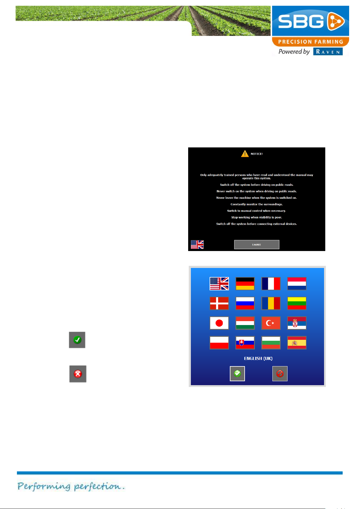
Figure 12 Conditions of use
Figure 13 Language option for conditions of use
2. System start-up
Start the terminal by briefly pressing the main
power switch on the Viper 4 or GeoStar
terminal.
The system will take about 30 sec to initialise.
2.1. Conditions of use
Before you can start to use the system, the
system screen first displays the conditions for
use (Figure 12). These conditions must be read
and accepted by the operator/user.
The conditions of use can be accepted by
tapping on I AGREE.
The language option for the conditions of use
can be selected by tapping on the appropriate
flag. Changing the language option here also
changes the language settings of the Field
Manager and Machine Manager software
applications.
The window shown in Figure 13 is then
displayed. Choose the required language by
selecting the corresponding flag and then
confirm.
Confirm (tap)
Abort (tap)
Page 16
System start-up
Page 16/70 | May 2015 | 2.0
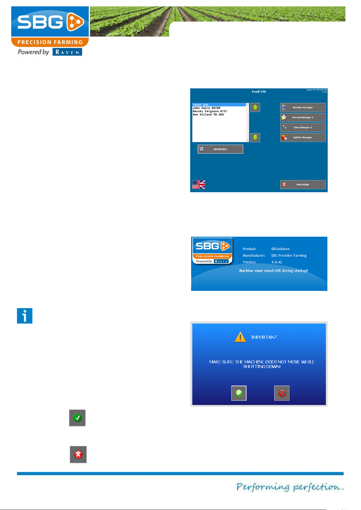
Figure 14 SBGuidance loader
Figure 15 Start-up screen
Figure 16 System exit screen
2.2. SBGuidance loader
After accepting the conditions of use, the
SBGuidance Loader (system) screen is
displayed (Figure 14).
The Loader displays all available machine
profiles (tractor and implement) loaded into the
SBGuidance system. New machine profiles
needs to be installed/added by a SBG dealer.
To exchange existing machine profiles between
terminals the SBGuidance Machine Manager
can be used.
Select the required tractor vehicle or implement
by pressing the green arrow or the name of the
vehicle or device. The device or implement
selected is then highlighted in blue and
displayed in the centre of the screen.
Press SBGUIDANCE beneath the options
window after selecting the required device. The
software will now initialise and load the
corresponding parameters and display the startup screen (Figure 15).
Please note!
The tractor must always be stationary
when the software is initialised. The
electronic terrain compensation module
will now be initialised.
To exit the system, tap on SHUTDOWN at the
bottom right of the screen. The exit screen is
then displayed (Figure 16).
Confirm (tap)
Abort (tap)
Page 17

System start-up
Page 17/70 May 2015 I 2.0
In addition to the device options, the Loader
also provides access to the following
applications:
Base Manager: This software allows a
base station to be selected, added,
changed or removed.
Field manager: An USB stick can be
used to exchange field data between the
operating terminals or the SBGuidance
Field Manager desktop software.
Machine manager: This allows the
tractor and implement settings (selection
keys) to be exchanged between the
operating terminals.
Update manager: This allows the
above-mentioned applications and
SBGuidance to be updated.
For a detailed description and explanation of
the use of the applications, please refer to the
operating manuals of the applications. These
manuals can be found at:
http://www.sbg.nl/en/support/downloadssupport-en/.
Page 18

System start-up
Page 18/70 | May 2015 | 2.0
Intentionally left blank
Page 19
Main menu
Page 19/70 May 2015 I 2.0
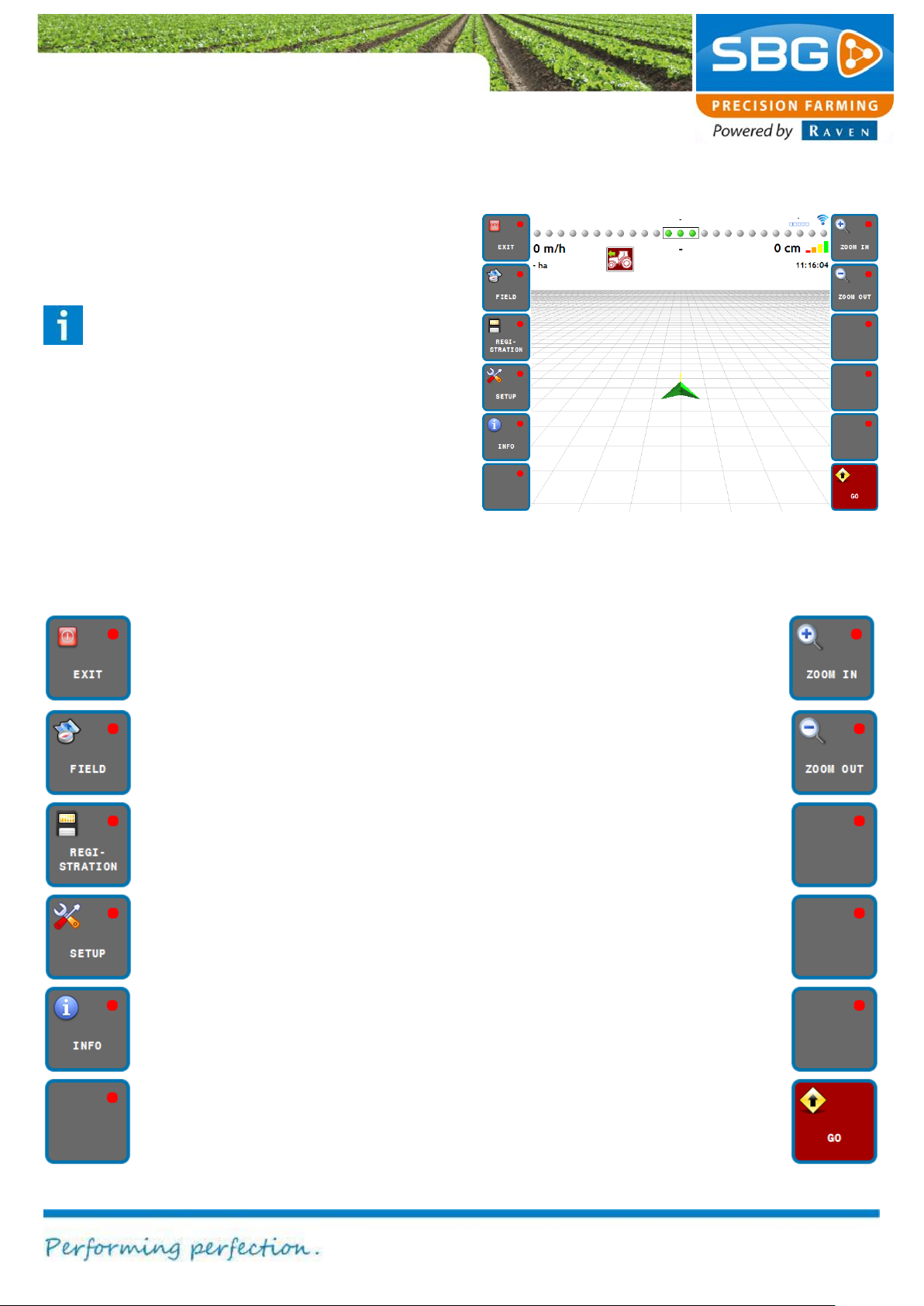
Terminating the software Press and
hold exit key for 3 secs. The software
will be terminated and the loader will
be displayed again.
Zoom in (display)
Go to field menu Zoom out (display)
Go to registration menu
Go to settings menu
Go to info menu
Activate/deactivate autosteer
Figure 17 SBGuidance main menu
3. Main menu
The main menu of SBGuidance (Figure 17) is
displayed after tapping on SBGUIDANCE in the
loader screen.
Please note!
The tractor must always be stationary
when the software is initialised. The
electronic terrain compensation module
will now be initialised.
3.1. Soft-keys
Below is an overview of the keys available in
the main menu (soft-keys).
Page 20
Main menu
Page 20/70 | May 2015 | 2.0
no GPS signal
GPS signal without corrections
GPS signal + EGNOS
RTK-Float
RTK-Fix
1
2
3 4 5
6 7 8
9
10
11
12
13
14
Figure 18 Status information SBGuidance main screen
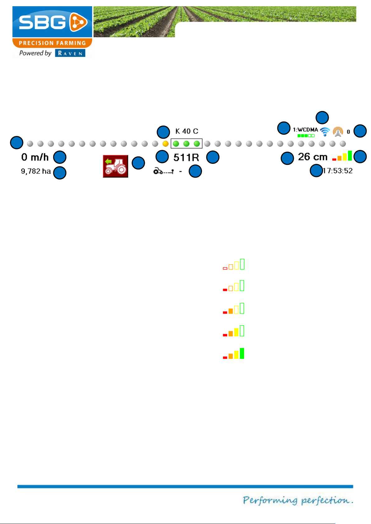
3.2. Information in the top menu bar
General information can be found in the top
menu bar (Figure 18). This information is
displayed continuously to the user, regardless
of the menu that is selected.
1. Name of the selected field
2. Signal strength of GeoConnect 3G: if
a correction signal is used on a GSM
network, the signal strengths and GSM
connection types are displayed here:
yellow/orange boxes = 2G connection;
green = 3G connection. If a Slingshot
modem is used the signal strength and
connection type cannot be seen on the
terminal and this information is only
available on the Slingshot portal.
3. Internet connection:
Blue symbol = internet access
Grey symbol = no internet access
4. Diff. Age: age of the last correction
message (seconds).
5. LED indicator bar: displays the position
with respect to the reference lines. The
scale of the LED’s can be changed by
touching the LED strip.
6. Speed
7. Operating surface: this surface area is
linked to the loaded field.
8. Display forwards/backwards: if the
driving direction displayed deviates from
the actual driving direction, this can be
changed by tapping on the symbol.
9. Number of tracks
10. Distance to headland line
11. Deviation from reference line
12. Indication of GPS signal strength:
13. GPS time
14. Status of crop registration: if the crop
registration is activated a diskette symbol
will blink at position 13. A pause symbol
will blink when the crop registration is
interrupted. If no crop registration is
used, this position is blank.
Page 21
Settings
Page 21/70 May 2015 I 2.0
Display/change
current operation.
Load existing
operations.
Define a new
operation
Figure 19 Field menu
Switch between
operations
Figure 20 Options for creating a new field
4. Fields
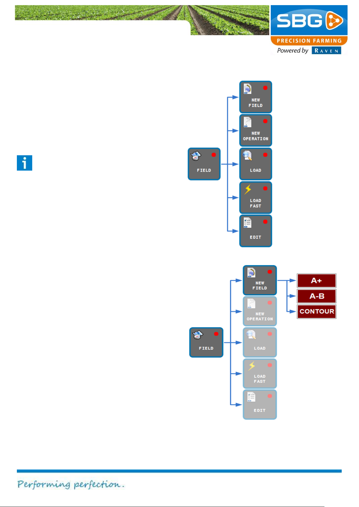
Figure 19 shows which functions are invoked after
activating the FIELD key.
Each application can be aborted at any time by
tapping on ABORT at the top left of the screen.
The main menu can be reached again by tapping
on BACK at the top left of the screen.
Please note!
When ABORT is tapped, all data already
entered is lost, as well as all defined points
and reference lines. This is why the user is
always asked to confirm the use of this key.
4.1. Creating a new field
A field consists of one or more straight and/or
curved field boundaries, or a complete contour.
Each field boundary has a starting point and a
destination point (end point). Corner points must
be set for all types of field.
Create a new
field.
fields and
Creating a new field: Tap on FIELD in the main
menu and then on NEW FIELD. Three different
options for defining the field will now be displayed
on the screen. A schematic representation is
shown in Figure 20.
Page 22
Settings
Page 22/70 | May 2015 | 2.0
Figure 21 Creating a field: A+
Figure 22 Setting the direction
4.1.1. A+ field
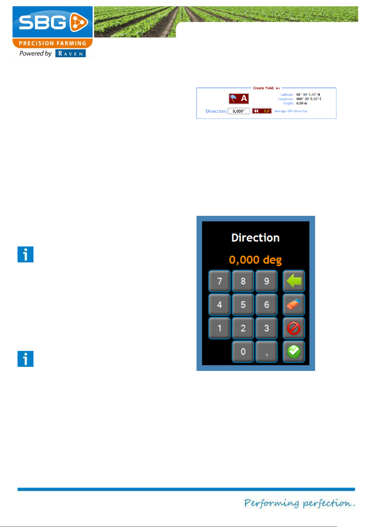
When defining a field in this way, a reference line
is created based on a fixed point. A prerequisite
for defining a field in this way is that the direction
of the required reference line is already known.
After tapping A+ at the bottom of the screen, the
menu will display the option Create field: A+
(Figure 21).
Now set your vehicle in the correct position. The
front of the vehicle should be pointing towards the
end of the field. Tap on A at the bottom of the
screen in order to define the starting point of the
reference line. The A coordinate is now saved.
This can be derived from the numbers behind the
latitude, longitude and height.
Tip!
When defining the A point, the vehicle must
be stationary. This makes it easier to
precisely define where this point should be.
Point A is the position of the GPS antenna
on the tractor.
The numbers under A+ are used to define the
direction (Figure 22). This value can be set to a
value between 0.000 and 360.000 degrees.
Tip!
In order to ensure the highest degree of
accuracy, the direction must always be
given with three decimal places.
In addition to the manual entry of the direction,
you can also drive a few metres so that a value
will appear in Average GPS direction. The value
can now be entered automatically in Direction.
The defined field can now be saved by tapping on
READY at the top left of the screen. This
operation can be aborted by tapping on ABORT.
Page 23
Settings
Page 23/70 May 2015 I 2.0
You will then be asked if you wish to save the
field. If you tap on YES, you can then name the
field so that the field defined in this way is easier
to find in the list of fields. If you tap on NO, the
field will be saved with the name TEMPORARY
FIELD. The temporary field will be lost if you
choose to create a new field and do not save the
temporary field.
After the save operation described above has
ended, an option is displayed at the bottom of the
screen to create a new field or new operation.
To “Create a new field”, see chapter 4.1.
To “Define a new operation”, see chapter 4.2.
Page 24
Settings
Page 24/70 | May 2015 | 2.0
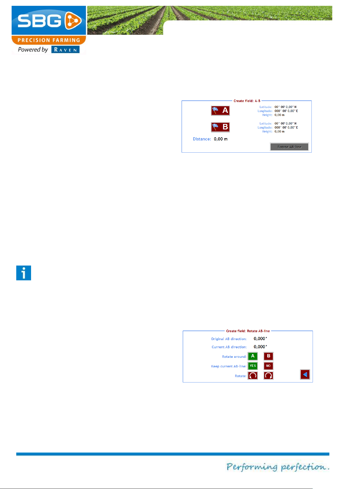
Figure 23 Create field: A-B
Figure 24 Rotating the AB line
4.1.2. A-B field
In this type of field, a reference line is created
between two fixed points.
After tapping AB at the bottom of the screen, the
menu will display the option Create field: A-B
(Figure 23).
Define point A by placing yourself in the position
where the reference line has to start, and then tap
on A. Now move to the end of the field and tap B.
SBGuidance will automatically draw a straight line
between these two points. The distance between
point A and B is displayed at the bottom of the
screen. This distance must be at least 20 metres.
As long as the field has not been saved, it is
always possible to define one of the two points
again. In order to ensure that the AB line runs
parallel to the edge of the field, it is important that
point A and point B have the same distance to the
edge of the field.
Tip!
When defining point A, the vehicle must be
stationary. This makes it easier to precisely
define where this point should be. The
corner point is the position of the GPS
antenna on the tractor.
[Optional step]
After points have been set, it is possible to add a
headland line using Rotate AB line (Figure 24).
Select the point from which the headland turn
should be made and then tap the icon with the
direction in which to turn. Then add the desired
angle for the headland turn.
It is always possible to return to the previous
menu using the blue arrow at the bottom right of
the screen.
Page 25
Settings
Page 25/70 May 2015 I 2.0
The defined field can now be saved by tapping on
READY at the top left of the screen. This
operation can be aborted by tapping on ABORT.
You will then be asked if you wish to save the
field. If you tap on YES, you can name the field so
that the field defined in this way is easier to find in
the list of fields. If you tap on NO, the field will be
saved with the name TEMPORARY FIELD. The
temporary field will be lost if you choose to create
a new field and do not save the temporary field.
After the save operation, described above, has
ended, an option is displayed at the bottom of the
screen to create a new field or new operation.
To “Create a new field”, see chapter 4.1.
To “Define a new operation”, see chapter 4.2.
Page 26
Settings
Page 26/70 | May 2015 | 2.0
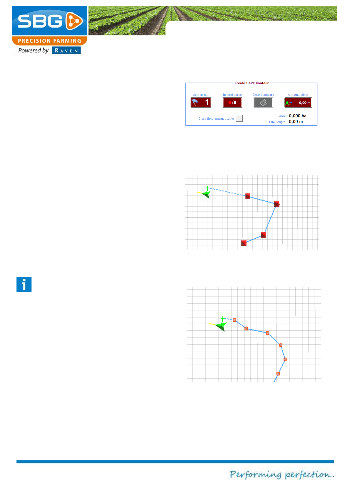
Figure 25 Create a field: Contour
Figure 26 Example of a corner point
Figure 27 Example of recording a corner point
4.1.3. Contour field
Creating a field in this way allows an entire
contour of a field to be defined, or even only one
side with a curved section.
After tapping on CONTOUR at the bottom of the
screen, the menu will display the option Create
field: Contour screen (Figure 25).
First enter the distance of the GPS antenna from
the field boundary in Antenna Offset. The minus
symbol (-) can be used to position the offset to the
left or to the right. In Figure 26, the green arrow
indicates the vehicle (GPS antenna) and the green
cross indicates the position of the field boundary.
Defining a corner point:
Define the first corner point of the desired starting
position of your vehicle by tapping on Add corner
point. Corner point 1 is now defined. This step
must be repeated for a field that only has straight
boundaries until all corner points are defined.
Tip!
Quite often, it is very difficult to position the
vehicle precisely in the corner of a field.
Therefore, always define two corner points
in each corner! Corner points defined
further away from and outside the corner
ensure that the direction of the boundaries
can also be more accurately defined.
Recording a curve:
A curve can be recorded in order to define a
curved reference line. Place the vehicle in the
desired starting position and then tap on Record
Curve. The recording symbol will now turn green.
Now drive precisely parallel to the curved side in
order to ensure an accurate recording.
Page 27
Settings
Page 27/70 May 2015 I 2.0
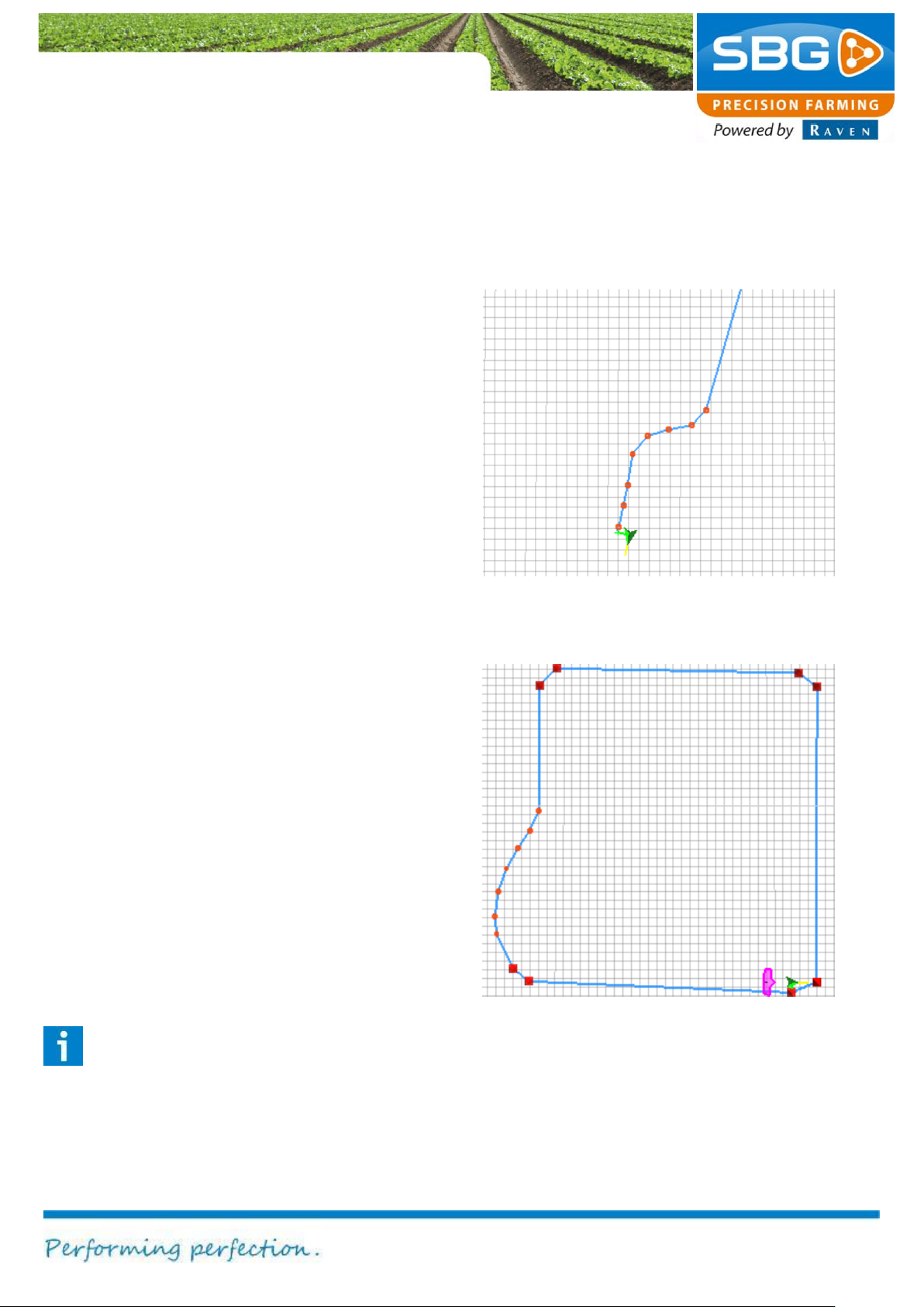
Figure 28 Example of recording a combination of a
curved and straight line section
Figure 29 Example of a field
When recording a curve, if a corner of the field or
the end of the reference line is reached, tap on
Add corner. SBGuidance will now apply a corner
point to the last position (red pyramid on the
screen).
It is possible to alternately define straight and
curved line segments of a field by activating or
deactivating the Record Curve key.
If a curved section has to be joined with a straight
section on the same boundary line, tap on Record
Curve at the transition between the straight and
curved sections. You will then be asked: “Is this
point a corner point?” If the straight line section
is to be joined to the curved line section, the
response to this question should be No. This
enables a curved and straight line section of an
existing field boundary to be used as a reference
line. If the response to this question is YES, a
corner point will be created. The curved and
straight line sections are then defined as two
different sides of the field.
Now tap on Close field in order to draw a straight
reference line from the last corner point to the first
corner point. The surface area within the defined
contour will then be calculated after closing the
field. If you have only entered a single curved
side, you do not need to close the field.
If Close field automatically is selected,
SBGuidance closes the field automatically when
the vehicle is within a radius of 5 metres from the
first corner point.
Please note!
A corner point separates two different sides
of a field. Do not add a corner point to the
centre of a side that is considered as a
whole.
Page 28
Settings
Page 28/70 | May 2015 | 2.0
The defined field can now be saved by tapping on
READY at the top left of the screen. This
operation can be aborted by tapping on ABORT.
You will then be asked if you wish to save the
field. If you tap on YES, you can name the field so
that the field defined in this way is easier to find in
the list of fields. If you tap on NO, the field will be
saved with the name TEMPORARY FIELD. The
temporary field will be lost if you choose to create
a new field and do not save the temporary field.
After the save operation described above has
ended, an option is displayed at the bottom of the
screen to create a new field or new operation.
To “Create a new field”, see chapter 4.1.
To “Define a new operation”, see chapter 4.2.
Page 29
Settings
Page 29/70 May 2015 I 2.0
Figure 31 Defining a new operation
Figure 30 Defining a new operation
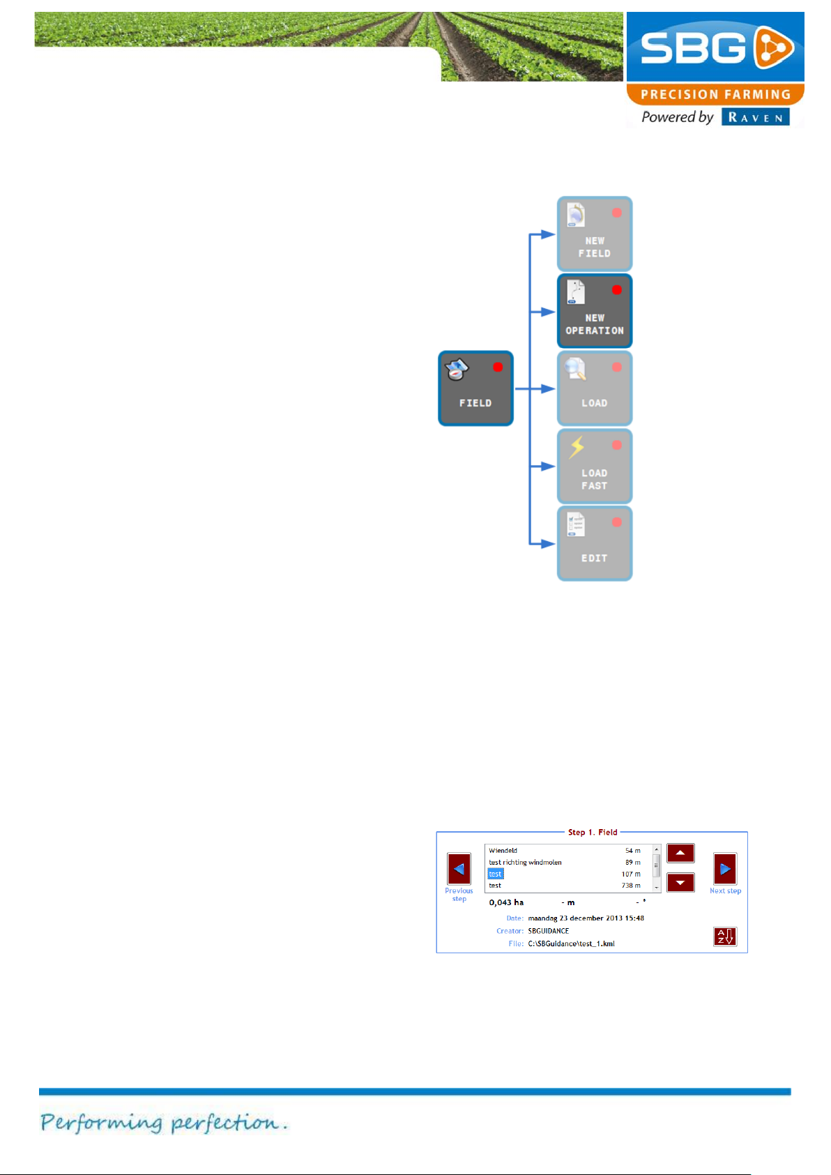
4.2. Defining a new operation
In order to perform an operation on a field that has
been created, an operation must first be defined in
SBGuidance. Operations are always linked to a
particular field. Therefore, at least one operation
must be defined for each individual field in order to
use a field in SBGuidance.
Figure 30 shows which keys should be tapped to
add a new operation. In addition, SBGuidance
proposes a new operation after a new field is
saved.
After tapping NEW OPERATION, the Operation
menu will be displayed at the bottom of the screen
(Figure 31).
This menu presents a summary of the five steps
required to define an operation:
1. Select the desired field.
2. Select the desired reference line.
3. Define the machine width.
4. Define the operation offset.
5. Define the headland turning point
(optional).
Select the field on which the operation has to be
performed (Figure 31). The selection is highlighted
in blue.
Furthermore, detailed information concerning the
selected field is displayed at the bottom of the
screen. The distance between the current position
and the field is displayed to the right of the field
name.
The alphabetical order of the list can be changed
by tapping on A-Z at the bottom right of the
screen. The options window enables operations to
be sorted by date, name or distance.
Page 30
Settings
Page 30/70 | May 2015 | 2.0
Figure 32 Defining an operation - step 2
Figure 33 Defining an operation - step 3
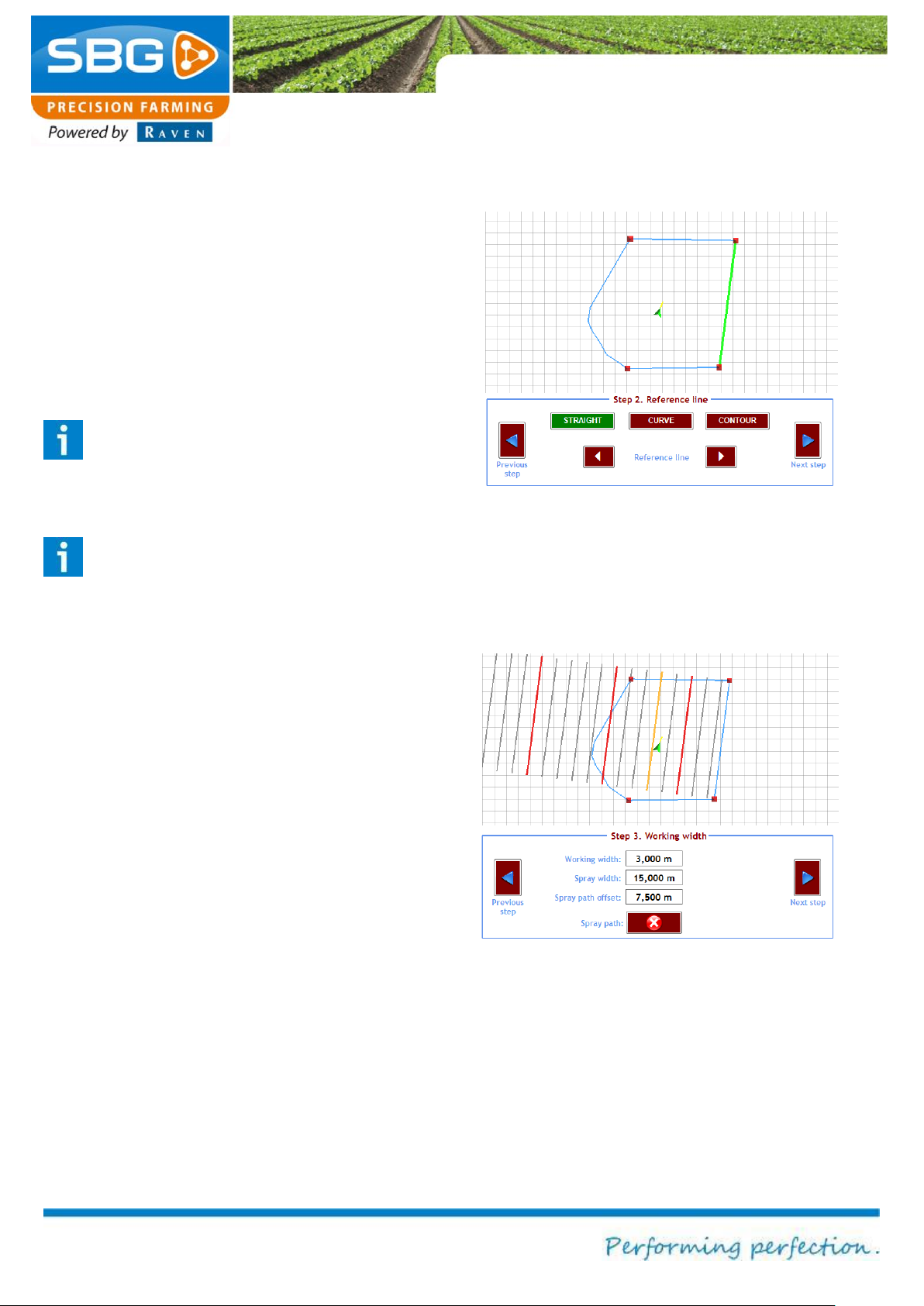
Tap on Next step.
Select the reference line (field boundary) parallel
to which the operation has to be performed.
Select the desired drive mode (straight, curved or
contour) and use the arrows to the left and right of
the word Reference line to select the desired
reference line. The selected reference side is
highlighted green (Figure 32).
Please note!
Straight lines shorter than 20 metres in
length cannot be selected for defining an
operation.
Please note!
If two straight lines at the opposite sides of
the field run more or less parallel, only one
of the two lines can be selected for defining
an operation.
Tap on Next step. If desired, change the
operating width of the operation. If necessary,
also change the spraying width.
The input field Spraying path offset is used to
enter the distance between the defined field
boundary and the first spraying track. This is
normally half the spraying width (for a spraying
width of 15 metres, i.e. 7.5 metres).
Page 31
Settings
Page 31/70 May 2015 I 2.0
Figure 35 Defining an operation - step 4
Figure 34 Defining an operation - step 3
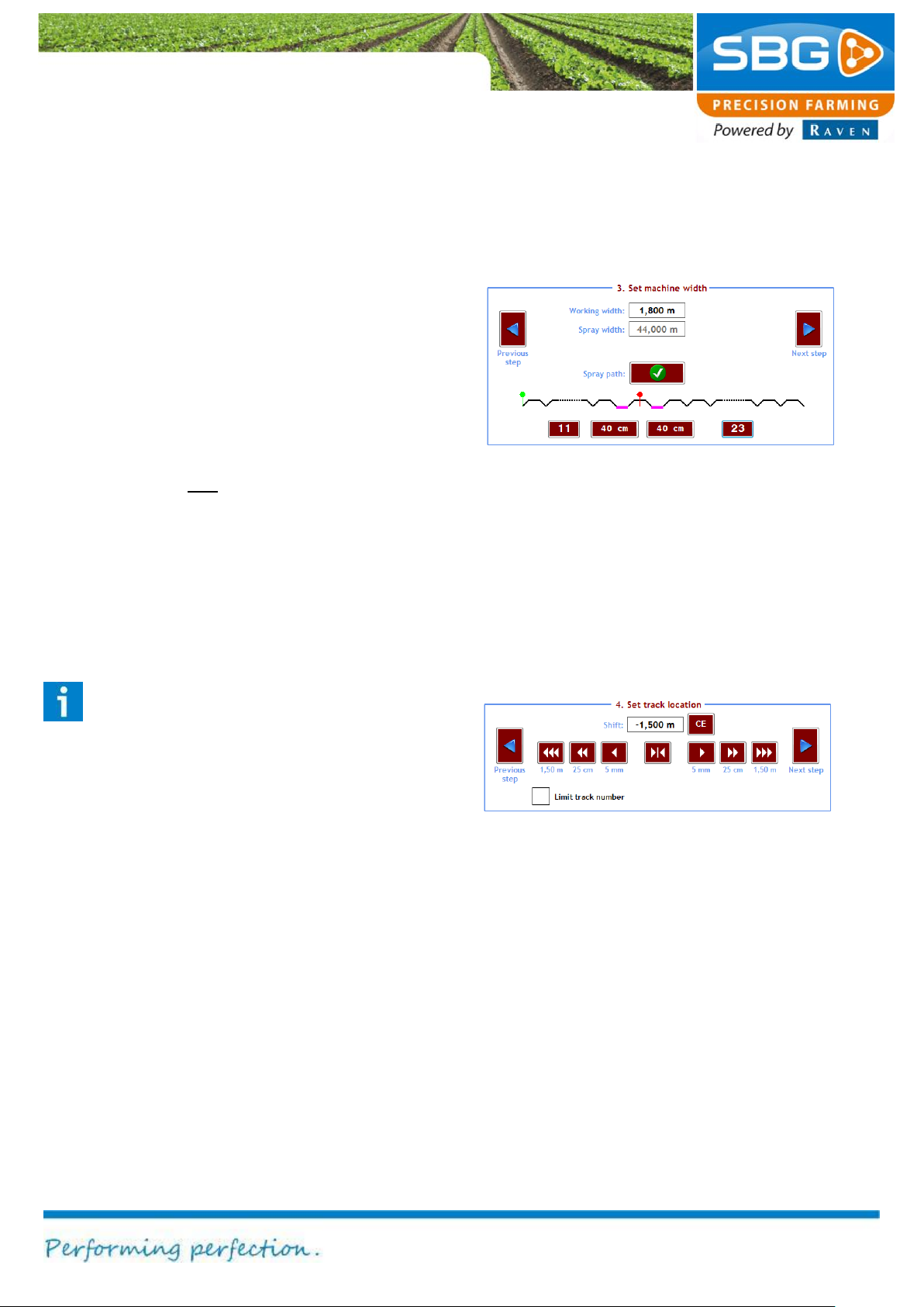
When performing operations on spraying paths
with varying spraying widths, the position of the
spraying path can be defined using the Spraying
path key (Figure 34).
The number of machine operations is indicated on
the basis of the spraying width entered. The figure
shows the operations in the form of beds. The
green marking on the left shows the field boundary
and the red marking shows the position of the first
spraying path.
The left key is used to define the number of
operations of the first spray track. The right key
indicates the number of tracks between all
subsequent spraying operations.
The additional space to the left and/or to the right
of the spraying operation is entered using the two
centre keys. Entering a negative value reduces
the spraying width.
Tip!
A spraying track at a different location (e.g.
due to an obstacle) is best achieved by
using the manual mark spray track function.
See for more information section 4.5.
Tap on Next step.
Shift the operations to the correct position (Figure
35). On a contour field the displacement defaults
to half the working width. On an AB field the
displacement is 0 metres by default (i.e. the AB
line lies precisely beneath the tractor).
By selecting Limit track number, the user can
limit the number of visible and usable tracks in the
screen.
Page 32
Settings
Page 32/70 | May 2015 | 2.0
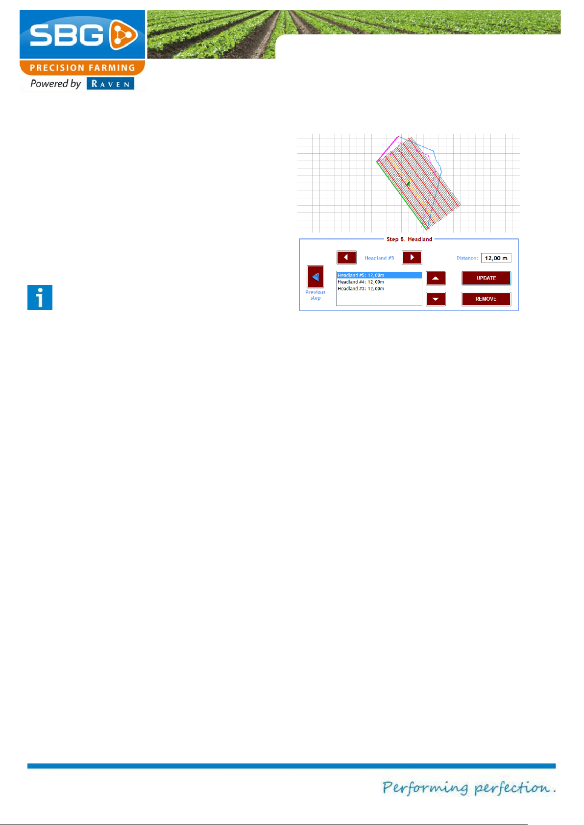
Figure 36 Defining an operation - step 5
Tap on Next step.
Define the headland line(s). The white arrows on
the left and right of the word Headland #X can be
used to select the desired field sides. The
selected side is marked in violet. The defined
distance is allocated by selecting Update. A
different distance can be defined for each
individual headland turn. It is always possible to
change the headland distances again after they
have been defined.
Tip!
Place a minus sign (-) before the distance
to position the headland line on the other
side of the field boundary.
The operation is now defined.
Tap on READY at the top left of the screen to
save the operation, or on BACK to cancel the
operation.
A message will then be displayed. Selecting YES
enables the operation to be named. If NO is
selected, the operation is loaded but not saved.
The operation is lost as soon as another field is
selected.
Page 33
Settings
Page 33/70 May 2015 I 2.0
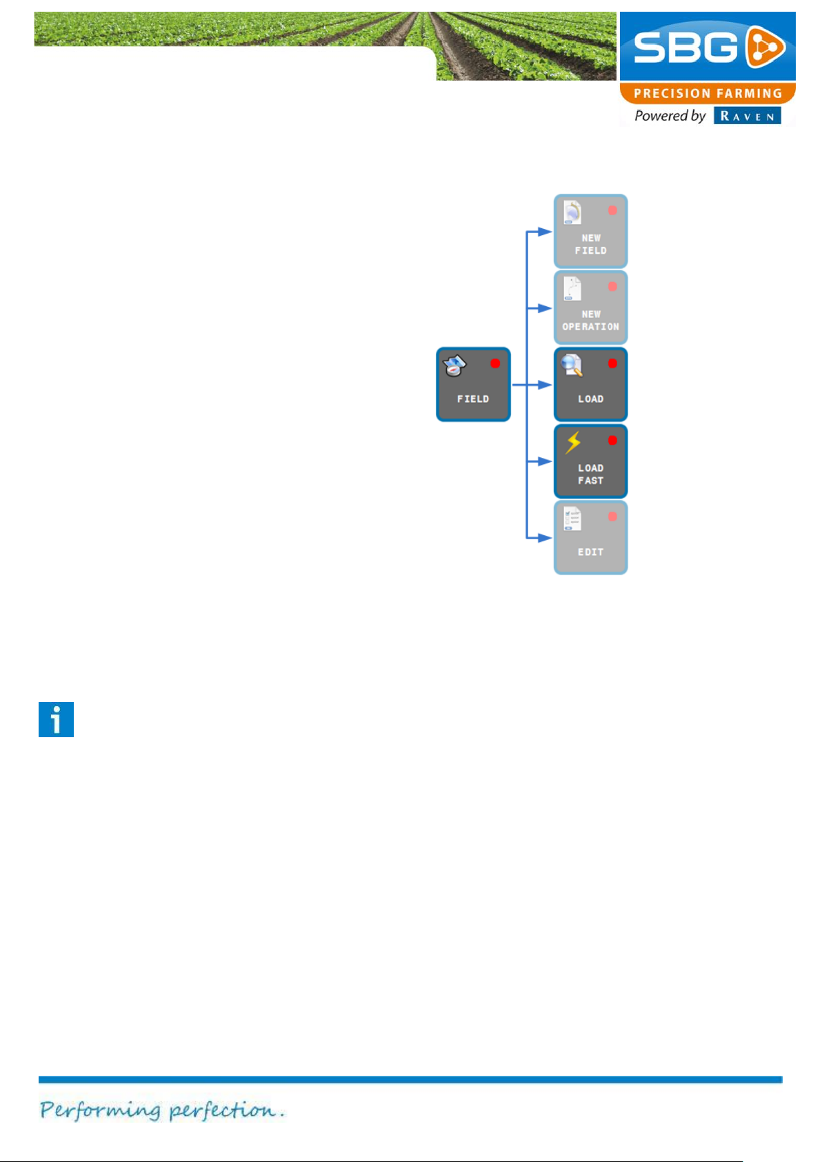
Figure 37 Loading fields
4.3. Loading fields
Select FIELD and then LOAD (Figure 37).
Select the desired field.
Tap on Next step and then select the desired
operation.
Confirm the selection by tapping on READY at the
top left of the screen.
The selected fields and operation will now be
loaded.
4.4. Load fast
After loading a field it is possible to switch fast
between saved operations. Tap on FIELD, then on
LOAD FAST. Thereafter, the OPERATION menu
will be visible.
Tap on the arrows in the menu to switch between
the different saved operations under the loaded
field. It is even possible to activate the auto
steering (GO) from this menu.
Tip!
Use this function to switch quickly between
the different operations while working on
the headlands.
Page 34
Settings
Page 34/70 | May 2015 | 2.0
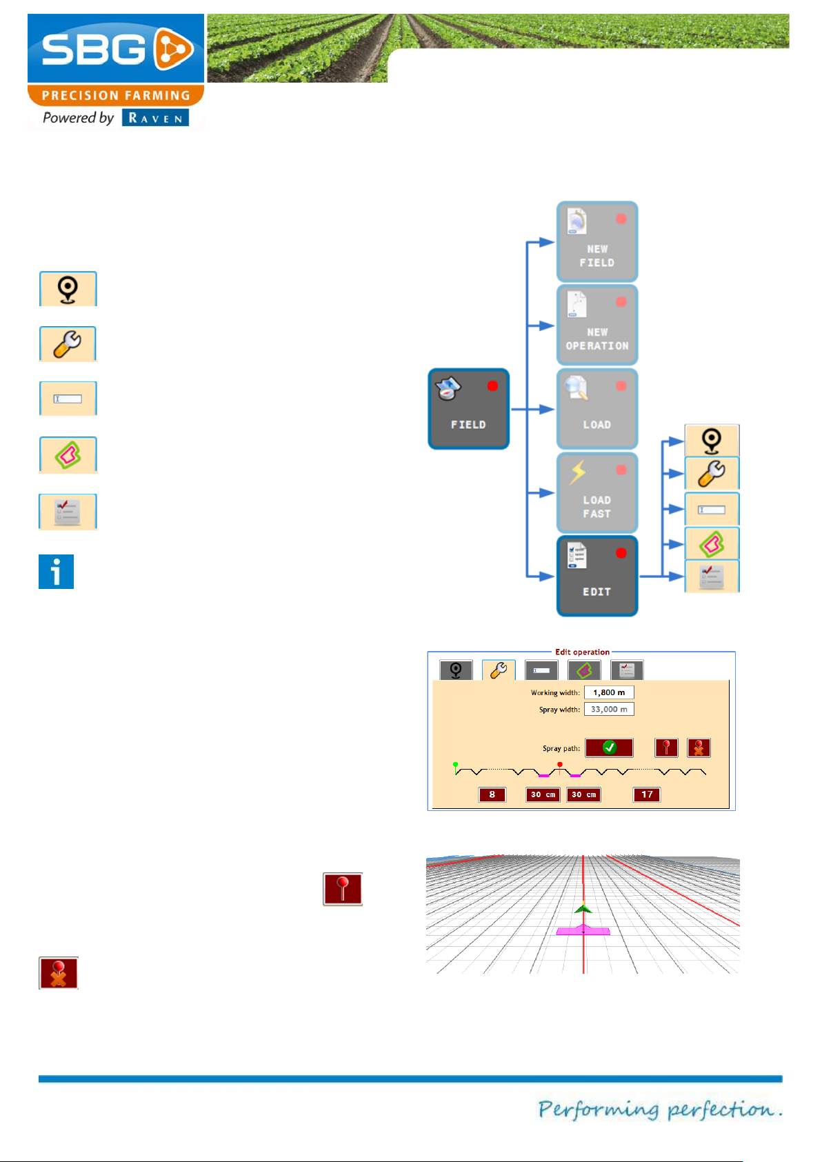
Figure 38 Editing an operation
Figure 39 Menu to mark track as spray track
Figure 40 Marked spray track
4.5. Edit fields
Tap on FIELD and then on EDIT (Figure 38). The
Edit operation menu will now be displayed.
The edit menu contains of five tabs:
Location and shift
Working width and spray tracks
Field name
Headland
Lock operation
Please note!:
The lock operation function is irreversible.
So, if this function is activated, it is not
possible to change anything back on the
operation.
In the tab working width and spray tracks the
normal working width and spray working width can
be edited (Figure 39). Besides that it is possible to
manually mark a track as a spray track, which
allows the user to mark a spray track on a random
place in the spray track pattern. After this manual
marked spray track the original spray track pattern
continues (Figure 40). It is possible to mark
several spray tracks manually with the
button. If the manual marked spray track is the
nearest track, this line can be removed with the
button.
Page 35

Settings
Page 35/70 May 2015 I 2.0
Changing the CAN
module settings.
Changing the
Changing the
Changing the GPS
settings.
Changing vehicle
and tuning.
Figure 41 Settings menu
Figure 42 Settings vehicle
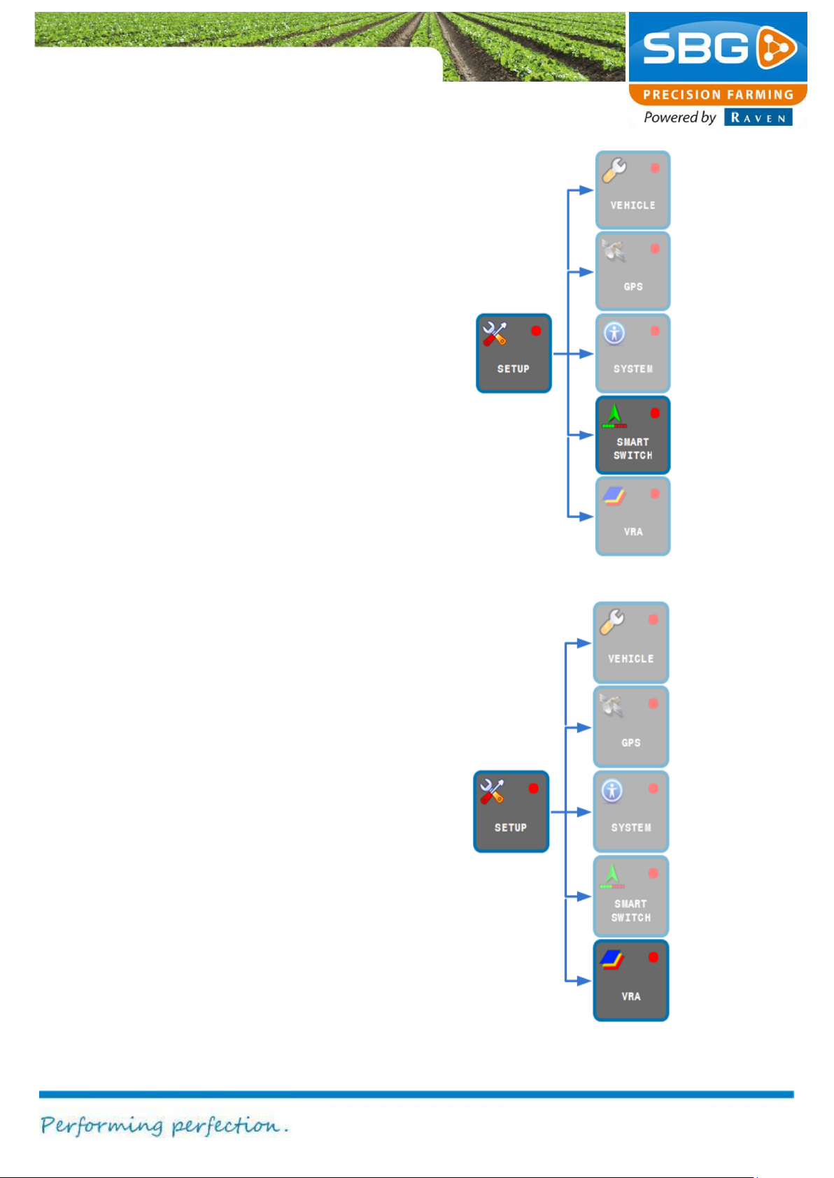
5. Settings
Figure 41 shows which functions are invoked after
selecting the SETUP key.
The main menu can be reached again by tapping
on BACK at the top left of the screen.
5.1. Vehicle settings
Press the VEHICLE key. The options TUNING
and OFFSETS (top right) are used to change the
vehicle settings (Figure 42).
As a default, the TUNING window is displayed at
the bottom of the screen. This window can be
used to change the parameters for the steering
system of the tractor and/or implement. The
different steering systems will be discussed in the
following sections in more detail.
settings like
machine offsets
and modem
display and
language.
settings for
variable metering.
Tip!
The correct tuning parameters will depend
on the field conditions and the operation to
be performed.
Please note!
Changes made to the tuning of the machine
may result in incorrect steering of the
machine. Therefore, always write down the
initial value on paper, before making any
changes.
Page 36
Settings
Page 36/70 | May 2015 | 2.0
Standard
Range
Hydraulics
100 %
50 - 150 %
Gain
100 %
50 - 400 %
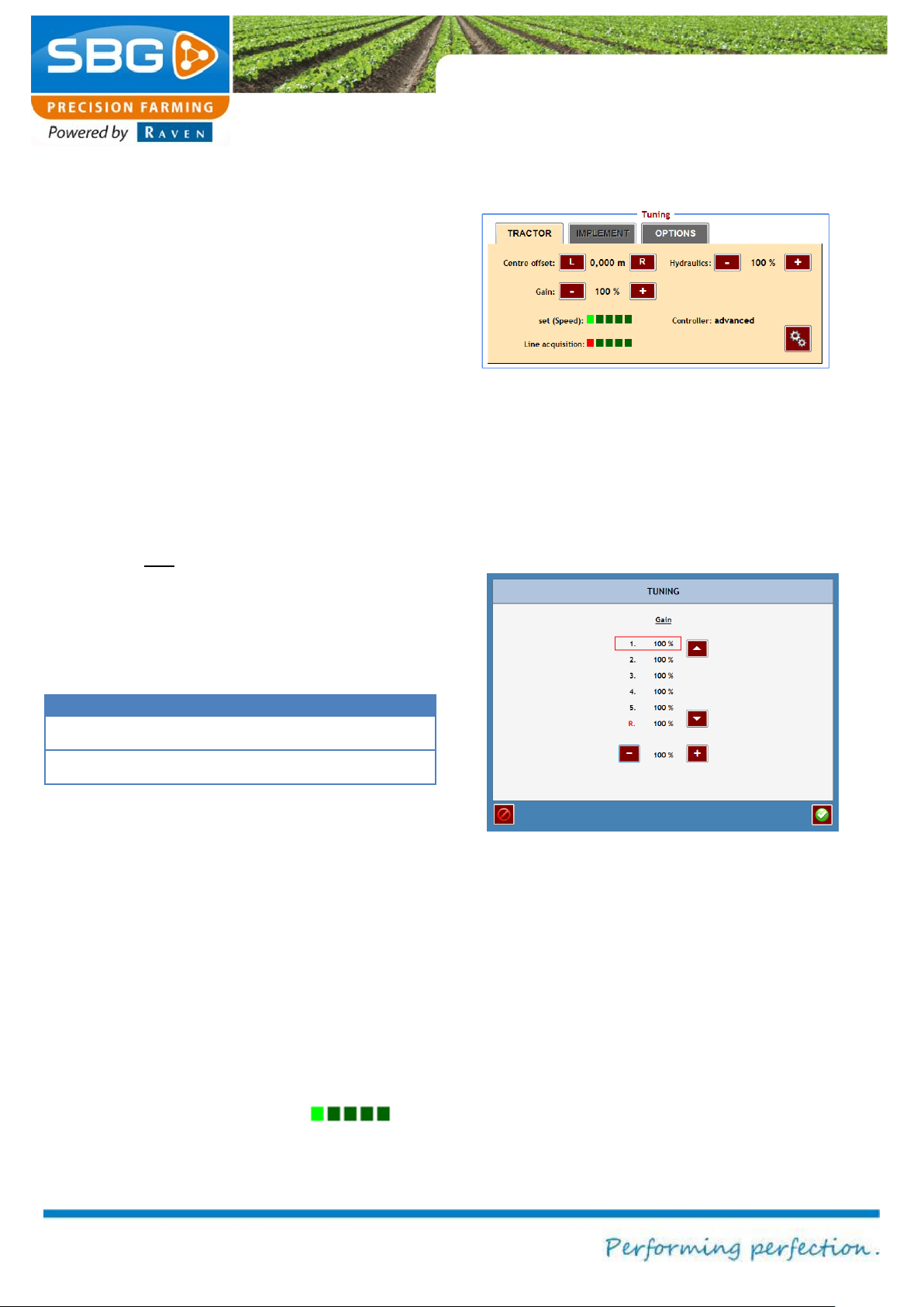
Figure 44 Changing the gain per speed set
Figure 43 Tuning SBGuidance Auto
5.1.1. SBGuidance Auto
Tuning
When only tractor steering (no implement
steering) is set by the dealer in the SBGuidance
Configurator tool, only the TRACTOR tab is active
in the user software (Figure 43).
If the centre offset is changed, the centre position
of the tractor is shifted. This will change the
connection distance between the operating tracks.
The left connection distance to the following track
becomes narrower if L is tapped and wider if R is
tapped.
Example: For a defined connection on the left of
71 cm instead of 75 cm, the centre offset must be
adjusted by half the connection distance error. In
this case it would be 4 cm/2 = 2 cm (tap on R).
Hydraulics = Steering response speed
Gain = Sensitivity
If the steering does not react quickly enough, the
hydraulic settings must be increased in
increments of 5% until the steering reacts rapidly.
If the vehicle is too slow in steering towards the
line, without overshooting the line, then increase
the gain in increments of 20% until the steering
becomes too aggressive. Once the steering has
become too aggressive, reduce the gain by 20%.
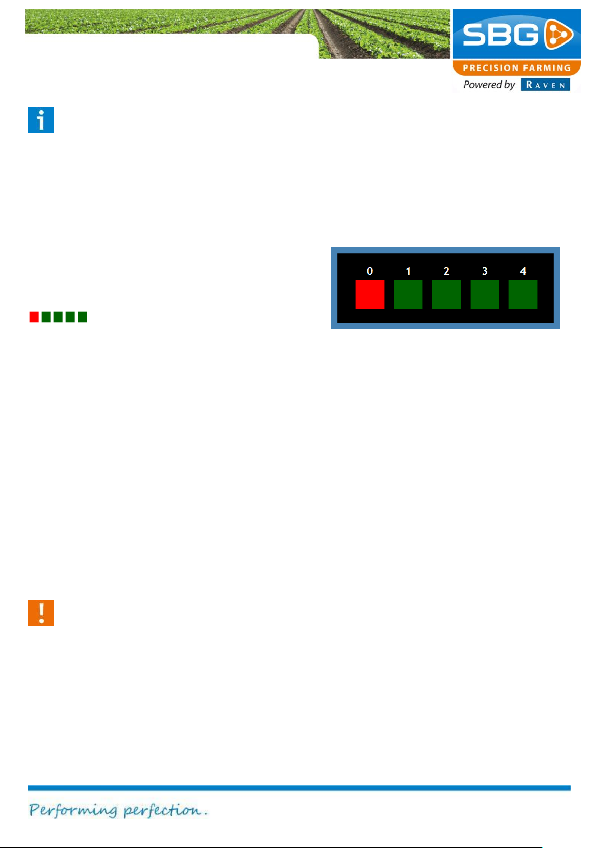
The gain can be adjusted separately for 5 different
speed ranges. The Set (speed) indicator displays
the active driving speed by means of a bright
green box. Tap on the indicator to open
the input menu (Figure 44Figure 44). The increase
of each range can now be changed when the
vehicle is stationary.
Page 37
Settings
Page 37/70 May 2015 I 2.0
Figure 45 Line acquisition
Please note!
If the steering system alternates
continuously between two speed ranges,
the steering may not always indicate the
desired driving behaviour. Drive faster or
slower so that only one speed set remains
active or make sure that the gain values in
the two speed sets are equal.
With Line acquisition you can chose how quickly
the tractor steers towards the line. This is
particularly important when auto steer is activated
while driving far from the active track. Tap on the
indicator, to open the line acquisition
settings screen (Figure 45) and chose the desired
value.
Value 0: machine steers aggressive towards the
active track (for example: to steer quickly on the
line while leaving the headland).
Value 4: machine steers lazy towards the active
track (for example: while using a self-propelled
sprayer).
Controller indicates the type of controller:
Advanced (standard controller)
With Calibration several parameters of the
steering system can be changed, like wheel
sensor voltages, minimal steering voltages and
pressure sensor value.
Warning!:
The hydraulic, gain and line acquisition
parameters are already set by the dealer
during the installation and calibration of the
steering system. Changing these
parameters can cause poor performance of
the steering system. Therefore, please
contact your SBG dealer before changing
these parameters.
Page 38
Settings
Page 38/70 | May 2015 | 2.0
Figure 46 Defining offsets
Figure 47 Machine offsets tractor
Figure 48 Machine offsets rear implement
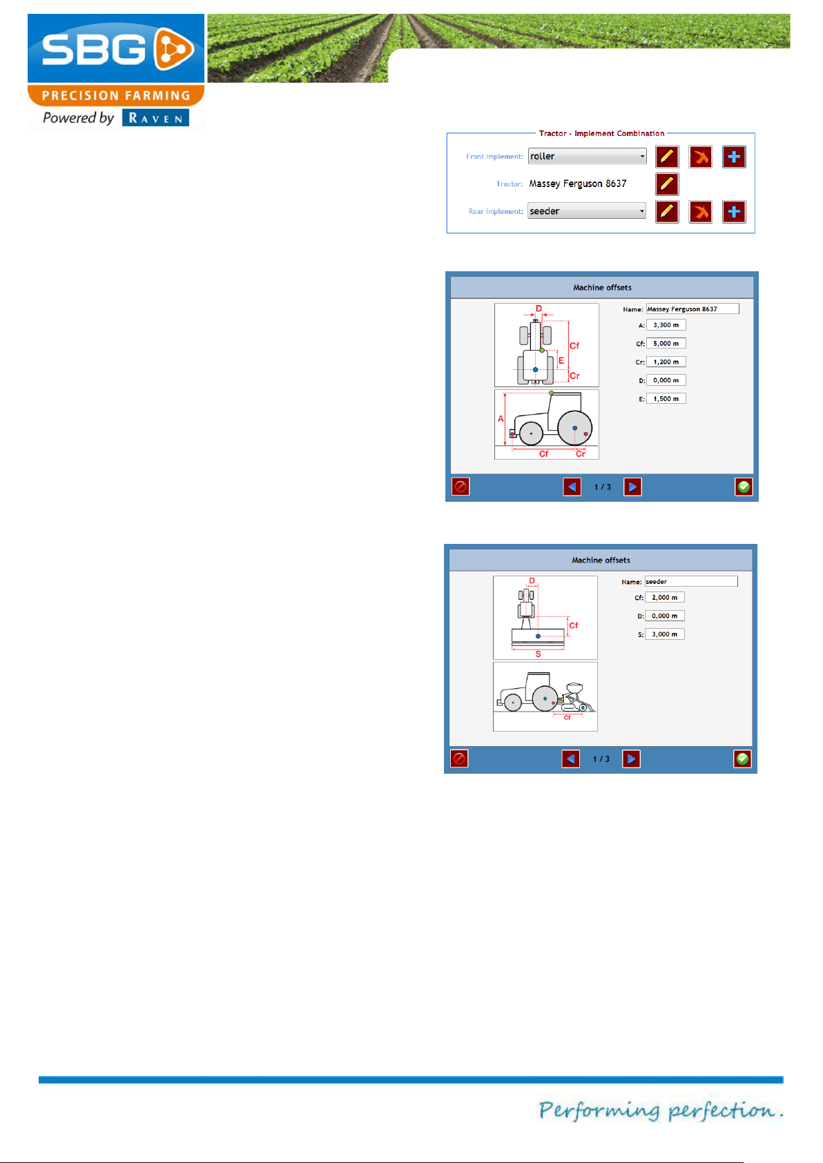
Offsets
Tap on VEHICLE and then on OFFSETS (top
right).
The offsets menu will now be displayed (Figure
46). The OFFSETS option can be used to input all
dimensions of the main vehicle (tractor) and any
front or rear-mounted implements.
Tap on the plus symbol in order to add a new front
or rear-mounted implement.
Tap on the red X symbol in order to delete the
selected implement.
To open the Offsets menu of a tractor and front or
rear-mounted implements, tap on the pencil.
Input the dimensions and the name of the tractor
in the Machine Offsets menu (Figure 47 - Figure
49).
Page 39
Settings
Page 39/70 May 2015 I 2.0
Figure 50 Headland signal
Figure 49 Machine offsets front implement
Figure 51 Offset info
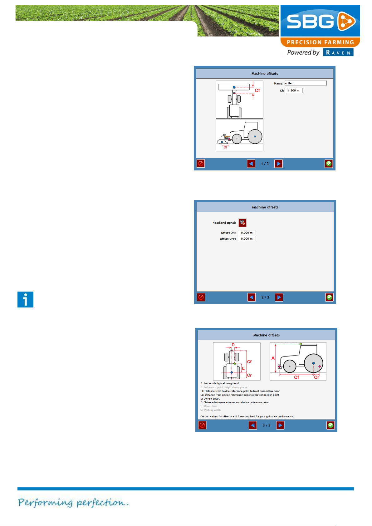
Tap on the blue arrows to navigate to the next
step (Figure 50).
A headland alarm signal for rear and front
implements can be switched on or off. The
headland signal emanates from the reference
point of the machine (blue dot on the drawing).
Tap on the speaker icon at Headland signal to
activate or deactivate the headland signal.
When a negative value is entered at Offset ON
(Figure 50), the headland signal will be outputted
earlier while driving into the field (leaving the
headland). So, the actual signal is outputted
before the set reference point.
When a negative value is entered at Offset OFF
(Figure 50), the headland signal will be outputted
earlier while driving towards the headland (from
the field). So, the actual signal is outputted after
the set reference point.
Tip!:
By putting too large or too small values for
Offset ON and Offset OFF the potential
delay of the machine can be compensated.
Tap on the blue arrows to navigate to the next
step (Figure 51).
In this last step information for all the used
measurements of tractor and implement are
displayed.
Tap on the green checkmark key to save changes.
Tap on the red “abort” key to close this screen
without saving changes.
Page 40
Settings
Page 40/70 | May 2015 | 2.0
Figure 52 Tuning SBGuidance Sideshift
Figure 53 Sensor calibration
Figure 54 Steering percentages calibration
5.1.2. SBGuidance Side-Shift
SBGuidance Side-Shift works standard with
proportional steering. While using heavier
implements, whereby the GPS-antenna is not
installed above the Side-Shift cylinder there is an
option to use the pulse steering. The choice
between proportional and pulse steering can only
be done by a SBG dealer.
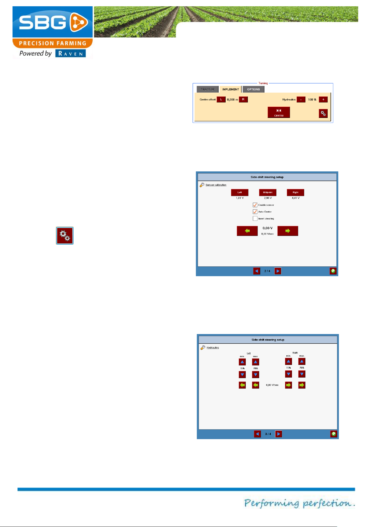
When only side-shift steering is set by the dealer
in the configuration tool, only the IMPLEMENT tab
is active in the user software (Figure 52).
The centre adjustment is the same as in the
tractor steering mode (see chapter 5.1.1).
Tap on the key to open the calibration menu
(Figure 53). In this menu the sensor can be
activated and set. The green arrow keys at the
bottom can be used to manually steer the SideShift cylinder to the left or right. Steer the cylinder
completely to the left and then click on “Left”. The
same applies to the maximum adjustment to the
right and the centre position.
The Auto-Center function steers the Side-Shift
cylinder to the middle position of the cylinder when
the steering is deactivated with the “GO” key in the
main screen. A requirement is that a position
sensor is used on the Side-Shift cylinder.
Check Invert steering when the Side-Shift
cylinder steers in the opposite direction.
Tuning proportional steering
For an optimal steering performance it is important
that the minimal and maximal steering
percentages are set by a SBG dealer (Figure 54).
As a user you can make the steering more or less
aggressive by changing the hydraulic percentage
in the Tuning menu (Figure 52).
Page 41
Settings
Page 41/70 May 2015 I 2.0
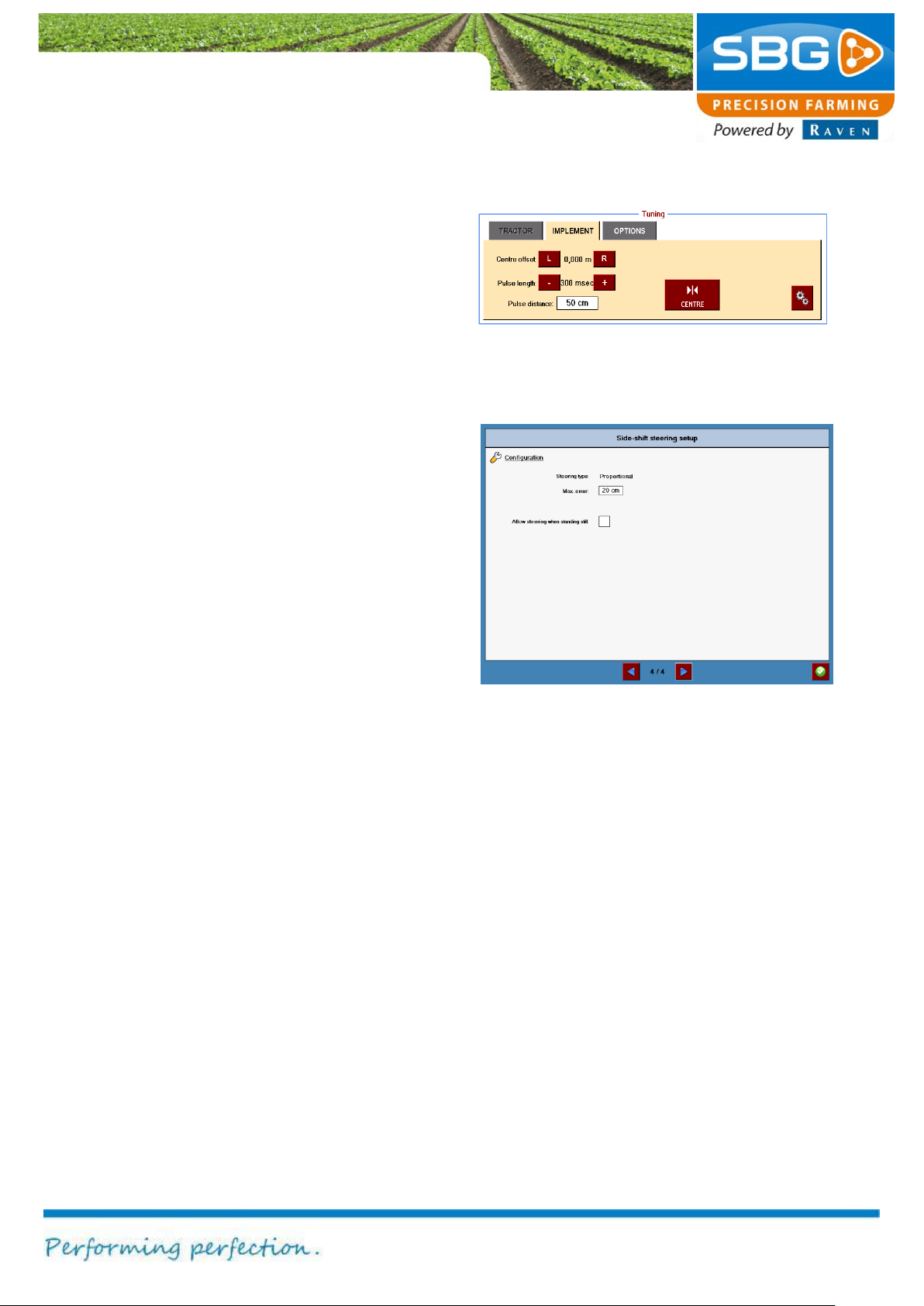
Figure 55 Tuning SBGuidance Sideshift
Figure 56 Configuration settings
Tuning pulse steering
With pulse steering, the Side-Shift cylinder is
steered in small increments (lateral displacement)
and the accuracy of the steering can be changed
in the tuning screen (Figure 55). With Pulse
length the step size of one steer action of the
cylinder is set. The pulse distance is the distance
that must be covered before the next steer action
is performed.
The Side-Shift steering can also be set by altering
the oil flow through the manifold. The pulse length
must be greater if the device drifts and if the
tractor is controlled less straight manually. If the
tractor drives relatively straight by itself and the
device does not drift, a smaller pulse length is
required.
In the last step of the calibration wizard the
steering type (pulse or proportional) is displayed
(Figure 56). Only a SBG dealer can change
between pulse and proportional steering. Besides
that it is possible to set the Max error of the
cylinder. This is the distance range from the
current track wherein the cylinder is allowed to
steer. Outside this range from the current track the
cylinder stops steering.
Offsets
The offsets in SBGuidance Side-Shift are adjusted
in the same way as the offsets in SBGuidance
Auto (see chapter 5.1.1).
Page 42
Settings
Page 42/70 | May 2015 | 2.0
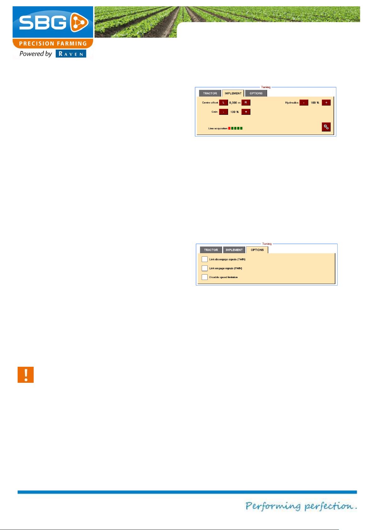
Figure 57 Tuning SBGuidance TWIN
Figure 58 SBGuidance TWIN options
5.1.3. SBGuidance TWIN/Discs
Tuning
All tabs are active when the system is in
SBGuidance TWIN mode (Figure 57).
The tuning of the disc steering is the same as for
the tractor (see chapter 5.1.1).
Tap on the gear-sign (Figure 57) for the additional
settings. Activate Auto Center in these additional
settings to automatically steer the implement to
the centre position if the implement steering is
deactivated. Activate Auto Center (manual
control) to automatically steer the implement to
the centre position if the implement is manually
steered with the left/right keys in the main screen.
The Link disengage signals (TWIN) and the
Link engage signals (TWIN) can be switched on
in the OPTIONS tab (Figure 58). The first option
can be used to switch the implement steering off
at the same time as the tractor steering. The
second option can be used to switch the
implement steering on at the same time as the
tractor steering.
With the Disable speed limitation function the
speed limitation to activate the automatic steering
can be deactivated.
Warning!:
Activate the automatic steering at high
driving speed can cause unexpected
steering behavior and therefore extreme
dangerous situations for man and machine.
Offsets
Offsets are defined in the same way as the offsets
in the SBGuidance Auto mode (see chapter 5.1.1).
Page 43
Settings
Page 43/70 May 2015 I 2.0
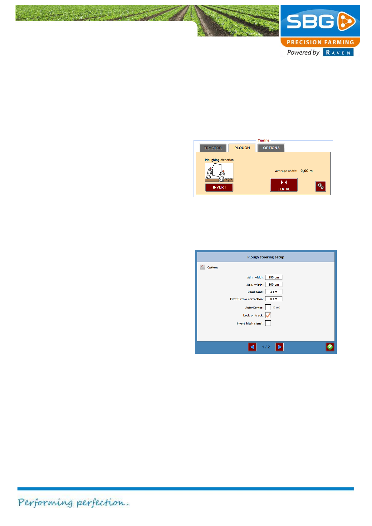
Figure 59 Tuning SBGuidance plough
Figure 60 Plough settings
5.1.4. SBGuidance TWIN/Side-Shift
SBGuidance TWIN with Side-Shift is a
combination of SBGuidance Auto and
SBGuidance Side-Shift steering. A comprehensive
explanation of tuning and how to define offsets is
given in chapters 5.1.1 and 5.1.2.
5.1.5. SBGuidance Vario-plough
Tuning
Figure 59 shows the tuning window for the
SBGuidance Vario-plough.
It is possible to centre the plough with the centre
key. If desired, the ploughing direction can be
changed so that the figure corresponds to the
actual situation.
Tap on the gear-icon to change the remaining
settings of the plough steering (Figure 60).
Restrict the movements of the plough by setting
the Minimum Width and Maximum Width. Give
at the Dead band settings the value for the error
towards the track where the plough can start
steering.
When the error to the track is unequal while
driving back and forth on a line, a centre offset in
the tractor settings can be done. If the error to the
track is equal while driving back and forth a value
can be entered at first furrow correction. The
auto-center function steers the plough cylinder to
a predefined centre position as soon as the
automatic steering is deactivated using the GO
key. If the lock and track function is activated
SBGuidance will steer the plough to the current
active track as long as the steering (“GO” key) is
activated. If this function is not activated
SBGuidance will steer the plough always to the
nearest track.
Page 44
Settings
Page 44/70 | May 2015 | 2.0
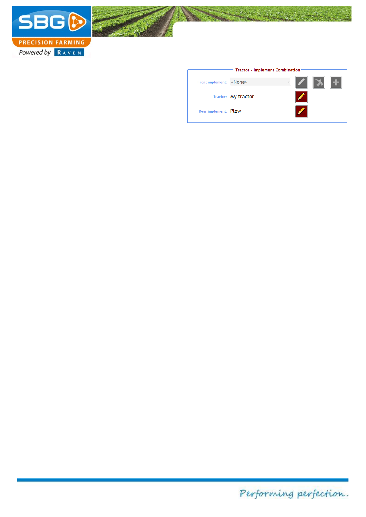
Figure 61 SBGuidance Vario-plough offsets
If a hitch sensor signal of the tractor is used to
automatically activate and deactivate (GO key)
the plough steering system on the headland, it is
possible to invert the signal by checking the
invert hitch signal.
Tap on the blue arrow to the right in the screen to
get more information about the visualized plough
measurements from the main screen.
Offsets
Figure 61 shows the offsets window for the
SBGuidance Vario-plough. Refer to chapter 5.1.1
for defining the offsets of the tractor.
Tap on the pencil symbol next to Plough. The
reference point for the headland signal must be
positioned in the centre of the ploughing width.
Determine on the plough where the reference
point will be and then measure the Cf distance to
the connecting points of the cross-shaft.
Page 45
Settings
Page 45/70 May 2015 I 2.0
Figure 63 Configuring the GPS receiver
Figure 62 GPS set-up
Figure 64 Configuring NMEA1 data
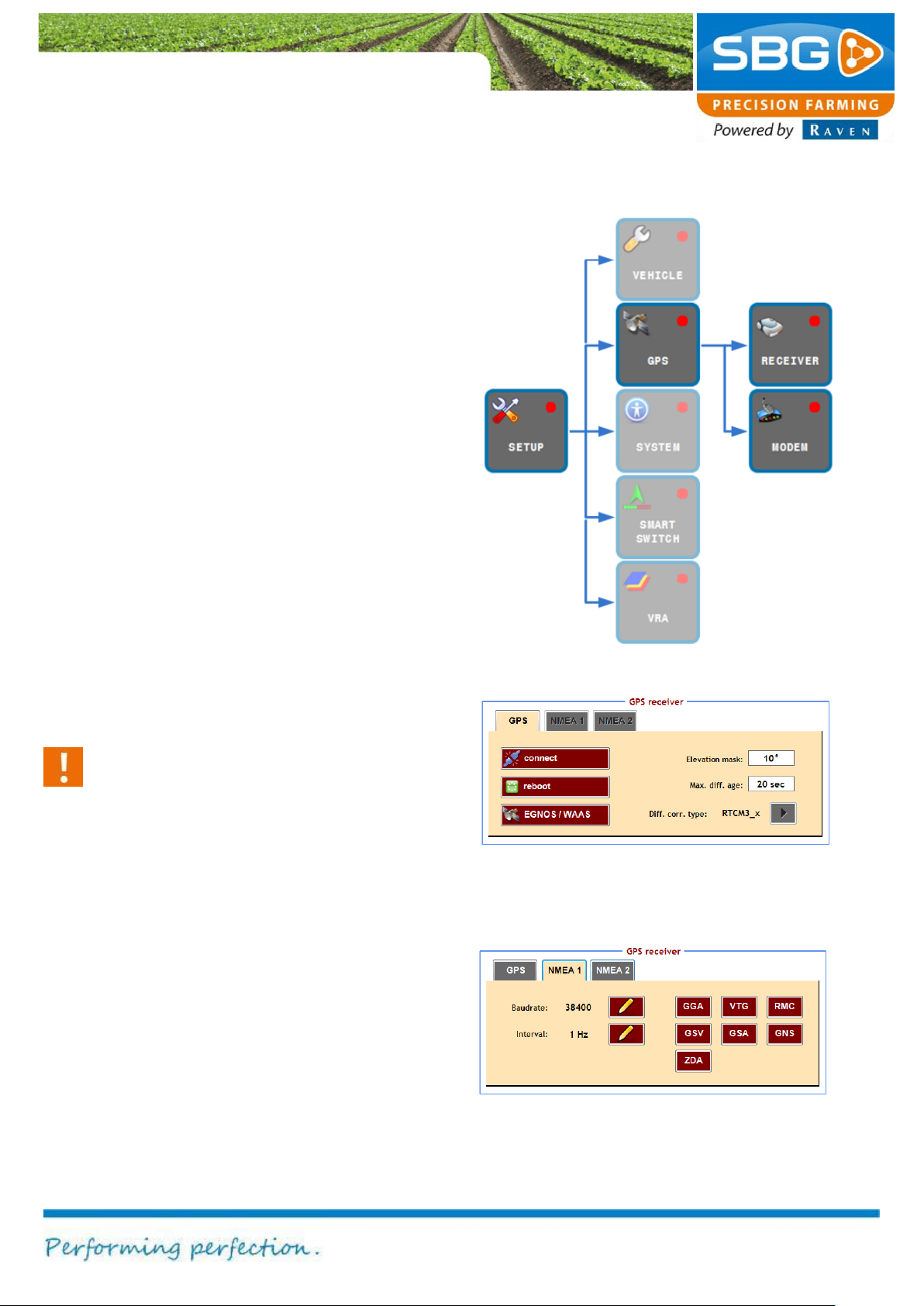
5.2. GPS set-up
The GPS menu comprises all the functions
necessary for configuring the GPS receiver and
the radio and/or GSM modem (Figure 62).
5.2.1. Receiver
Tap on RECEIVER to change the configuration of
the GPS receiver.
The GPS Receiver menu consists of two tabs.
The GPS tab is displayed by default, as shown in
Figure 63.
Tap on Connect if the connection with the GPS
receiver is interrupted. The connection is
interrupted if the clock at the top right of the
screen is coloured red and/or displays 0:00:00.
The reboot key serves to initialise the GPS
receiver and is only intended to be used in
exceptional cases, e.g. when the GPS receiver
displays three boxes (RTK Float) for a longer
period of time.
Caution!
Never tap the connect and reboot keys
without good reason. Frequent initialisation
of the GPS receiver can cause damage to
the device. Always wait long enough for a
signal to be produced after activating the
keys. The system needs time to perform the
action properly.
The EGNOS key can be used for operations with
a low accuracy to apply automatic steering based
only on the EGNOS signal. If this field is tapped it
will turn green, indicating that the operation can be
automatically controlled using EGNOS.
The elevation mask (default setting = 10 º) can
be changed in order to influence the number of
satellites used. Increasing the elevation mask
ensures that fewer satellites are used but with a
Page 46
Settings
Page 46/70 | May 2015 | 2.0
Figure 65 Configuring NMEA2 data
much better signal quality. Decreasing the
elevation mask ensures that more satellites are
used but with a poorer signal quality. The
elevation mask can be increased or decreased in
order to obtain a better RTK fix.
With the Max. diff. age setting it is possible to set
the time period wherein the system can work
without RTK-correction data.
With the Diff. corr. Type setting it is possible to
set the used correction data type.
Tap on NMEA1 to open the NMEA1 tab (Figure
64). NMEA messages can be used to provide
external devices with GPS data such as position,
direction and speed. The messages are
transmitted over a serial interface port (RS-232)
by a 17-pin connector on the GeoStar (icon nr. 7
in Figure 2 or icon nr. 10 in Figure 3).
On the Viper 4 it is possible to connect to a 17-pin
connector if the adapter Viper 4 terminal harness
(SBG13711-11) is used. If a Viper 4 terminal
harness (SBG13711-09) is used the NMEA cable
can be connected to a sub D9-connector with the
label NMEA or VRA.
Tap the different keys to activate the correct
messages (green = active) and set the Baud rate
and Interval.
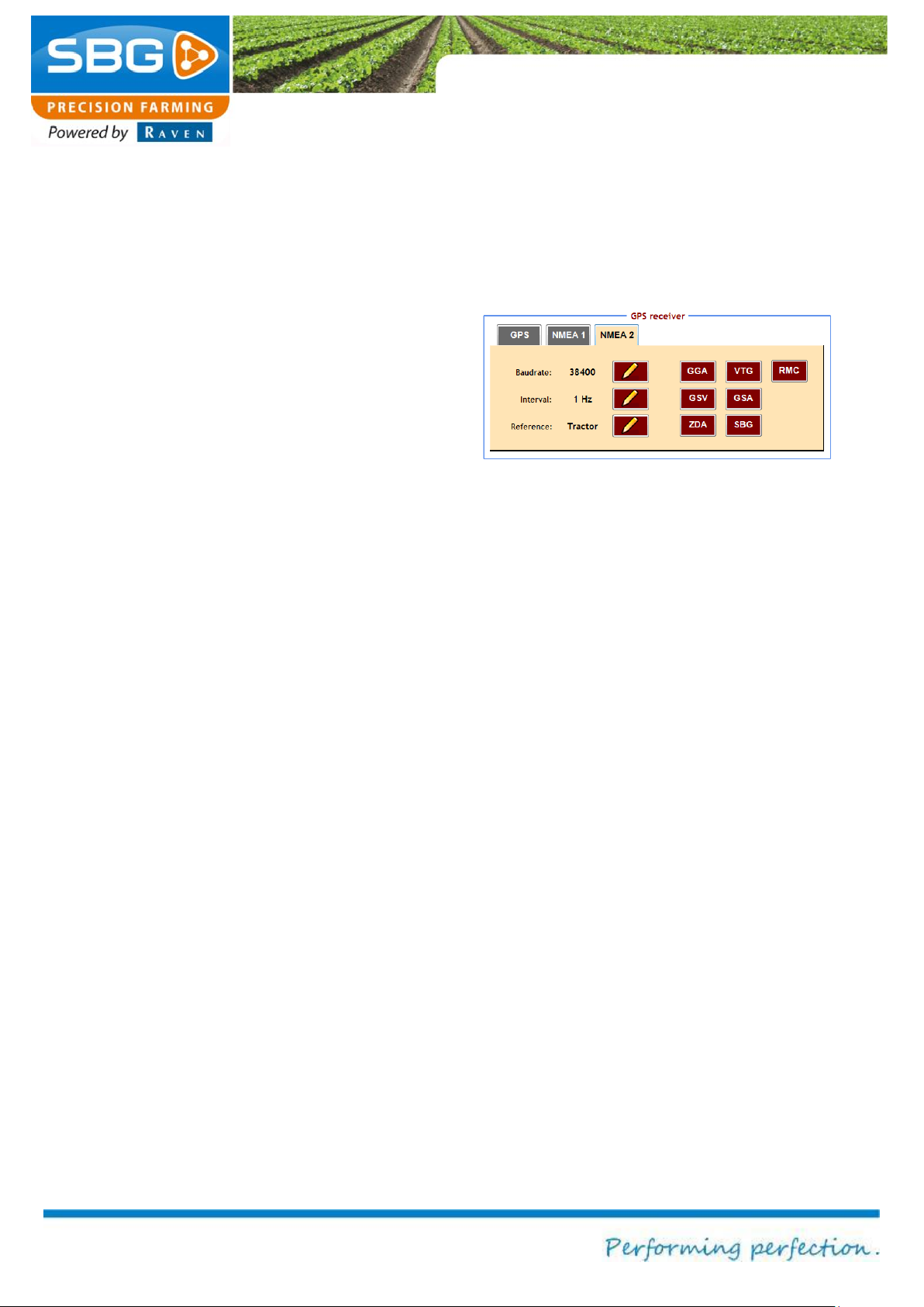
Tap on NMEA2 to open the NMEA2 tab (Figure
65). NMEA2 data is GPS data which is roll
compensated (terrain compensated). Furthermore,
the user can chose from which Reference (tractor
or implement antenna) the data is coming.
Page 47
Settings
Page 47/70 May 2015 I 2.0
Caution!
To use NMEA1 and NMEA2 data a different
cable harness to connect between the field
computer and external device is needed.
Contact you dealer for more information.
The correct data settings can be found in the
operating manual of the external device.
Page 48
Settings
Page 48/70 | May 2015 | 2.0
Figure 67 GeoConnect
Figure 66 Radio modem tab
Figure 68 GeoConnect settings 1
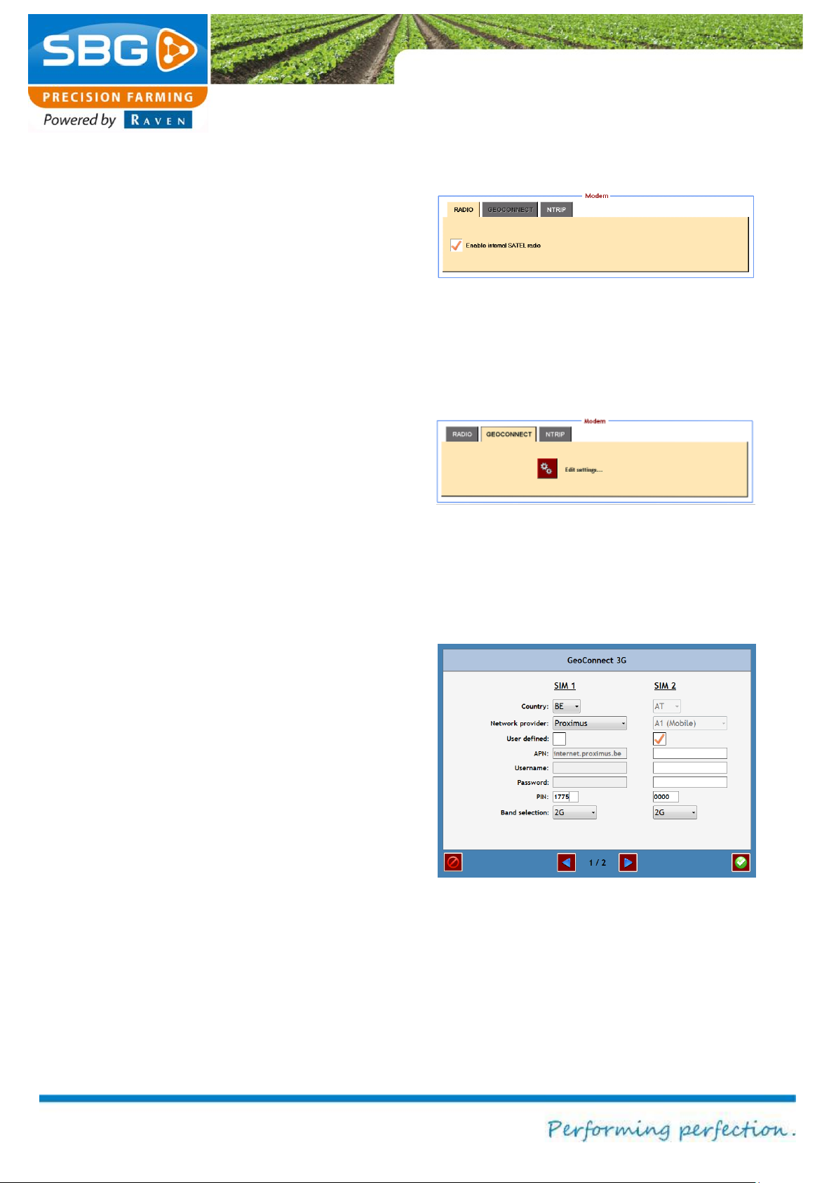
5.2.2. Modem
In the GPS menu tap on MODEM to change the
modem settings (Figure 66). The type of modem
to be used will depend on the type of correction
signal. A radio modem (built-in, if desired) is used
for correction signals over fixed or mobile base
stations. A GSM modem (GeoConnect) is used
for correction signals over an NTRIP network.
The screen of Figure 66 is empty while using a
Geostar terminal. There is a check box, to indicate
whether there is an integrated Satel radio modem
or not, while using a Viper 4. The rest of the
configuration on the Satel radio modem is done by
the Base Manager in the SBGuidance Loader
(chapter 2.2).
The GEOCONNECT tab is only active (Figure 67)
if a GeoConnect modem is connected. Tap on
Edit settings to change the configuration of the
GeoConnect modem.
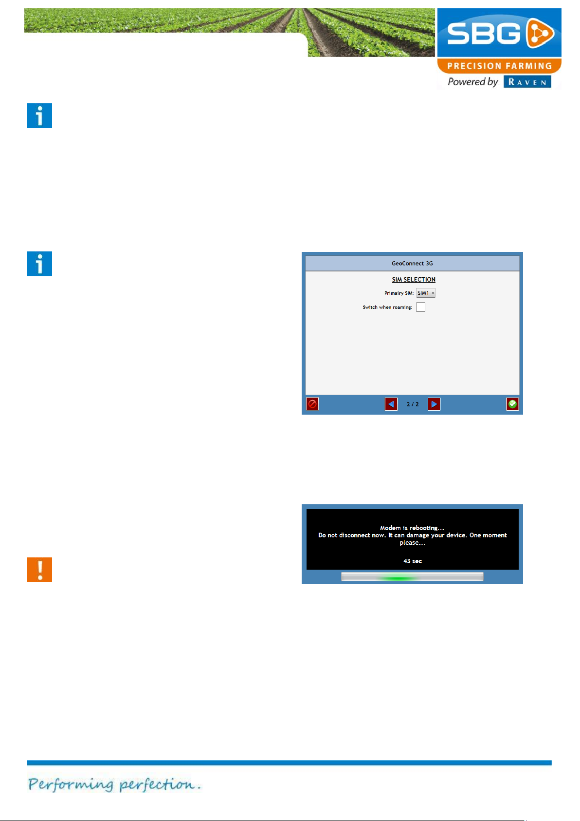
Enter the SIM card data on page 1/2 (Figure 68).
Several providers and their data are already
available for certain countries. If this is the case,
select the country, the correct network provider
and correct PIN code. Other data is entered
automatically. If the desired country and network
provider are not available in the list, select use
defined. This enables the APN (access point
name), username and password to be entered
manually. To obtain these details, please contact
your own GSM network provider. Frequency
band and Selection can be used to select a
connection type: 2G, 3G or AUTO (automatic
selection of available connection type).
Page 49
Settings
Page 49/70 May 2015 I 2.0
Figure 70 GeoConnect initialization
Figure 69 GeoConnect settings 2
Please note!
The SIM card will be blocked if an incorrect
PIN code is entered. The blocked SIM card
can be accessed again after entering the
PUK code. This code can be entered after
the SIM card has been removed from the
GeoConnect device and inserted into a cell
phone.
Please note!
Always check that the SIM card is inserted
into the correct SIM card slot. SIM 1 is the
slot located closest to the metal housing of
the GeoConnect modem.
Go to page 2/2 with the blue arrow (Figure 69).
The Primary SIM determines which SIM card is
used while initialling the system. Select Switch
when roaming in order to use the secondary SIM
card automatically in a foreign country.
Tap on the green checkmark symbol to save the
data, or on the abort symbol at the bottom left of
the screen in order to abort the input (data will not
be saved).
GeoConnect will now reboot (Figure 70). Wait until
GeoConnect starts up for the first time.
Caution!
Do not disconnect the modem during
initialization. This may lead to the loss of
data and may cause irreparable damage to
the device.
Page 50
Settings
Page 50/70 | May 2015 | 2.0
Figure 71 NTRIP
Figure 72 NTRIP configuration 1
Figure 73 NTRIP configuration 2
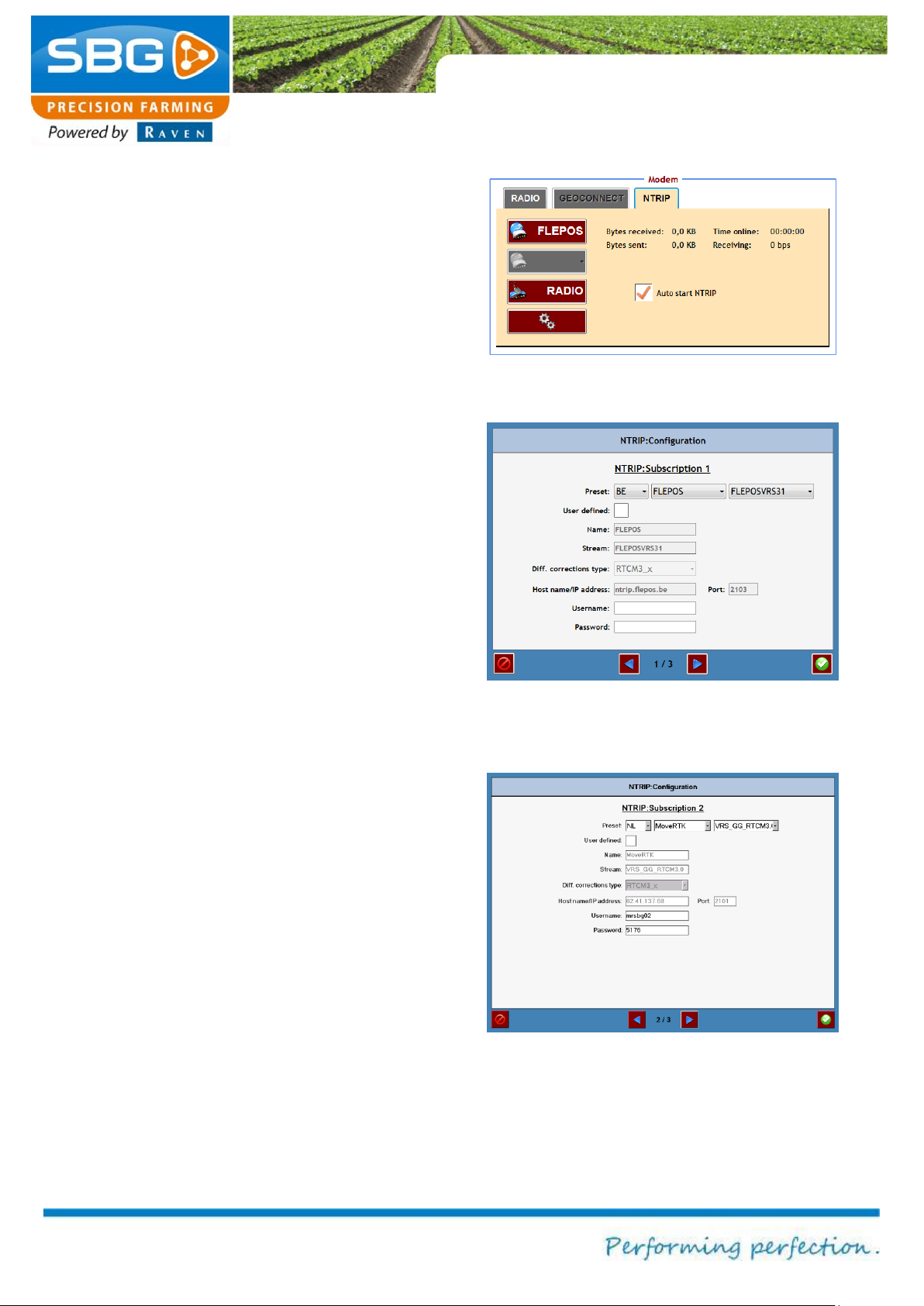
The required NTRIP provider can be selected from
the NTRIP tab (Figure 71). The selected provider
will be highlighted in green.
The connected status is then displayed:
Number of messages received (Bytes received)
Number of message sent (Bytes sent)
Connection speed (Receiving)
Connection time (Time online)
To establish a connection automatically, select
Auto start NTRIP when starting the GPS system.
The NTRIP networks are established by tapping
on the settings key (gearwheel symbol) at the
bottom of the screen (Figure 72).
Configure the settings for the first NTRIP network
in the first window. Networks for specific countries
are also given here under Preselect. If the
preselected connection data are selected, the
parameters for other correction type,
hostname/IP address and port are also entered
automatically. If the desired network connection is
not available in the preselect options, the
parameters can be entered manually after
selecting own entry. Finally, enter the username
and trackword in order to gain access. (All these
data must be obtained from the NTRIP network
provider).
[This step is optional]
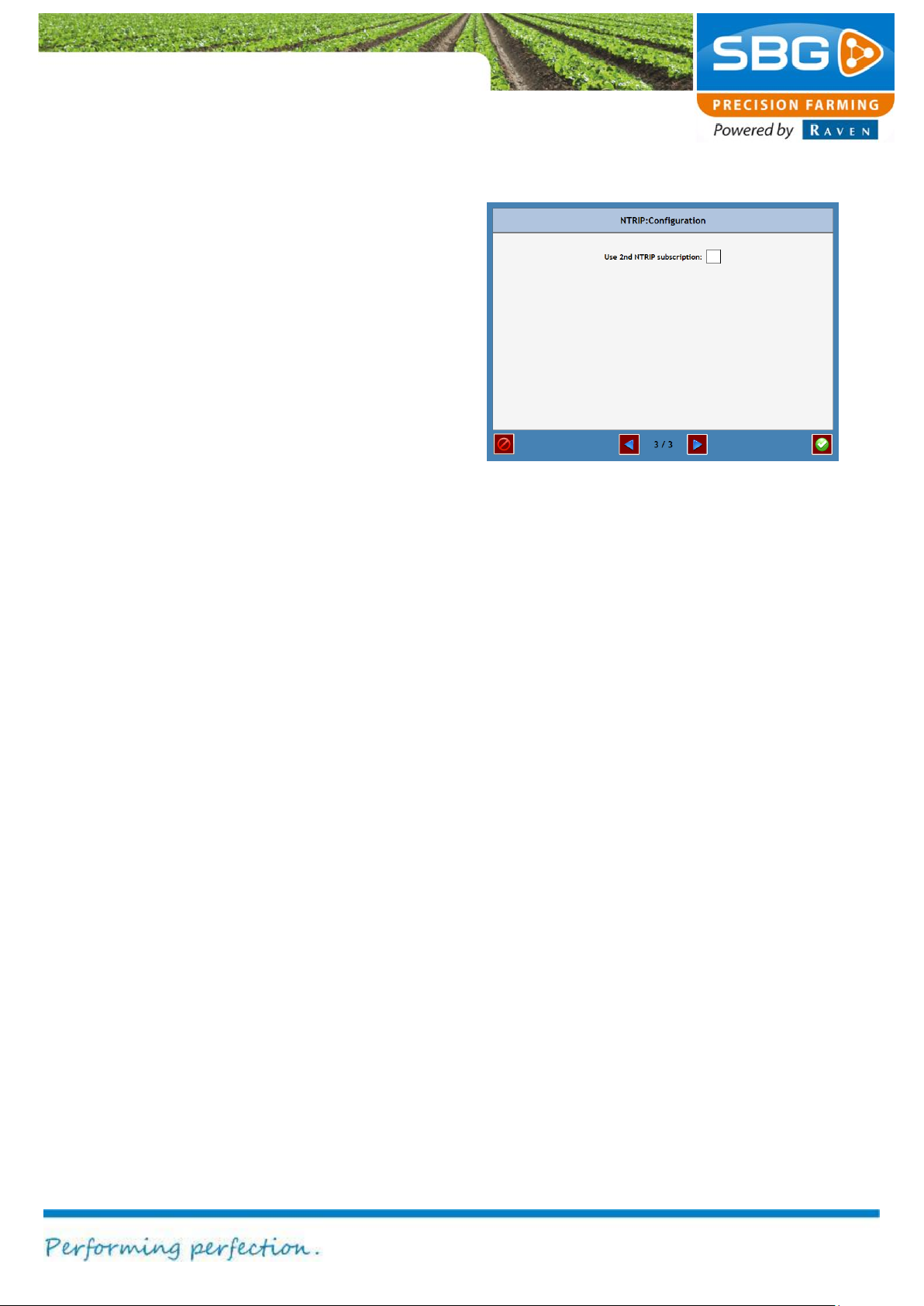
Go to page 3/3 in order to configure a second
NTRIP network (Figure 74). Select Use 2nd
NTRIP subscription and return to page 2/3. Now
configure the second NTRIP network (Figure 73).
Page 51
Settings
Page 51/70 May 2015 I 2.0
Figure 74 NTRIP configuration 3
Tap on the green checkmark symbol to save the
data, or on the abort symbol at the bottom left of
the screen in order to abort the input (data will not
be saved).
Page 52
Settings
Page 52/70 | May 2015 | 2.0
Figure 75 System set-up
Figure 77 Beeper
Figure 76 Display
Figure 78 System
5.3. System set-up
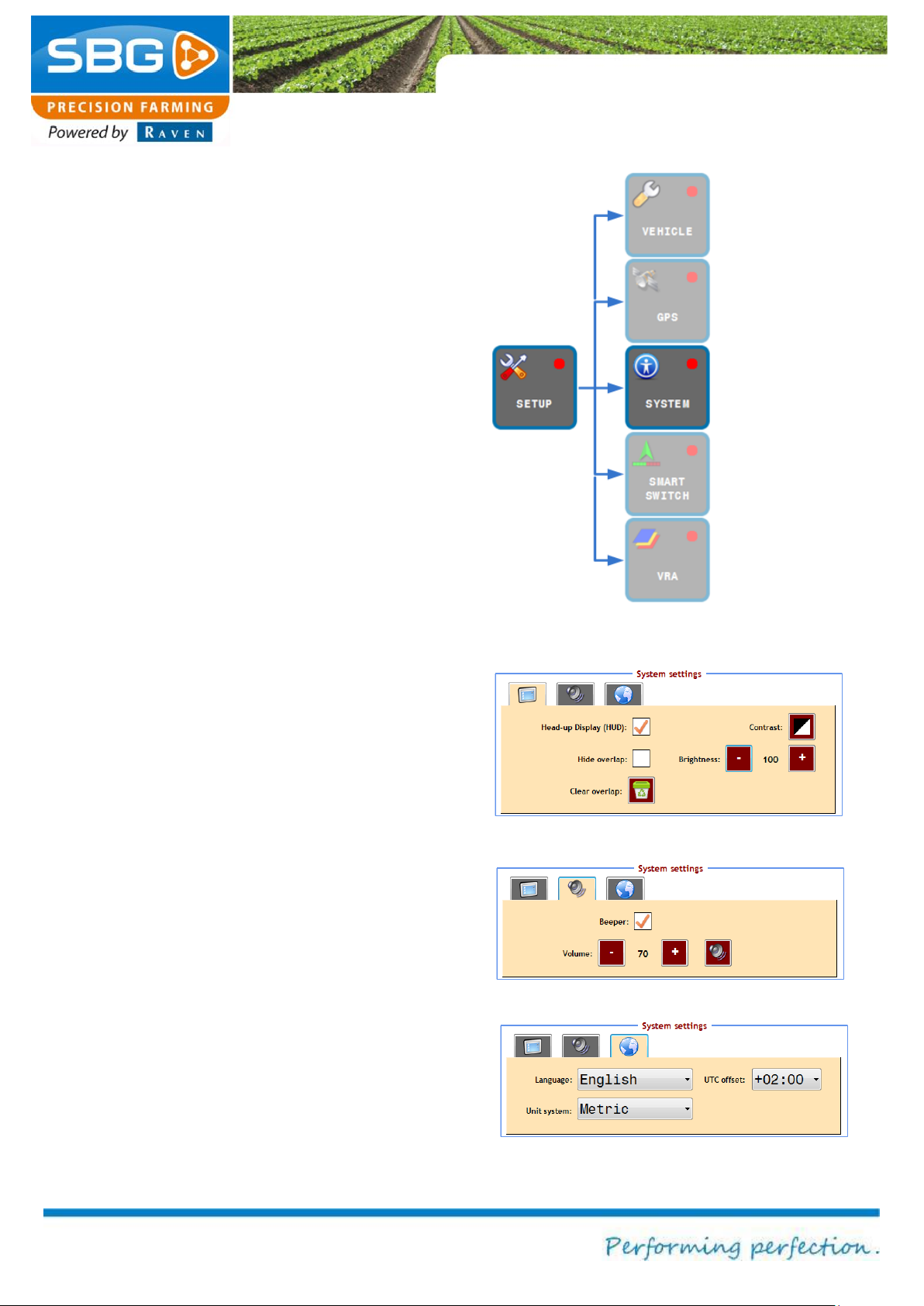
Go to the SYSTEM menu in order to change the
screen and language options (Figure 75).
The Display tab is displayed by default (Figure
76).
Tap on 2D/3D in order to change the field display
(tapping on field display also has the same effect).
Select head-up display (HUD) so that the
position of the Side-Shift cylinder, the disc or the
plough is displayed on the main screen when
controlling the device or plough.
Select Hide overlap to hide the blue colouring on
the screen. Delete overlap can be selected to
delete the blue overlap.
Tap on Contrast to change the background colour
of the field display from black to white and vice
versa. Additionally, use the dim button (on
Geostar terminals) on the right hand side of the
terminal to change the light intensity of the display.
The brightness on a Viper 4 terminal can be
changed with the two keys (‘+’ and ‘-‘) on the right
hand side of the display screen.
Tap on the speaker tab to activate or deactivate
the beeper (Figure 77). The volume can also be
changed.
Tap on the globe tab to change the language,
units (metric/imperial) and the time zone (UTC
offset) on the system (Figure 78).
Page 53
Settings
Page 53/70 May 2015 I 2.0
Figure 79 Setup SmartSwitch
Figure 80 Setup VRA
5.4. SmartSwitch (Section Controller)
With the SMARTSWITCH-key (Figure 79) it is
possible, if present, to set the SmartSwitch section
control. Section control is used to automatically
switch sections, for example on sprayers, seeders,
spreaders and planters.
For a specific SmartSwitch user manual, see
http://www.sbg.nl/support/downloads-support/.
5.5. VRA (Variable Rate Application)
SBGuidance can be configured to simultaneously
control a maximum of 3 external locationdependent devices. Tap on VRA (Figure 80) to
open the application.
The parameters of each of the different devices
can be changed in the individual tabs (depending
on the number of devices connected). However, a
specific connection cable is required to do this.
For further details regarding the use of the VRA
application, please refer to the SBGuidance VRA
quick start operating manual. This manual can be
found at http://www.sbg.nl/support/downloadssupport/.
Page 54
Info
Page 54/70 | May 2015 | 2.0
Intentionally left blank
Page 55
Info
Page 55/70 May 2015 I 2.0
Figure 82 GPS info
CAN bus status
messages
Information on
operating data
Information on
destination point.
Internet
and Google maps
Figure 81 Info menu
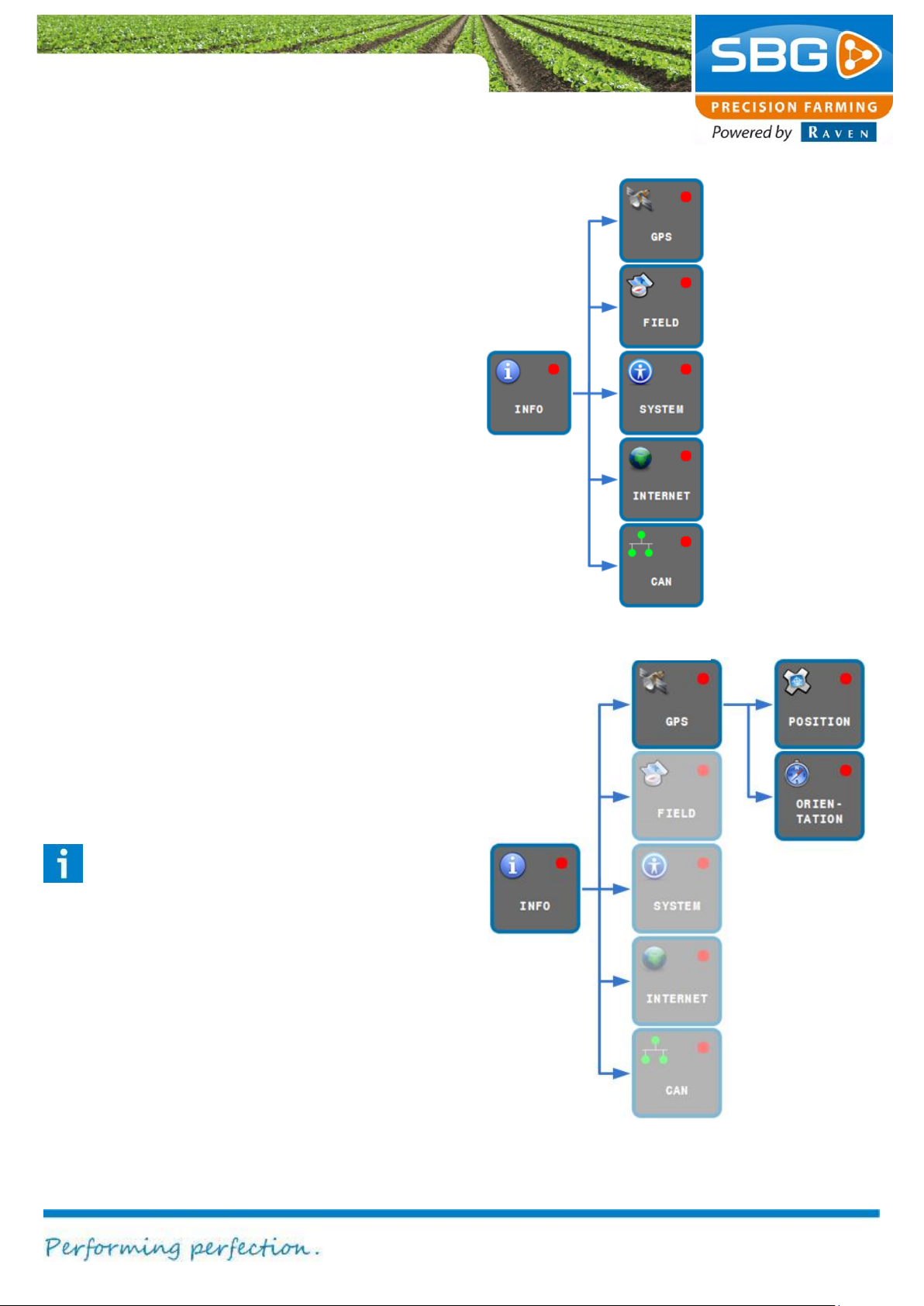
6. Info
Figure 81 shows which functions are invoked after
selecting the INFO key.
It is always possible to abandon a specific
application and to return to the main menu by
tapping on BACK at the top left of the screen.
6.1. GPS info
The GPS can be used to display information
concerning the position or orientation towards the
destination point. Activating the key at the top right
of the screen invokes data regarding POSITION or
ORIENTATION (Figure 82).
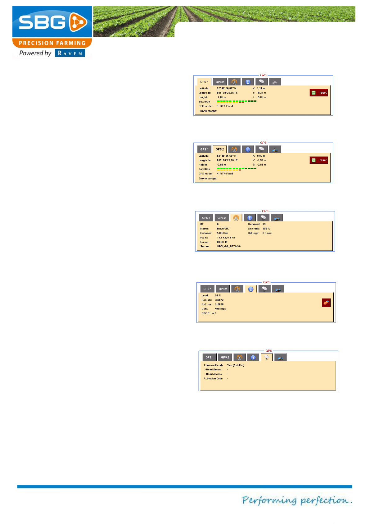
6.1.1. Position
Tap on POSITION in order to display information
on the GPS position. This information is divided
amongst five different tabs: GPS1, GPS2, BASE,
INFO, TERRASTAR and GEOCONNECT.
position and
fields and
System
information:
Licence, error
information
Weather forecast
The GPS1 tab (Figure 83) can be selected in
order to display information on the main GPS
antenna. This is the antenna mounted on the
tractor.
Please note!
The main antenna is the antenna mounted
on the tractor. Connect the main antenna
cable on the GeoStar to the antenna
connection socket closest to the touch-
screen. Connect the main antenna cable on
the Viper 4 to the connection socket
marked with GPS1.
Page 56
Info
Page 56/70 May 2015 I 2.0
Figure 83 GPS1 (main-antenna) info
Figure 84 GPS2 (aux-antenna) info
Figure 85 Base station info
Figure 86 INFO
Figure 87 Terrstar information
Latitude, Longitude and X, Y, Z can be selected
to display the coordinates of the current GPS
position. Elevation displays the GPS elevation.
The Satellite option displays the number of visible
and active satellites available to the system:
bright green: Number of GLONAS satellites
used
dark green: Number of GPS satellites visible
but not used.
yellow: Number of GLONAS satellites used
brown: Number of GLONAS satellites visible
but not used.
GPS mode indicates the signal quality: No
solution, Stand-Alone GPS, SBAS, RTK-Float
or RTK fixed. Any reception problems are
displayed in the error message. Tapping on the
Reset key resets the RTK filter of the GPS
receiver.
The GPS2 tab (Figure 84) can be selected in
order to display information on the auxiliary device
antenna (AUX antenna), if present.
The BASE tab (Figure 85) can be selected to
display information regarding the base station
(transmitter of the correction signal). Distance
displays the distance in metres from the base
station. Received displays the number of
messages received by the base station. Diff. age
displays the amount of time that has lapsed since
the last correction signal was received.
The INFO tab (Figure 86) can be selected to
display the data being received over the
connection by the GPS receiver. These data can
be used by a specialist for diagnosing the cause
or origin of failures.
Page 57
Info
Page 57/70 May 2015 I 2.0
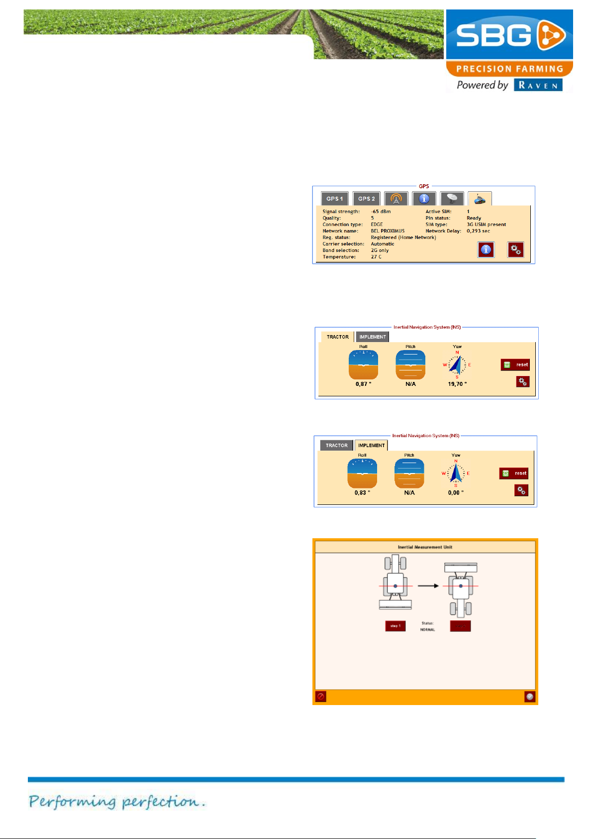
Figure 88 GeoConnect info
Figure 90 Implement orientation
Figure 89 Tractor orientation
Figure 91 Calibrating DynamIQ
The Terrastar tab (Figure 87) indicates if there is
a Terrastar activation on the receiver and some
additional information if the Terrastar activation is
available.
The GEOCONNECT tab (Figure 88) can be
selected in order to display information regarding
the Internet connection (if available). Tap on I to
obtain further information. Tap on the Settings
symbol to change the settings of the GeoConnect.
A detailed explanation of the settings in this menu
can be found in chapter 0.
6.1.2. Orientation
Tap on ORIENTATION to generate data on the
orientation of the vehicle.
The TRACTOR tab (Figure 90) can be selected to
display the Roll, Pitch and Yaw (orientation and
direction) of the tractor. The Reset key is used to
initialise the terrain compensation module
(DynamIQ). This tab is active in the SBGuidance
AUTO and SBGuidance TWIN steering mode.
The IMPLEMENT tab (Figure 90) can be selected
to display the Roll, Pitch and Yaw (orientation
and direction) of the implement/device. The Reset
key is used to initialise the terrain compensation
module (DyanamIQ). This tab is active in the
SBGuidance TWIN and SBGuidance Side-Shift
steering systems.
Tap on the “gear”-sign on the tractor or implement
tab to get information of the corresponding
DynamIQ. Use DynamIQ Heading is standard
selected to determine the direction (Yaw) of
DynamIQ. If this setting is not selected, the
direction is determined on the basis of the GPS
positions.
Tap on Calibrate in order to perform a 2-point
calibration (Figure 91). This mode is selected in
order to determine the level and centre of the
Page 58
Info
Page 58/70 May 2015 I 2.0
tractor. This ensures that the tractor drives back
and forth in the same track and that any
operations are therefore performed consecutively.
Drive to a uniform and level surface (e.g. the
farmyard). Position the tractor next to the
reference point. Tap on Step 1 to define the roll
angle in that direction (heading). The status will
change from NORMAL or Waiting for Heading to
CALIBRATING. Wait for a while until the status
changes to WAITING. Then position the tractor in
exactly the opposite direction (180 degrees
rotation) next to the reference point. Tap on Step
2 to define the roll angle in that direction
(heading). The status will change from WAITING
to CALIBRATING. The straight position is
determined as soon as the status changes again
to NORMAL or Waiting for Heading. Exit the
window by tapping on the checkmark symbol at
the bottom right of the screen.
The centre offset must now be roughly
determined. Check the centre offset (e.g. by
driving back and forth along the track with enabled
automatic steering) and if necessary configure the
SETTING >> VEHICLE >> TUNING in
SBGuidance. Chapter 5.1.1 provides a detailed
explanation of the centre adjustment.5.1.1 Check:
Drive carefully and long enough until the deviation
back and forth is 0 cm!
Please note!
The centre offset must be corrected by half
the correction error.
Page 59
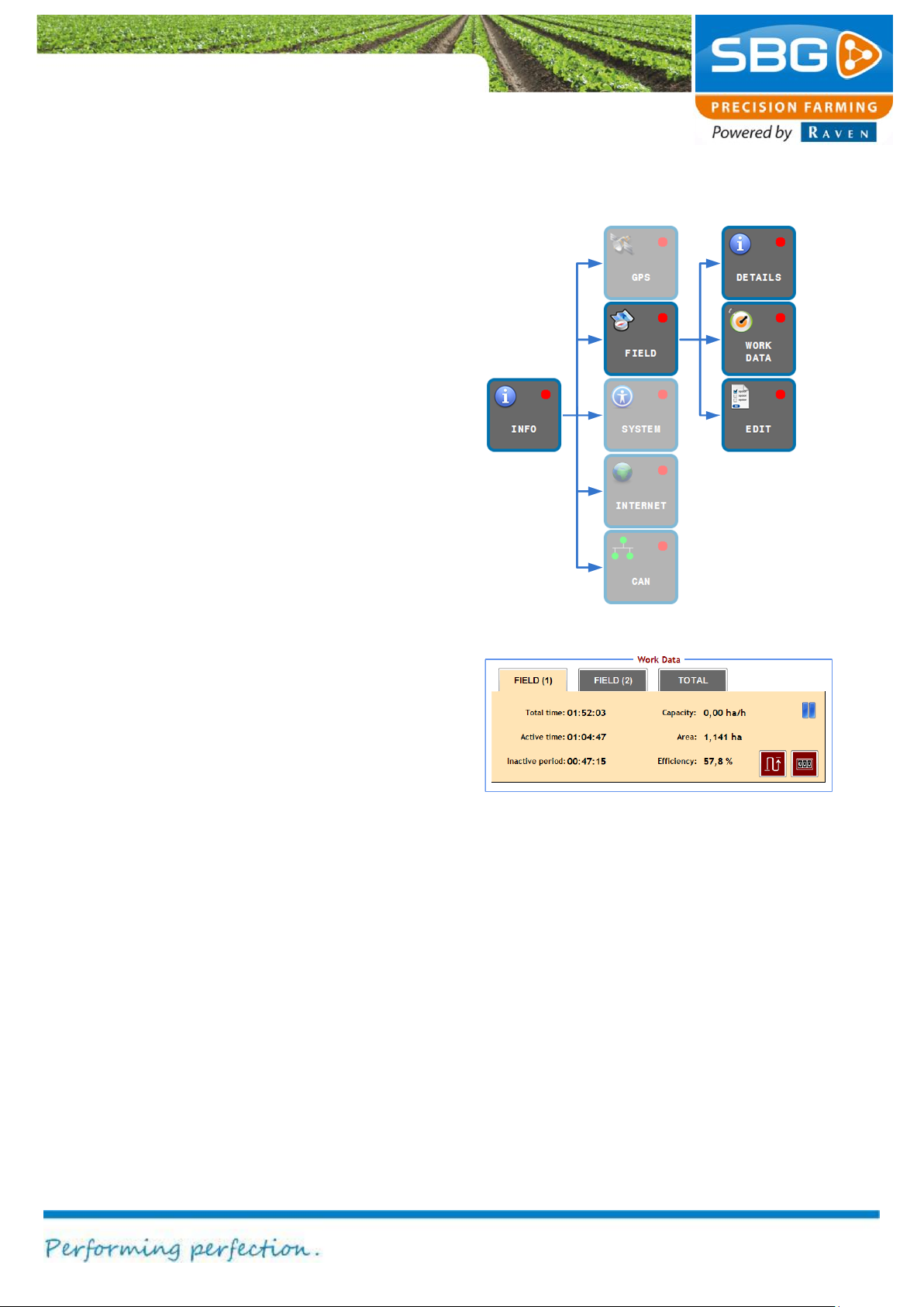
Info
Page 59/70 May 2015 I 2.0
Figure 92 Field info
Figure 93 Work data
6.2. Field info
Tap on FIELD. Three menus are now displayed at
the top right of the screen (Figure 92).
6.2.1. Details
Tap on DETAILS to display data regarding the
field and operation (
6.2.2. Work data
Various data are documented (recorded) in the
WORK DATA menu (Figure 93). There are three
tabs to select from: FIELD (1), FIELD (2) and
TOTAL.
The FIELD (1) and FIELD (2) tabs are linked to
the active field. This means that two different
records can be generated for one field. Both
counters run for this field until each of them are
reset by the RESET key. The ground surface area
displayed in the FIELD (1) tab is linked to the
ground surface area displayed in the top bar of the
main menu.
The counters in the TOTAL tab are counters that
generate a total record of all operations. They are
independent of a field and keep running until they
are reset using the RESET key on the tab itself.
This enables the total work performed on all fields
to be recorded.
The key next to the RESET key is used to change
between recording active distance or recording
active area.
The active time will count when the automatic
steering is activated and the machine is moving. If
one of these conditions is not true the inactive
time will count up.
Page 60
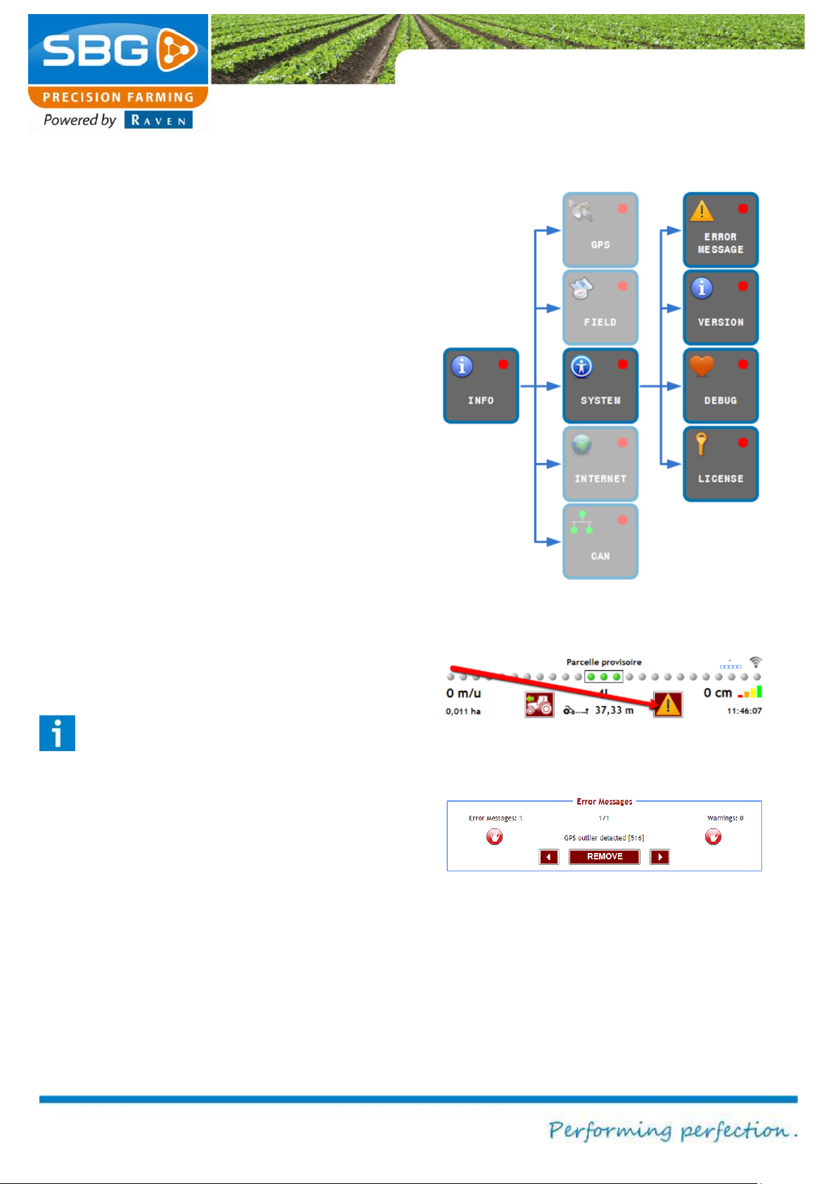
Info
Page 60/70 May 2015 I 2.0
Figure 95 Position of the warning symbol
Figure 96 System error messages
Figure 94 System info
6.2.3. Edit operation
The EDIT key can be selected to change the
parameters of the selected operation. The key is
the same as the EDIT key under FIELD in the
main menu (see chapter 4.5 for a detailed
explanation).
6.3. System info
SYSTEM can be selected to display different
system information (Figure 94).
6.3.1. Error messages
The ERROR MESSAGES tab can be selected to
scroll through a list of (historical) error messages.
If an error message is generated, this is indicated
by a warning symbol (triangle) in the main menu
(Figure 95).
Tap on the warning symbol to go to the error
messages menu (Figure 96).
Error messages can be deleted using the
REMOVE key.
Please note!
Do not delete error messages at random
before noting them down. These error
messages can be useful to product
specialists to trace the cause of a problem
in the event of a failure.
Page 61
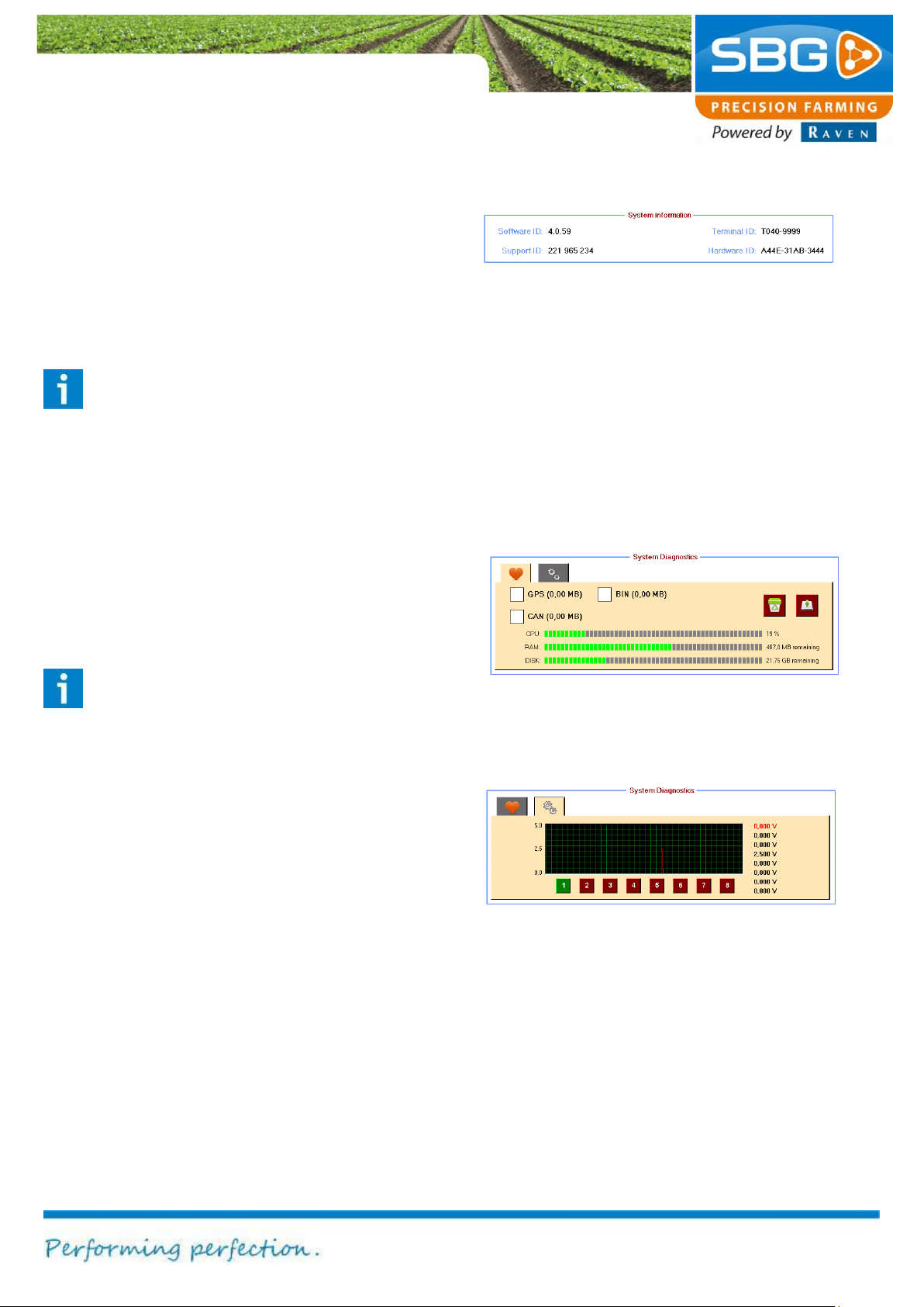
Info
Page 61/70 May 2015 I 2.0
Figure 97 Version info
Figure 98 Data logging
Figure 99 System diagnosis of input voltages
6.3.2. Version
After tapping VERSION, the System information
menu will be displayed at the bottom of the screen
(Figure 97). This menu displays the Software - ID,
Support – ID, Terminal - ID and Hardware - ID.
Tip:
Ensure that you have the Hardware ID
ready when you order a licence for the
activation of a new SBGuidance
application.
6.3.3. Debug
The Debug option enables product specialists to
trace the cause or origin of problems. There are
two tabs in the System diagnostics menu.
Please note!
Any changes to this menu may only be
made following the approval of the dealer or
manufacturer.
The first tab (Figure 98) is that which is typically
displayed by tapping on DEBUG. By checking
GPS/BIN/CAN the GPS/BIN/CAN data will be
saved on the hard disc of the terminal.
The second tab (Figure 99) can be selected to
retrieve the signal strengths of the sensors from
the system.
Page 62
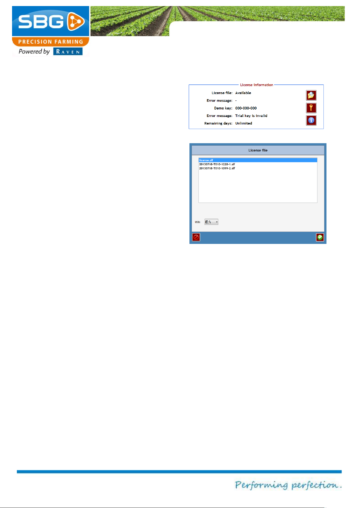
Info
Page 62/70 May 2015 I 2.0
Figure 100 Licence information
Figure 101 Selecting licence datafile
6.3.4. Licence
LICENCE can be selected to display information
on the licences and to install new licences or
temporary licences on the terminal.
The Licence Information menu displays detailed
information regarding the (temporary) licences.
Loading a new licence
A new licence is required when the user requires
steering types or software modules that were not
provided at the time of the initial purchase of the
system. Please apply to your SBG dealer to order
new licences.
The licence data file is accessed as follows:
1. Copy the licence data file from the USB
stick and insert the USB stick into the
terminal.
2. Go to the Licence information menu
(Figure 100) and tap on the right of the
menu on the file symbol. This will open a
new window (Figure 101).
3. Select at the bottom of the screen on USB
the correct drive station (the licence files on
the USB stick will be automatically
displayed).
4. Select the correct data file by tapping on it.
The selection is highlighted in blue.
5. Confirm your selection by tapping on the
confirm symbol at the bottom right.
Page 63
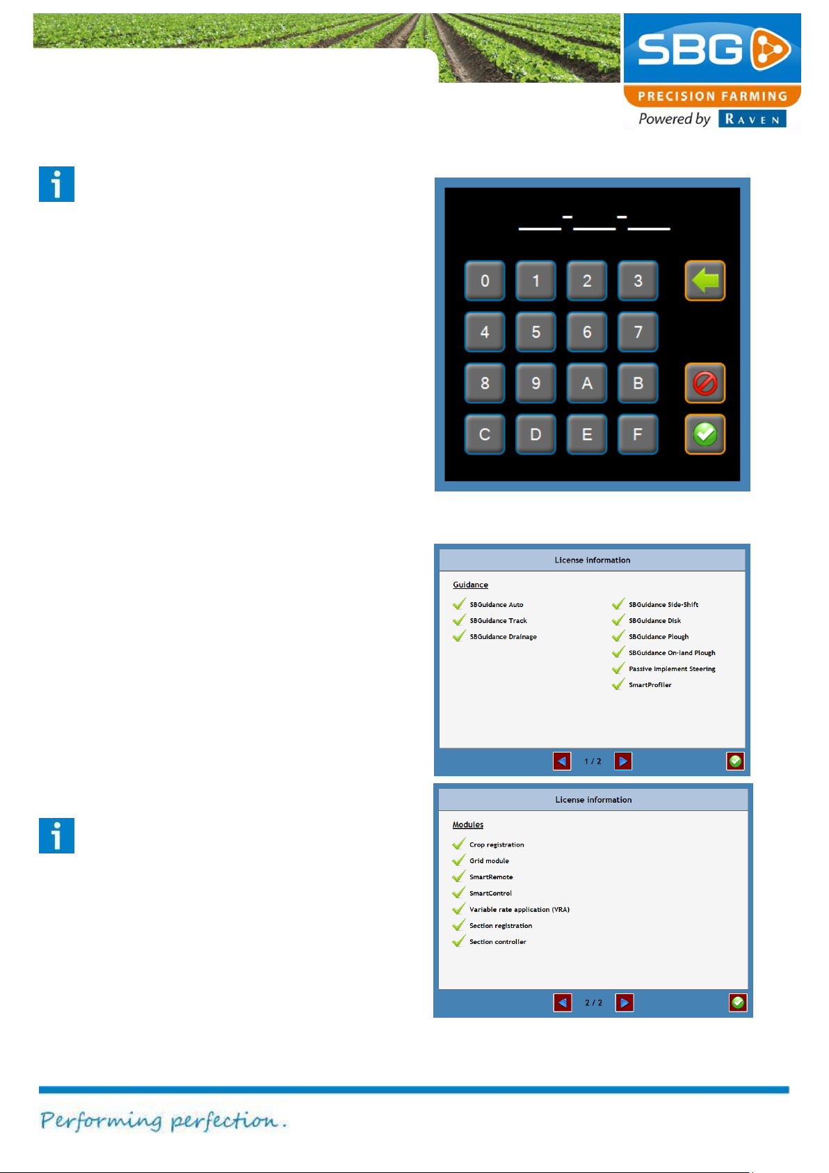
Info
Page 63/70 May 2015 I 2.0
Figure 102 Entering product key for test version
Figure 103 Licence information for steering
systems and software modules
Tip:
Before confirming, check that the serial
number of the terminal is included in the
name of the required licence file (e.g. T010-
1228). The serial number of the terminal
can be found on the sticker behind or to the
left of the terminal and has the following
format: T0XX-XXXX.
Enter product key for test version
A test product key is a code which will
temporarily activate the steering systems or the
software modules. Please apply to your SBG
dealer to order a test product key.
To enter the test product key by going to the
Licence information menu (Figure 100) and
tapping on the key symbol. This will open a new
window (Figure 102). Enter the licence code. Tap
on the confirm symbol after entering the serial
code. The Licence information menu will then
indicate whether the code is valid or invalid.
Displaying current licences
In the Licence information menu (Figure 100)
tap on I at the bottom right in order to check which
steering systems and software modules are
activated (Figure 103).
Please note!
Each licence applies to one terminal only.
Each individual terminal requires its own
licence file.
Page 64
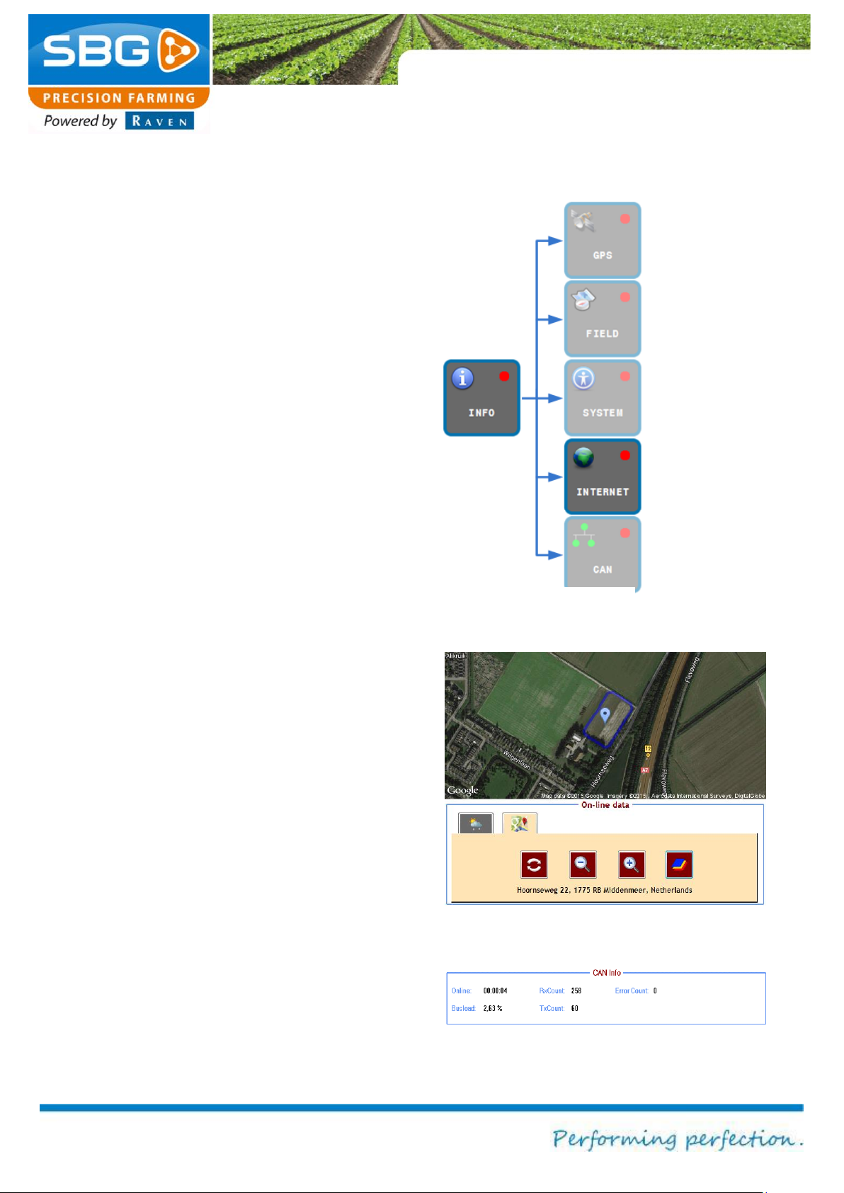
Info
Page 64/70 May 2015 I 2.0
Figure 104 Internet info
Figure 105 Online data maps
Figure 106 CAN info
6.4. Internet info
The INTERNET key (Figure 104) can be selected
to display information from the Internet.
Tap on the WEATHER tab to display the weather
forecast.
Tap on the MAPS tab to display the current
position on Google Maps (Figure 105). The
closest address will be displayed at the bottom of
the screen. The map on the screen can be
updated by tapping on the update symbol. The
plus (+) and minus (-) symbols can be used to
zoom in and out. The map symbol can be selected
to change between the road map and the satellite
display.
6.5. CAN info
The CAN key can be used to display information
on the CAN bus communication (Figure 106).
Page 65
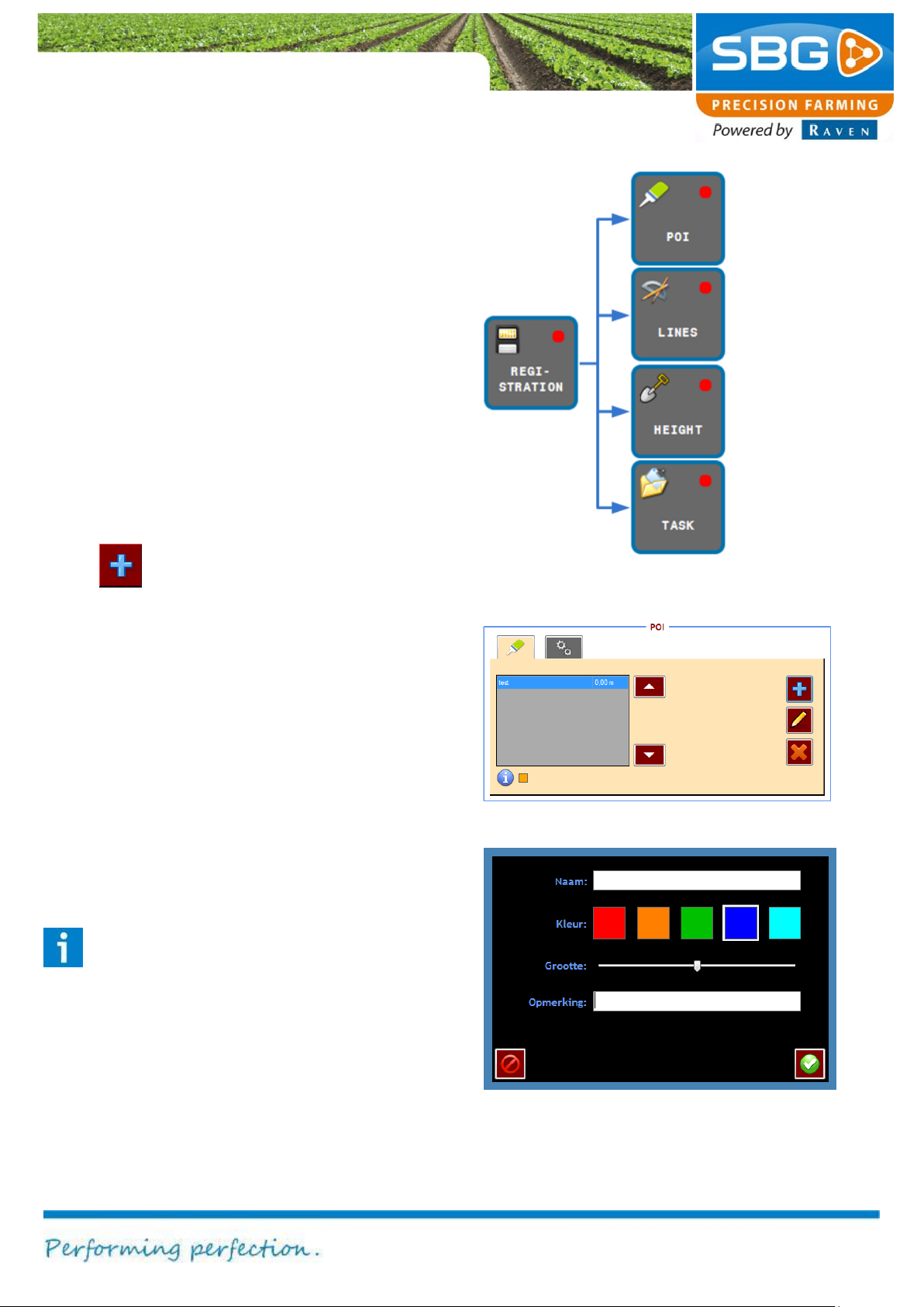
Page 65/70 May 2015 I 2.0
Registration
Defining marked
field
Implement
(optional)
Figure 107 Registration menu
Figure 108 POI menu
Figure 109 Add POI
7. Registration
Figure 107 shows which functions are invoked
after pressing the REGISTRATION key.
7.1. Points of interest
With the POI the Points of Interest (useful position
in a field) screen can be opened. Points of interest
can be set in the active fields by the following
steps:
1. Drive and place the machine in the correct
position in the field.
2. Tap in the POI-screen (Figure 108) on the
key to add a point of interest. A new
screen will occur (Figure 109).
3. Fill in the desired name, colour and size of
the POI. Tap on the blue + icon to add the
POI. In the field display a pyramid will occur
on the current position in the field.
positions on a
Distance
measurements
Elevation
measurements
documentation
The marked position is stored under the current
loaded field. Thus, after reloading the field, the
added points of interest are automatically loaded
and visualised. In the table view of the POI menu
the points of interest are ranked on distance.
Therefore, the nearest point of interest is
visualised at the first row in the table (Figure 108).
Tip:
Use the key MARKED POSITIONS e. g. if
the container of the manure spreader
empties whilst in the middle of an operation.
Page 66
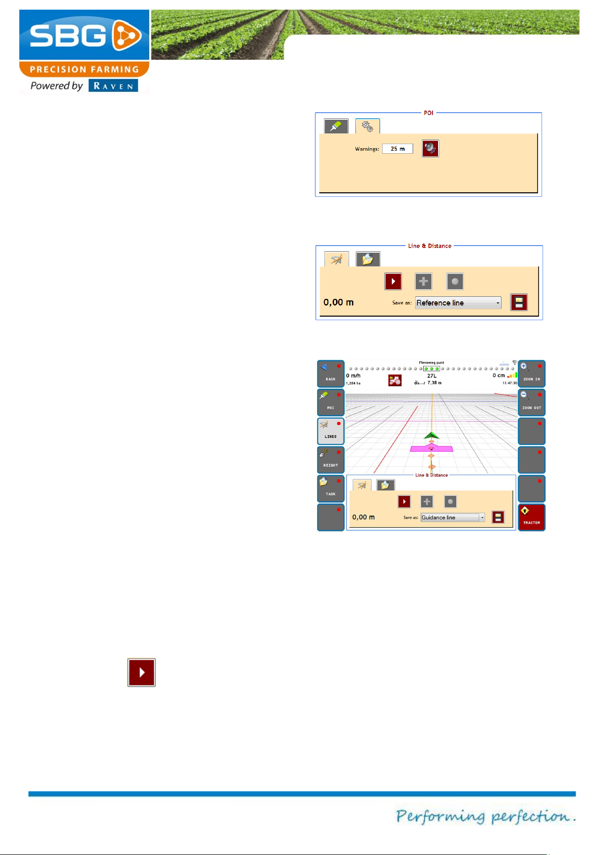
Page 66/70 May 2015 I 2.0
Registration
Figure 110 Proximity warning points of interest
Figure 111 Line & Distance menu
Figure 112 Record curves
In the second tab of the POI menu (Figure 110)
the distance of the proximity warning can be set.
Furthermore, the alarm sound, when approaching
a point of interest, can be deactivated.
7.2. Lines
In the REGISTRATION menu, tap on Lines. In the
Line and Distance (Figure 111) menu additional
reference lines or navigation lines can be added to
the loaded field. Furthermore, a distance can be
measured with this function.
When saving the recorded line as a reference line,
an additional line is added to the field and can be
used as a reference line when adding an
operation to the field. This function can be useful
when there is no suitable side of the contour field
that can be used as a reference line for an
operation. The added reference line can be used
as a main line of the operation.
When saving the recorded line(s) as a navigation
line, an (or more) additional line(s) can be added
to the loaded field. This function can be useful to
record beds or orchards which are not
planted/applied with RTK-GPS. Each bed or tree
line can be recorded separately as an individual
track.
Fulfill the following steps to add a reference or
navigation line:
1. Choose behind “save as” whether you want
to save a reference or navigation line
(Figure 112).
2. Tap on the key to capture the first
point of the line. The recording of the line
starts simultaneously.
Page 67
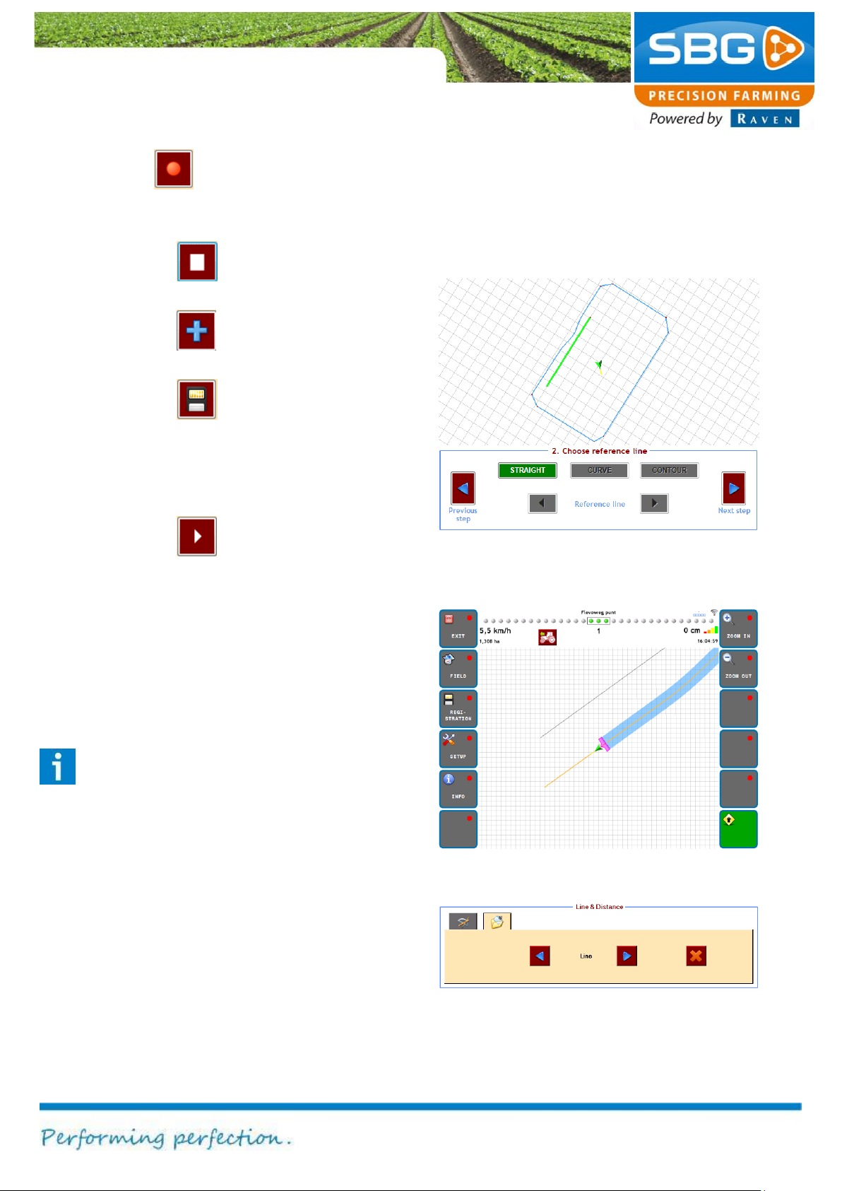
Page 67/70 May 2015 I 2.0
Registration
Figure 115 Delete lines
Figure 113 New operation on added reference line
Figure 114 Steering on navigation line
3. Use the key to start recording a
curve. Tap once more on the same key to
stop the curve recording.
4. Tap on the key to stop a contiguous
line.
5. Tap on the key to add manually a
breakpoint on the line.
6. Tap on the key to saved and add the
line to the loaded field. It is possible to
record several lines before saving the
line(s) to the loaded field. Intermediate
saving is also possible.
7. Tap on the key to capture the first
point of a subsequent line.
If one or more recorded lines are saved as a
reference line, you can add a new operation
based on this reference line(s) by making a new
operation under Field > New operation and
selecting the added reference line in that screen
(Figure 113).
Please note!: to select an added reference
line in a new operation, the recorded line
should be longer than 20 m.
If one or more recorded lines are saved as a
navigation line, you can add a new operation
based on this reference line(s) by making a new
operation under Field > New operation and
selecting the added navigation line in that screen.
In the field view only the recorded navigation lines
will be visualised (Figure 114).
In the second tab of the Line & Distance menu the
recorded and added additional lines can be
deleted. Select the to be deleted lines and tap on
the red X icon (Figure 115).
Page 68
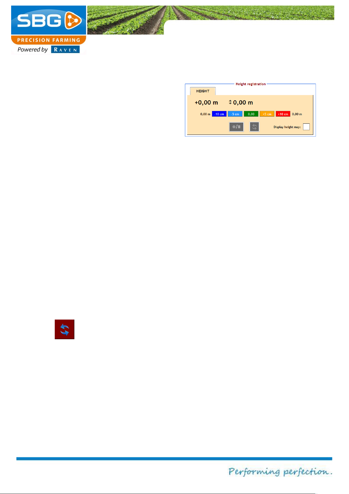
Page 68/70 May 2015 I 2.0
Registration
Figure 116 Activate the height recording
7.3. Height
The SBGuidance software enables the user to
define height measurements on a field. These
height maps can be used with the SBGuidance
Grader software when performing levelling
operations. Height measurements can be taken
whilst performing operations on fields. A contour
field is required.
This is created as follows:
Load a field and an operation.
Go to REGISTRATION >> HEIGHT in the
activate height recording menu (Figure 116)
and check the box next to Display height
map.
You will then be asked if a new height
measurement should be created. Select
YES if a new height map needs to be
created or NO if height data already
recorded should be added.
Tap on the symbol for RECORD/PAUSE in
order to record or to interrupt the recording
of the height data.
The menu can always be exited whilst the
data is being recorded.
The symbol is used to update the
information. The defined height is automatically
saved to the active field after exiting SBGuidance.
Select Show elevation chart in order to display
recorded elevation data in the main menu during
field operations.
Page 69
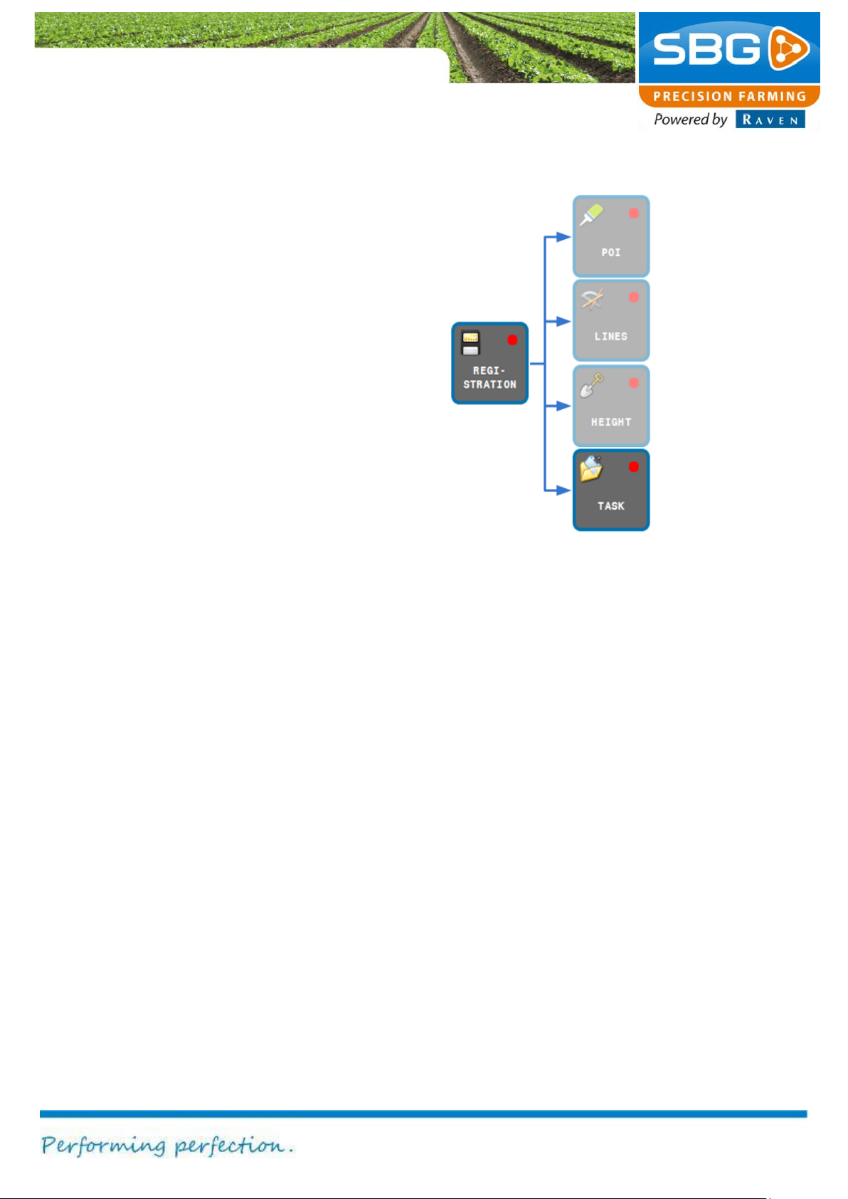
Page 69/70 May 2015 I 2.0
Registration
Figure 117 Task registration
7.4. Crop registration
In the SBGuidance software it is possible to
optionally create a crop registration for a particular
field. These data can be loaded consecutively and
be processed in the desktop program SBGuidance
Office Manager.
For a comprehensive manual covering the options
and application of the crop registration module
and the SBGuidance Office Manager, see
http://www.sbg.nl/en/support/downloads-supporten/.
Page 70

SBG precision farming
Hoornseweg 22
NL-1775 RB Middenmeer
E-Mail: [email protected]
Web: www.sbg.nl
Phone.:+31 (0)227 54 93 00
 Loading...