

INSTALLATION INSTRUCTIONS
P/N: 76-1004
VEHICLE APPLICATION
Year: 2003-07
Make: Dodge
Model: Ram 2500, 3500
Engine: 5.9L Cummins Diesel
Please read the entire product guide before proceeding.
•
Ensure all components listed on page 4 are present.
•
If you are missing any of the components, call our customer support at (909) 947-0015.
•
Do not attempt to work on your vehicle while engine is hot.
•
Make sure the engine is turned off and the vehicle is in Park or the Parking Brake is set.
•
1. With the ignition switched off and the
parking brake set, disconnect the negative
battery cables on both batteries.
TOOLS REQUIRED
10mm, 13mm, 1/2” Wrench & Socket
•
7/16” Deep Socket
•
3/16” & 6mm Hex Drive
•
Torque Wrench (In.lb.)
•
Gasket Remover (Scraper)
•
Vacuum
•
BEFORE YOU START
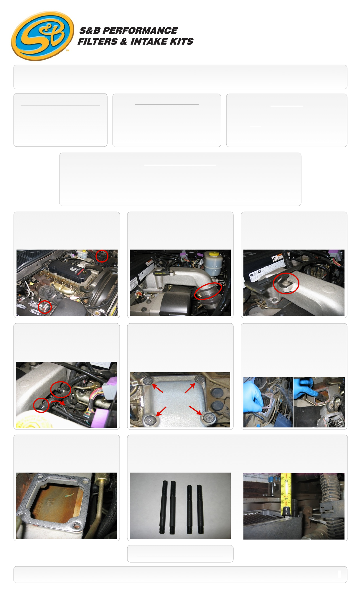
2. Loosen the upper hose clamp at the OE
elbow and disconnect the hump hose from
the elbow. Note: Care should be taken not to
let any debris fall into the boost tube.
CAUTION
Use a 1/4 inch drive ratchet. NOTE: All
required torque specs. are called out in Inch
pounds NOT foot pounds!
3. Remove the bolt that secures the dip
stick tube to the elbow.
4. Remove the lock nut and pull the prong
out that secures the wiring harness to the
elbow and push the harness back away from
the elbow.
7. Place the supplied Graphite Gasket (I) on
the manifold under the heater block, make
sure all four bolt holes in the gasket line up
correctly.
5. Remove the 4 bolts that secure the elbow
to the manifold and remove the elbow from
the vehicle. Careful not to let any debris fall
into the manifold. Note: If the OE bolt threads
were corroded and rust deposits have fallen
through the bolt holes into the manifold use a
vacuum to clean it out.
6. Remove the screw that secures the
ground wire to the manifold to gain access
and to remove both gaskets. A scraper may
be necessary, be careful not to damage the
sealing surface and to not let any debris fall
into the manifold. You may need a vacuum at
this step as well.
8. This kit has 2 long studs (J) and 2 short studs (H), to determine the correct stud length for your
truck, thread each a long and short stud (short threaded end first) into the manifold bolt holes farthest
from the valve cover. Measure the height of the stud from the heater grid block upward. Use the
studs that are approximately 1.125”.
SEE EXPLODED VIEW ON PAGE 4
15461 Slover Ave., Fontana, CA 92337 - Phone: (909) 947-0015 - Fax: (909) 947-0603 - www.sbfilters.com
1
INSTALLATION INSTRUCTIONS (Continued)
P/N: 76-1004
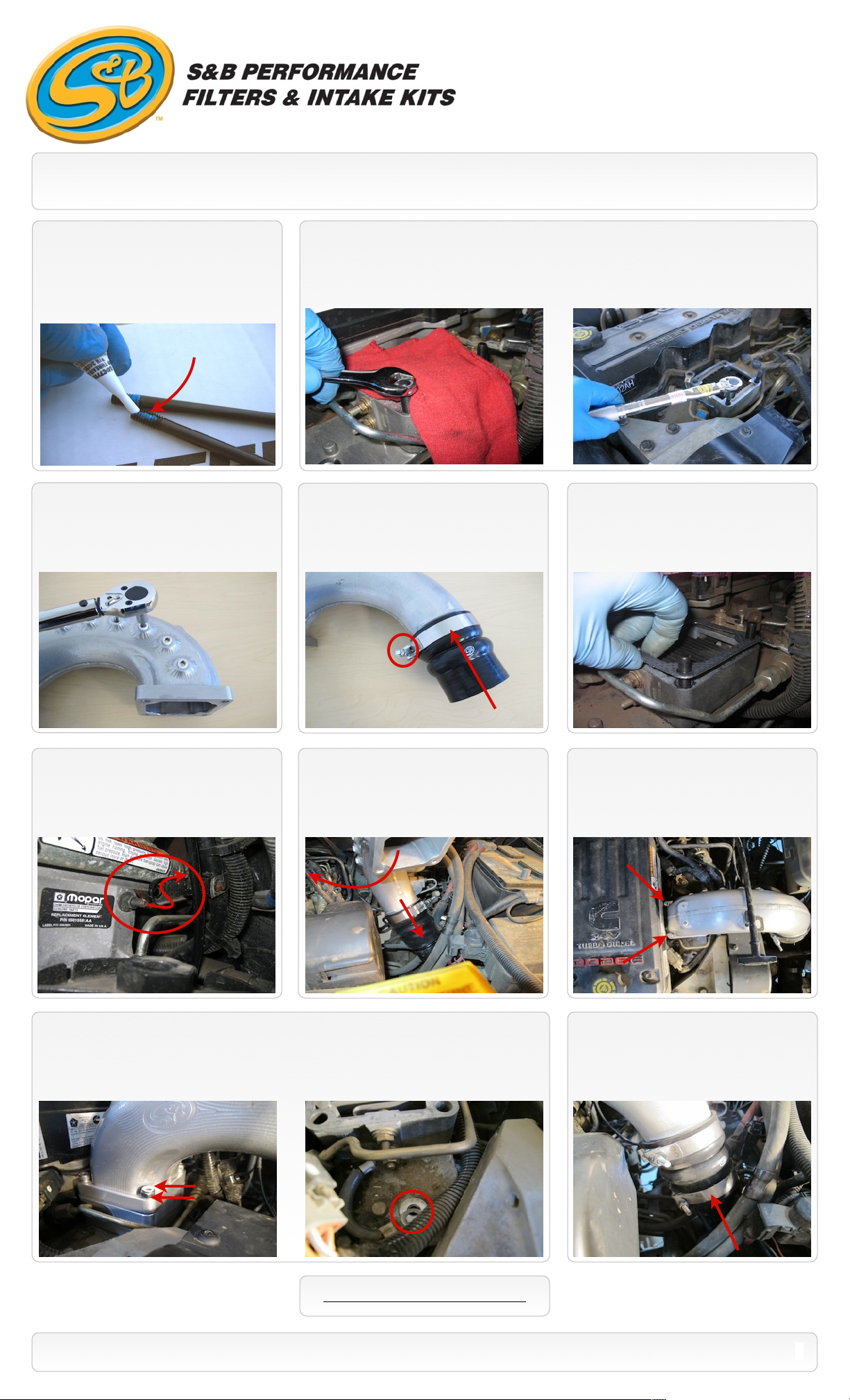
9. Remove the studs and place a small
amount of the supplied Thread Locker (N) to
the correct size Studs (J or H) and thread the
studs by hand into the two bolt holes farthest
from the valve cover. Stage the Socket Cap
Screws (E) by applying Thread Locker also.
Short threaded end
11. Apply a thread sealant such as Teflon
tape to each 1/8” NPT plug (G) and insert the
plugs into the ports you will not use on the
S&B elbow. Use a 3/16 hex socket and
tighten, do not exceed 40 In. lbs.
10. Double nut a stud using the supplied Jam Nuts (K). Turning only the top nut, torque the stud to
40 In. lbs. Remove the Jam nuts and repeat process on the other stud then discard the Jam nuts.
Note: You should first place a clean shop towel in the opening of the intake manifold to prevent any
debris from falling inside.
12. Install the large end of the Silicone
hump hose (O) over the end of the Elbow (F)
and secure using the supplied T-bolt clamp
(P). Torque the clamp to 90 In. lbs.
13. Place the other supplied Gasket (I)
over the Studs on top of the heater grid block.
14. Remove the OE nut at the lower dip
stick tube bracket and carefully push the tube
back about one inch.
15. Slide the OE t-bolt clamp down the
intercooler tube. Push the silicone end of the
elbow assembly down over the intercooler
tube. Then rotate the elbow assembly over
the studs on the heater grid.
17. Place a M8 washer (D) over each stud and thread on the M8 lock nuts (C). Torque both the
lock nuts and the screws to 145 In. lbs. If you use a crow foot to torque the nuts, see the crow foot
calculation on page 3. If there was a ground wire connected to the manifold, place it back in the
same location.
16. Install the two M8 Socket head screws
(E) and M8 washers (D) through the two
holes . Hand tighten for now.
18. Slide the OE t-bolt clamp up onto the
Silicone adapter (O) and torque the clamp to
90 In. lbs.
SEE EXPLODED VIEW ON PAGE 4
15461 Slover Ave., Fontana, CA 92337 - Phone: (909) 947-0015 - Fax: (909) 947-0603 - www.sbfilters.com
2

EMISSIONS STANDARD
The California Air Resource Board (CARB) requires that an E.O. identification label be applied to the vehicle in order to pass a smog
check inspection when a Performance Intake Kit has been installed. You must place the E.O. label provided on or near the intake kit
after installation so that a smog check technician can easily verify the E.O. number. As of April 2009, S&B has never had a product
where CARB denied an exemption request; however, the exemption process with CARB can take as long as 18 months. Check the
status of the exemption process by looking up a specific part number at www.sbfilters.com. The CARB Exemption number and/or
status is listed under the Product Details section for each part number. If the status shows as “Pending,” CARB has yet to issue an
exemption. Products that have not been issued an EO number are street legal in most states, but may not be used on emission
controlled vehicles in the state of California and are for off road use only. If you purchased your kit from S&B Filters directly, we will
automatically mail you your Exemption Sticker when it is issued to us. If you purchased your kit from an authorized S&B Filters Dealer,
log onto our web site and register to receive your Exemption Sticker.
INSTALLATION INSTRUCTIONS (Continued)
P/N: 76-1004
19. Secure the dip stick tube upper bracket to the Elbow. Apply thread locker to the 5/16” x 1/2”
Bolt (B). Then place the Flat Washer (A) on the 5/16” x 1/2” Bolt (B). Place the bolt and washer
through the upper bracket and place the Rubber Washer (M) and the other Flat Washer (A) under
the bracket and thread the bolt into the elbow and secure. Do not exceed 30 In. lbs. If applicable, reattach the dipstick bracket to the stud that was removed in step #14.
21. Reconnect both batteries. Inspect your
installation, make sure the kit is properly
positioned and all fasteners are secure. Affix
the CARB sticker near the intake kit. The
installation is now complete.
PERFORMANCE TESTING
Engage parking brake and start your engine.
•
Listen for abnormal noises. If an air leak is
detected, re-inspect hoses and connections as
they may need to be repositioned and
tightened.
S&B FILTERS recommends that you keep
•
your OE intake elbow in the event it is
required in the future.
In order to maintain your warranty, all
•
connections and components must be
checked periodically for alignment and for
proper tension on all connections. Failure to
do so may void your warranty.
20. Use the supplied Zip-tie (L) to secure the
wiring harness behind the elbow that was
removed in Step #4.
Crow Foot Calculation
NOTE: This is a calculation to adjust your
Torque Wrench for use with a Crow Foot
attached. Please note the end value will never
be higher than the original torque value.
RELATED ITEMS FOR YOUR
PURCHASE
Cold Air Intake System (S&B P/N: 75-5047)
•
Ram Air Scoop (S&B P/N: 75-5049)
•
Heater Delete Block (S&B P/N: 76-1005)
•
SEE EXPLODED VIEW ON PAGE 4
15461 Slover Ave., Fontana, CA 92337 - Phone: (909) 947-0015 - Fax: (909) 947-0603 - www.sbfilters.com
3

ITEM
QTY.
DESCRIPTION
P/N
A2Washer, Flat, 5/16”
AI1073-00
B1Bolt, Hex, 5/16-18x1/2”
AI1078-00
C2Nut, Hex, Nylock, 8mm
AI1401-00
D4Washer, Flat, 8mm
AI1402-00
E2Cap Screw, Socket, M8x90mm
AI1424-00
F1Intake Elbow
AL1174-00
G8Pipe Plug, 1/8”NPT
AI1398-00
H2Stud, Double End, M8x85mm
AI1408-00
I2Gasket, Flat, 4-Hole
AI1532-00
J2Stud, Double End, M8x95mm
AI1400-00
K2Nut, Hex, Jam, 8mm
AI1405-00
L1Zip-Tie, Black, 11”
AI1212-00
M1Rubber Washer
AI1435-00
N1Loctite Thread Locker
AI1406-00
O1Silicone Hump Hose
AI1530-00
P1T-Bolt Clamp,
AG1031-00
EXPLODED VIEW
P/N: 76-1004
OE Heater Block or
S&B Heater Delete
AM0173-00 Rev.A 12/19/11
15461 Slover Ave., Fontana, CA 92337 - Phone: (909) 947-0015 - Fax: (909) 947-0603 - www.sbfilters.com
4

INSTALLATION INSTRUCTIONS Addendum
P/N: 76-1004
How to choose the correct stud length.
This instruction sheet addendum will help you determine the correct stud length to use. This procedure will take place during
steps #8 and #9 of the original installation instructions.
Some of our competitors accommodated a bolt through design to ease the installation process, we feel this to be of a poor
design. Because S&B Filters believes this type of product installation is a one time deal. Our superior design warrants the
additional installation time, as it will yield better performance. S&B Filters gained maximum flow numbers with an aggressive
design that left a small window of clearance for a fixed stud height. This step will add an additional 5 to 10 minutes to the
installation. This kit includes 2 long studs (95mm) and 2 short studs (85mm). To determine the correct length studs for your
application you will need to thread each, a long and short stud (short threaded end first) into the manifold bolt holes farthest
from the valve cover. Measure the height of the stud from the heater grid block upward. Use the stud set that comes closest
to 1-1/8” (1.125”) in height. Remove the studs, place a small amount of the supplied Thread Locker to the correct Studs and
thread the studs by hand into the two bolt holes farthest from the valve cover. Then use the double nut method to secure
and torque the studs to approximately 40 inch lbs. NOT foot lbs.
During this process care should be taken to prevent any parts or debris from falling into the intake manifold by sealing the
opening with duct tape or covering it with a shop towel. If you do get debris inside the manifold you can use a shop-vac or
household vacuum with a small tip attachment to clean out any debris. If you drop a stud or jamb nut into the manifold try
fishing it out with a mechanics magnetic pick-up tool or something similar.
Short threaded end
Intake Elbow Product Warranty
The warranty period for S&B Intake Elbows is 5-Years. Returns are not accepted once the parts have been installed.
Never operate the vehicle (including but not limited to a dyno run) with the hood raised as serious injury and or death could occur!
Warranty Conditions
Product returned for warranty resolution must be accompanied by a Return Material Authorization (RMA) number obtained in advance
from an S&B customer service representative. S&B will be the final authority on all warranty decisions.
The original consumer who purchased the S&B product must also provide proof of purchase to be eligible for the warranty. Those S&B
products used in any type of racing or for off-road use are not covered by the warranty. S&B products that are modified or that are used
on custom applications are also not covered. Products made and/or sold by S&B on a private label basis are also not covered by the
warranty.
This warranty shall not apply to any unit which has been improperly stored or installed; subjected to misapplication, improper operating
conditions, accidents, or neglect; or which has been improperly repaired or altered or otherwise mistreated by the owner or his agent.
Warranty Coverage
S&B Filters, Inc. (S&B) warrants to the original purchaser that any parts purchased shall be free from defects in material and
workmanship. A defect is defined as a condition that would render the product inoperable. This warranty does not cover deterioration of
plating, paint or any other coating. S&B’s liability is limited to the repair or replacement, at S&B’s option, of any warrantable product
returned prepaid with a complete service history and proof of purchase to the factory. A valid proof of purchase is a dated bill of sale.
Repaired or replaced product will be returned to the customer freight collect. Accepted warranty units which have been replaced become
the sole property of S&B. Mileage is not a factor. All S&B products are subject to the provisions stated herein regardless of mileage.
Except as set forth in this warranty, S&B disclaims any implied warranty, including implied warranties of merchantability and fitness for
a particular purpose. S&B also disclaims any liability for incidental or consequential damages including but not limited to, repair
labor, rental vehicles, hotel costs or any other inconvenience costs. This warranty is in lieu of all other warranties or guarantees,
either expressed or implied, and shall not extend to any consumer or to any person other than the original purchaser residing within the
boundaries of the continental U.S. or Canada.
Warranty does not cover conditions where heat-damage resulted due to overly-rich fueling conditions.
15461 Slover Ave., Fontana, CA 92337 - Phone: (909) 947-0015 - Fax: (909) 947-0603 - www.sbfilters.com
5
 Loading...