

Page 1
SBE 38 Digit al Oceanographic Thermometer
With RS-232 or optional RS-485 Interface
User’s Manual
Sea-Bird Electronics, Inc.
1808 136
Bellevue, Washington 98005 USA
Telephone: 425/643-9866
Fax: 425/643-9954
E-mail: seabird@seabird.com Manual Version #006, 03-14-03
Website: www.seabird.com Firmware Version 1.2 and later
th
Place NE
Page 2

Limited Liability Statement
Extreme care should be exercised when using or servicing this equipment. It should be used or serviced
only by personnel with knowledge of and training in the use and maintenance of oceanographic
electronic equipment.
SEA-BIRD ELECTRONICS, INC. disclaims all product liability risks arising from the use or servicing
of this system. SEA-BIRD ELECTRONICS, INC. has no way of controlling the use of this equipment
or of choosing the personnel to operate it, and therefore cannot take steps to comply with laws
pertaining to product liability, including laws which impose a duty to warn the user of any dangers
involved in operating this equipment. Therefore, acceptance of this system by the customer shall be
conclusively deemed to include a covenant by the customer to defend, indemnify, and hold SEA-BIRD
ELECTRONICS, INC. harmless from all product liability claims arising from the use or servicing of
this system.
2
Page 3

Table of Contents
Table of Contents
Section 1: Introduction....................................................................................4
About this Manual .............................................................................................4
How to Contact Sea-Bird...................................................................................4
Quick Start.........................................................................................................4
Unpacking SBE 38.............................................................................................5
Section 2: Description of SBE 38....................................................................6
System Description............................................................................................6
Specifications.....................................................................................................7
Dimensions and End Cap Connector.................................................................8
Baud Rate and Cable Length .............................................................................8
Section 3: Preparing SBE 38 for Deployment ...............................................9
Installing Software.............................................................................................9
Power and Communications Test ......................................................................9
Test Setup...................................................................................................9
Test...........................................................................................................10
Section 4: Deploying and Operating RS-232 SBE 38..................................13
Sampling Modes..............................................................................................13
Polled Sampling........................................................................................13
Continuous Sampling................................................................................14
Command Descriptions....................................................................................15
Data Output Formats........................................................................................17
Deployment......................................................................................................17
Recovery..........................................................................................................17
Section 5: Routine Maintenance and Calibration.......................................18
Corrosion Precautions......................................................................................18
Connector Mating and Maintenance................................................................18
Sensor Calibration............................................................................................19
Glossary..........................................................................................................20
Appendix I: Functional Description.............................................................21
Sensor Interface...............................................................................................21
Settings ............................................................................................................21
Appendix II: Electronics Disassembly/Reassembly....................................22
Appendix III: RS-485 Interface....................................................................23
Operation Description......................................................................................23
Command Descriptions....................................................................................24
RS-485 Commands...................................................................................24
All Other Commands................................................................................25
Data Output Formats........................................................................................25
Wiring..............................................................................................................26
Conversion of RS-232 to RS-485 or RS-485 to RS-232..................................26
Appendix IV: Command Summary.............................................................27
Appendix V: Replacement Parts ..................................................................28
Index................................................................................................................29
3
Page 4

Section 1: Introduction
Section 1: Introduction
This section includes contact information, Quick Start procedure, and photos
of a standard SBE 38 shipment.
About this Manual
This manual is to be used with the SBE 38 Digital Oceanographic
Thermometer.
It is organized to guide the user from installation through operation and data
collection. We’ve included detailed specifications, command descriptions,
maintenance and calibration information, and helpful notes throughout
the manual.
Sea-Bird welcomes suggestions for new features and enhancements of our
products and/or documentation. Pl ease e-mail any comments or suggestions to
seabird@seabird.com.
How to Contact Sea-Bird
Quick Start
Sea-Bird Electronics, Inc.
1808 136
Bellevue, Washington 98005 USA
Telephone: 425-643-9866 Fax: 425-643-9954
E-mail: seabird@seabird.com Website: http://www.seabird.com
Business hours:
Monday-Friday, 0800 to 1700 Pacific Standard Time
Except from April to October, when we are on summer time
Follow these steps to get a Quick Start using the SBE 38 with a standard
RS-232 interface. The manual provides step-by-step details for performing
each task:
1. Test Power and Communications (see Section 3: Preparing SBE 38
2. Deploy the SBE 38 (see Section 4: Deploying an d Operating RS-232 SBE 38):
For an SBE 38 with optional RS-485 interface , see Appendix III: RS-485
Interface for details.
th
Place Northeast
(1600 to 0100 Universal Time)
(1500 to 0000 Universal Time)
for Deployment).
A. Establish setup parameters.
B. Use one of the following sequences to start sampling:
• If AUTORUN=N: GO to start sampling continuously now, or
TS or TH to take a single sample.
• If AUTORUN=Y: Apply power to start sampling
continuously now.
C. Deploy SBE 38.
4
Page 5
Section 1: Introduction
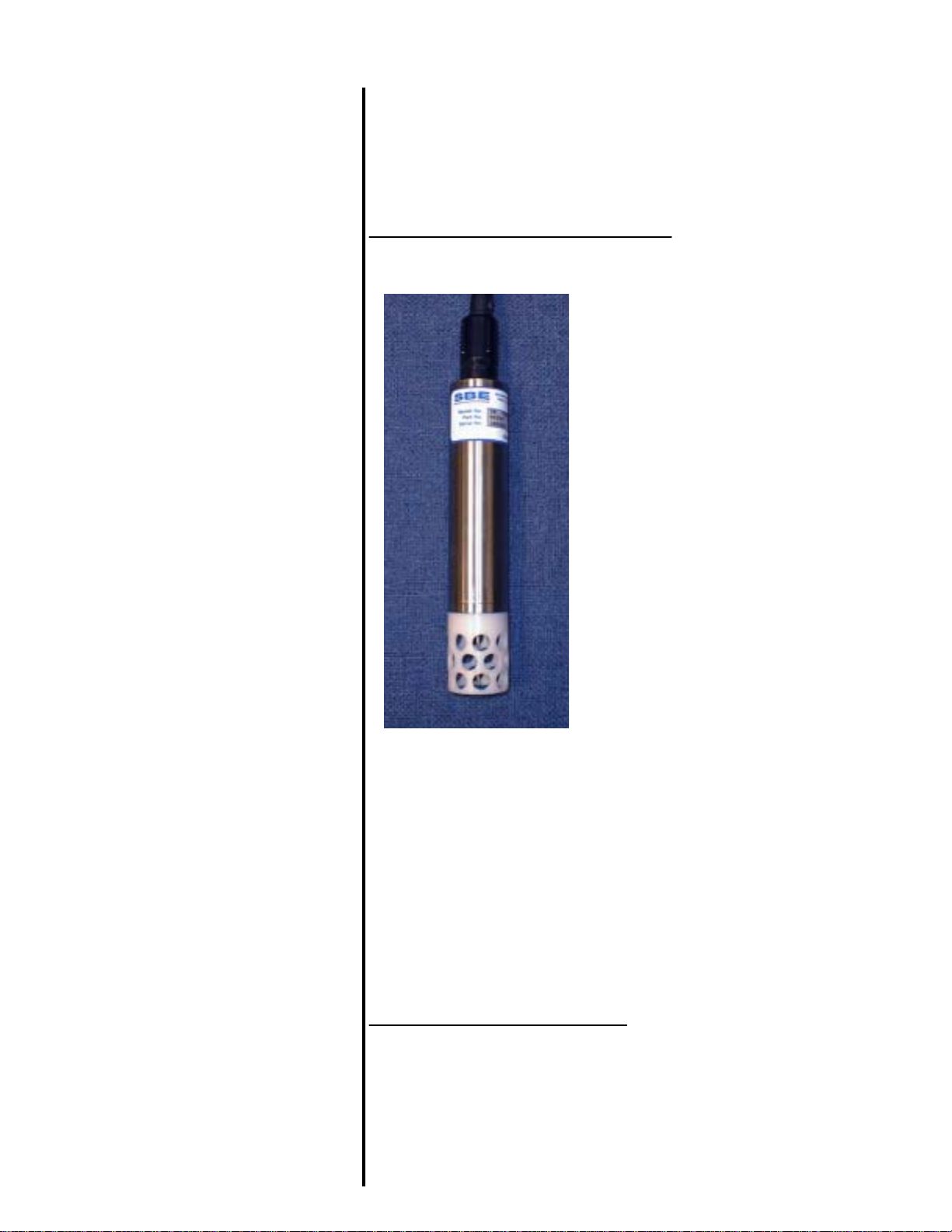
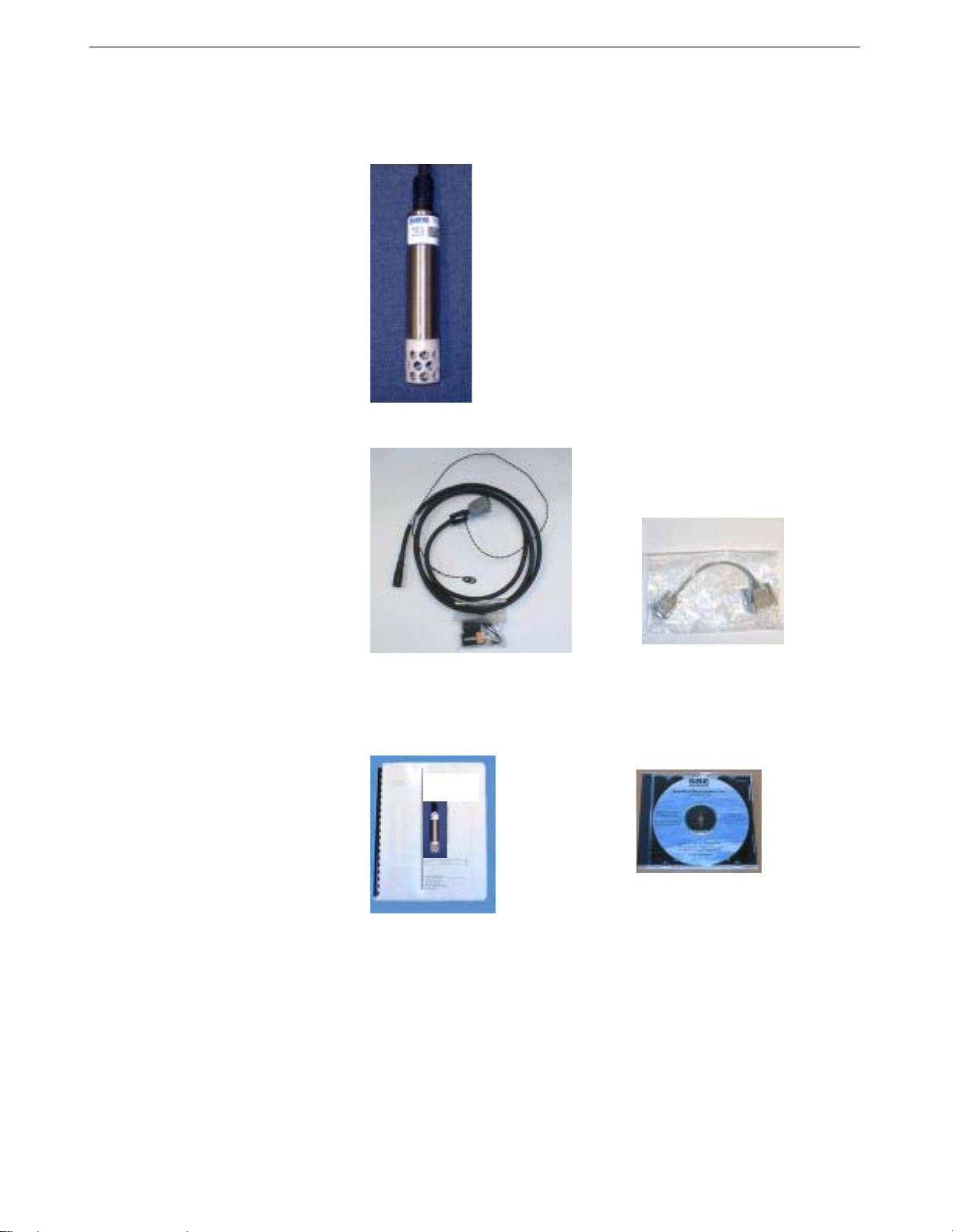
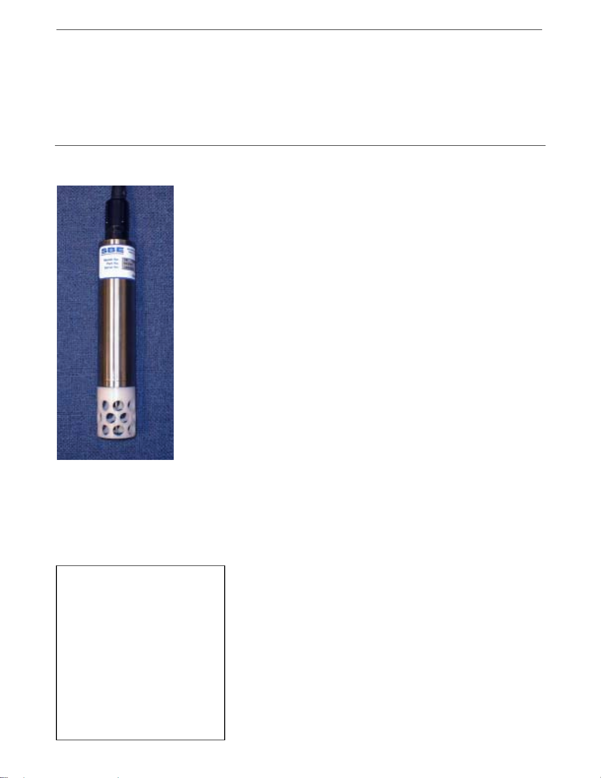
Unpacking SBE 38
Shown below is a typical SBE 38 shipment.
I/O Cable with 9V battery snap
connector and 9V battery
User Manual
SBE 38 Digital
Oceanographic
Thermome ter
SBE 38
25-pin to 9-pin adapter
Software, and Electronic Copies of
Software Manuals and User Manual
5
Page 6
Section 2: Description of SBE 38
Section 2: Description of SBE 38
This section describes the functions and features of the SBE 38, including
specifications and dimensions.
System Description
Sophisticated A/D acquisition electronics, ultra-stable thermistor, and state-ofthe-art calibration provide the standards-level performance of an expensive
AC bridge and platinum thermometer at a small fraction of the cost. The
SBE 38 is unaffected by shock and vibration, has high accuracy and stability,
and is easy to use. It has a rugged, corrosion-proof, 10,500 meter (34,400 foot)
titanium pressure housing. Real-time temperature data is transmitted in ASCII
characters (in °C or raw counts) via an RS-232 or optional RS-485 serial
interface for display or logging by PC or data logger.
The standard measurement range is -5 to +35 °C. An optional range of -5 to
+50 °C is available at slightly reduced accuracy and resolution. For the
standard range, absolute accuracy is better than 0.001 °C (1 mK) and
resolution is approximately 0.00025 °C (0.25 mK). Each sensor includes
certification that demonstrates drift of less than 0.001 °C (1 mK) during a
six-month period.
Applications include calibration baths, oceanographic/aquatic research, and
environmental monitoring.
The SBE 38 operates in one of three ways:
• RS-232 (full duplex) with one SBE 38 connected to the interface
• RS-485 (half duplex) with one SBE 38 connected to the interface
• RS-485 (half duplex) with several RS-485 sensors sharing one pair
of wires
On power-up, the SBE 38 reads its EEPROM, which includes calibration
coefficients and other setup information. As programmed, the SBE 38 samples
and transmits temperature continuously, or waits for a command to begin
sampling. Note that for RS-485 applications with several sensors sharing one
pair of wires, the SBE 38 cannot sample continuously.
The SBE 38 is frequently integrated as a remote temperature sensor with one
of our thermosalinograph instruments (SBE 21 Thermosalinograph or SBE 45
MicroTSG), to provide accurate sea surface temperature. See the manuals for
Notes:
• Sea-Bird also supplies a DOS
software package, SEASOFT-DOS,
which can be used with the SBE 38.
However, this manual only details
use of the Windows software with
the SBE 38.
• Help files provide detailed
information on the use of
SEATERM, SEASAVE, and SBE
Data Processing.
• Separate software manuals on
CD-ROM contain detailed
information on the setup and use of
SEASAVE, SBE Data Processing,
and SEASOFT-DOS.
those instruments for integration information.
The SBE 38 is supplied with a powerful Win 95/98/NT/2000/XP software
package, SEASOFT-Win32, which includes:
• SEATERM terminal program for easy communication.
• SEASAVE real-time data acquisition and SBE Data Processing
post-processing programs – When the SBE 38 is integrated with the
SBE 21 or 45 thermosalinograph, SEASAVE and SBE Data Processing
can be used to view and process the entire data stream, including data
from the SBE 38.
6
Page 7

Section 2: Description of SBE 38
Specifications
Measurement
Range
Standard: -5 to +35 °C
Optional: -5 to +50 °C
Note:
If the SBE 38 is sampling data
and the voltage is less than
6.5 volts for 10 consecutive
scans, the SBE 38 halts sampling
and displays a low battery
indication in the data.
Initial Accuracy 1
Typical Stability
Resolution
Calibration
Response Time 2
Self-Heating
Error
RMS Noise
(at temperature
equivalent of 8.5 °C)
External Power
Materials
0.001 °C (1 mK)
0.001 °C (1 mK) in 6 months, certified
0.00025 °C (0.25 mK)
Standard: -1 to +32 °C
Optional: -1 to +50 °C (accuracy above
standard range is degraded to 0.003 degrees)
500 milliseconds
less than 200 µK
NAVG Noise (°C)
1 0.000673
2 0.000408
4 0.000191
8 0.000133
16 0.000081
32 0.000052
Note:
NAVG = number of A/D cycles per sample.
Interval between samples (seconds)
= (0.133 * NAVG) + 0.339
RS-232 (standard):
8 – 15 VDC at 10 milliamps average
RS-485 half-duplex (optional):
8 – 15 VDC at 6 milliamps average
Titanium pressure case rated at
10,500 meters (34,400 feet)
Weight
Notes:
1
NIST-traceable calibration applying over the entire range.
2
Time to reach 63% of final value following a step change in temperature.
In water: 0.5 kg (1.2 lbs)
In air: 0.9 kg (2.0 lbs)
7
Page 8
Section 2: Description of SBE 38
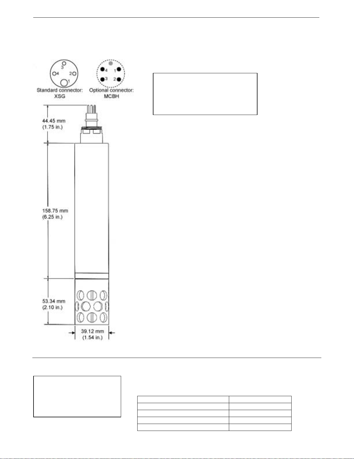
Dimensions and End Cap Connector
The SBE 38 is available with a 4-pin XSG or optional MCBH (wet-pluggable)
external connector.
Pin Signal
1 Common
2 RS-232 Receive or RS-485 A
3 RS-232 Transmit or RS-485 B
4 Power
Baud Rate and Cable Length
Note:
Baud rate is set with the BAUD=
command. See Command
Descriptions in Section 4:
Deploying and Operating RS-232
SBE 38 for command details.
For RS-232, the length of cable that the SBE 38 can drive for transmitting
real-time data is dependent on the baud rate. The allowable combinations are:
Maximum Cable Length (meters) Maximum Baud Rate
800 1200
400 2400
200 4800
100 9600
8
Page 9
Section 3: Preparing SBE 38 for Deployment
Section 3: Preparing SBE 38 for Deployment
This section describes the software installation and the pre-check procedure
for preparing the SBE 38 for deployment.
Installing Software
If not already installed, install SEATERM and other Sea-Bird software
programs on your computer using the supplied software CD:
1. Insert the CD in your CD drive.
2. Double click on Seasoft-Win32.exe.
Note:
It is possible to use the SBE 38
without SEATERM by sending
direct commands from a dumb
terminal or terminal emulator,
such as Windows HyperTerminal.
3. Follow the dialog box directions to install the software.
The default location for the software is c:/Program Files/Sea-Bird. Within that
folder is a sub-directory for each program.
Power and Communications Test
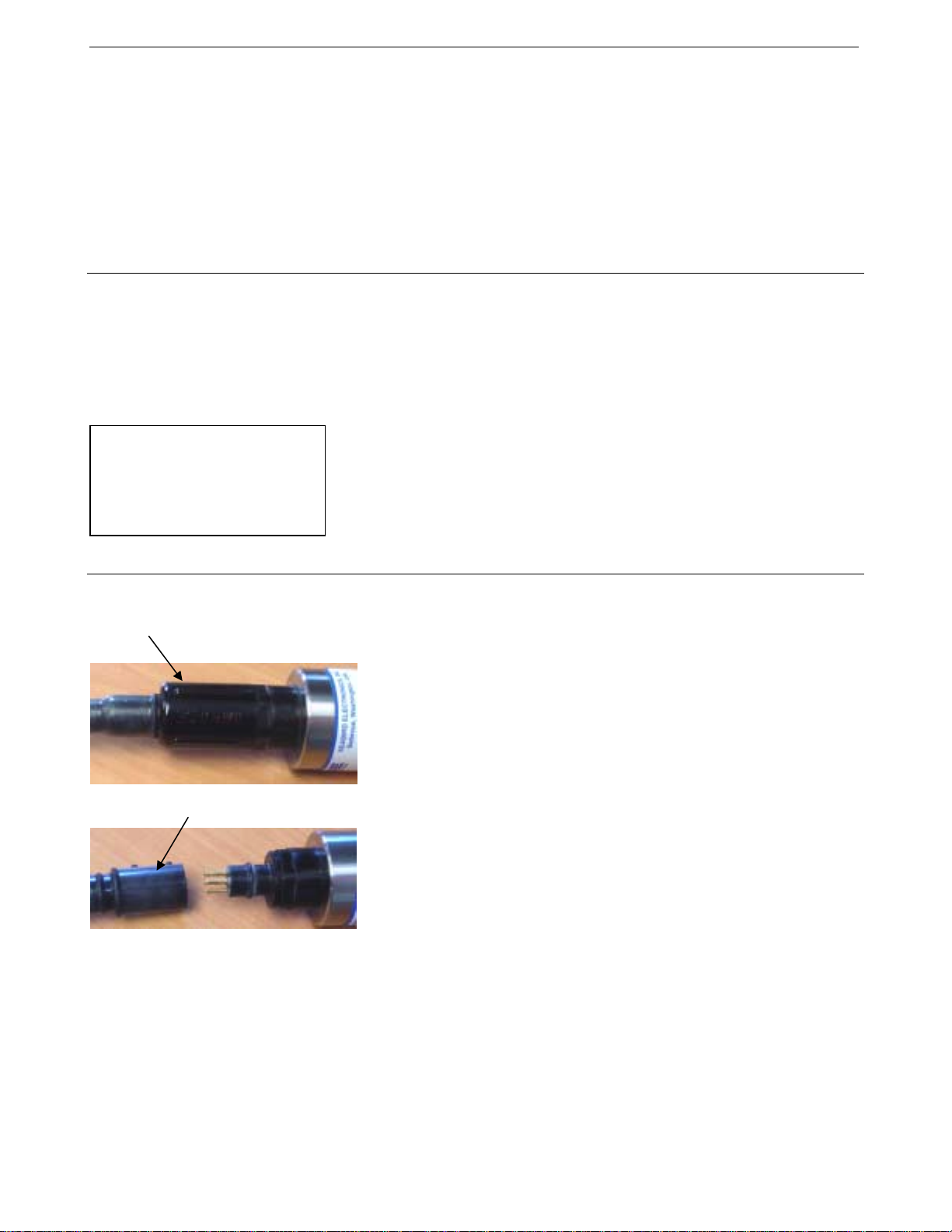
Locking
sleeve
Dummy plug or cable
Test Setup
1. If applicable, remove locking sleeve and dummy plug from bulkhead
2. Install the Sea-Bird I/O cable on the SBE 38:
3. Connect the I/O cable connector to your computer’s serial port.
4. Connect the I/O cable battery terminal clip to a 9-volt battery. Note that
connector:
A. By hand, unscrew the locking sleeve from the SBE 38’s bulkhead
connector. If you must use a wrench or pliers, be careful not to
loosen the bulkhead connector instead of the locking sleeve.
B. Remove the dummy plug from the SBE 38’s bulkhead connector by
pulling the plug firmly away from the connector.
• XSG Connector (shown in photos) - Align the raised bump on the
side of the connector with the large pin (pin 1 - ground) on the
SBE 38.
• MCBH Connector (optional) – Align the pins.
A 25-to-9 pin adapter is supplied for use if your computer has a 9-pin
serial port.
the 9-volt battery supplied with the SBE 38 will provide approximately
50 hours of operation.
9
Page 10

Section 3: Preparing SBE 38 for Deployment
Test
Note:
See SEATERM’s help files for
detailed information on the use
of the program.
1. Double click on SeaTerm.exe. If this is the first time the program is used,
the setup dialog box appears:
Select the instrument type (SBE 38) and the computer COM port for
communication with the SBE 38. Click OK.
2. The main screen looks like this:
Note:
There is at least one way, and as
many as three ways, to enter
a command:
• Manually type a command in
Command/Data Echo Area
• Use a menu to automatically
generate a command
• Use a Toolbar button to
automatically generate
a command
Note:
Once the system is configured and
connected (Steps 3 and 4 below),
to update the Status bar:
• on the Toolbar, click Status; or
• from the Utilities menu, select
Instrument Status.
SEATERM sends the status
command, which displays in the
Command/Data Echo Area, and
updates the Status bar.
Menus
Toolbar
Command/Data Echo Area
Capture
Status bar
Computer
Instrument
Instrument
EPROM version
• Menus – Contains tasks and frequently executed instrument
commands.
• Toolbar – Contains buttons for frequently executed tasks and
instrument commands. All tasks and commands accessed through the
Toolbar are also available in the Menus. To display or hide the
Toolbar, select View Toolbar in the View menu. Grayed out Toolbar
buttons are not applicable.
• Command/Data Echo Area – Echoes a command executed using a
Menu or Toolbar button, as well as the instrument’s response.
Additionally, a command can be manually typed in this area, from the
available commands for the instrument. Note that the instrument must
be awake for it to respond to a command (use the Connect button on
the Toolbar to wake up the instrument).
• Status bar – Provides status information. To display or hide the Status
bar, select View Status bar in the View menu.
COM port
Baud rate, data bits,
stop bits, and parity
10
to file
status –
grayed
out if not
capturing
Page 11

Section 3: Preparing SBE 38 for Deployment
Following are the Toolbar buttons applicable to the SBE 38:
Toolbar
Button
Connect
Status
Re-establish communications with SBE 38.
Computer responds with S> prompt.
Display instrument setup and status (number of
A/D cycles per sample, sampling status, etc.).
Description
Coefficients Display calibration coefficients.
Equivalent
Command*
(press Enter
key)
DS
DC
Capture instrument responses on screen to file.
Capture
File has .cap extension. Press Capture again to
turn off capture. Capture status displays in
—
Status bar.
Free computer COM port used to communicate
Disconnect
with SBE 38. COM port can then be used by
—
another program.
*See Command Descriptions in Section 4: Deploying a nd Oper at i n g
RS-232 SBE 38.
3. In the Configure menu, select SBE 38. The dialog box looks
like this:
Computer COM port, baud rate,
data bits, and parity for
communication between computer
and SBE 38
Note:
SEATERM’s baud rate must be the
same as the SBE 38’s baud rate
(set with BAUD=). BAUD= is factory-
set to 9600, but can be changed by
the user. See Command Descriptions
in Section 4: Deploying and
Operating RS-232 SBE 38 for details.
Interface for communication
between computer and
SBE 38
Make the selections in the Configuration Options dialog box:
• COMM Port: COM 1 through COM 10, as applicable
• Baud Rate: 9600 (documented on front cover of this manual)
• Data Bits: 8
• Parity: None
• Mode: RS-232 (Full Duplex) or RS-485 (Half Duplex)
Click OK to overwrite an existing configuration file, or click Save As to
save the configuration as a new filename.
11
Page 12

Section 3: Preparing SBE 38 for Deployment
4. Click the Connect button on the Toolbar. The display looks like this:
SBE 38 V 1.2 S/N 0090 (this line may not appear)
S>
This shows that correct communications between the computer and the
SBE 38 has been established.
If the system does not provide the S> prompt:
• Click the Connect button again.
• Verify the correct instrument was selected in the Configure menu and
the settings were entered correctly in the Configuration Options
dialog box. Note that the baud rate’s factory setting is documented on
the front cover of this manual.
• Check cabling between the computer and the SBE 38.
5. Display SBE 38 status information by clicking the Status button on the
Note:
See Appendix III: RS-485
Interface for details on sending
commands to an SBE 38 with
optional RS-485 interface.
Toolbar. The display looks like this:
SBE 38 V 1.2 S/N = 0090
NAVG=1
Not sampling data
Automatically start sampling on power up
Default interface is RS-232
6. Command the SBE 38 to take a sample by typing TS and pressing the
Enter key. The display looks like this if the output format was set to
converted data (FORMAT=C) with 4 digits to the right of the decimal
place (DIGITS=4):
23.7658
where 23.7658 = temperature in degrees Celsius
This number should be reasonable; i.e., room temperature.
The SBE 38 is ready for programming and depl oy ment.
12
Page 13

Section 4: Deploying and Operating RS-232 SBE 38
Section 4:
Deploying and Operating RS-232 SBE 38
Note:
See Appendix III: RS-485
Interface for details on deploying
and operating an SBE 38 with
optional RS-485 interface.
Sampling Modes
This section includes a discussion of system operation, example sets of
operation commands, and detailed command descriptions. It also provides
instructions for deploying and recovering the SBE 38.
The SBE 38 has two sampling modes:
• Polled Sampling – take a single sample on command
• Continuous Sampling – sample continuously; start when power is applied
or on command, depending on the setup
Descriptions and examples follow for an SBE 38 with RS-232 Interface. Note
that the SBE 38’s response to each command is not shown in the examples.
Review the sampling modes and the commands described in C ommand
Descriptions before setting up your system.
Polled Sampling
The SBE 38 takes one sample of data on command. Transmission of data to
the computer is dependent on the particular command used.
Example: (user input in bold)
Apply power and establish communications. Set up SBE 38 to average 4 measurements per sample and output
converted data with 3 digits after decimal place. Command SBE 38 to take a sample and send data to computer.
(Apply power and then click Connect on Toolbar.)
S>NAVG=4
S>FORMAT=C
S>DIGITS=3
S>DS (to verify setup)
S>TS
13
Page 14

Section 4: Deploying and Operating RS-232 SBE 38
Continuous Sampling
The SBE 38 continuously samples and transmits real-time data.
Sampling is started by:
• Sending the GO command, or
• Setting AUTORUN=Y. If AUTORUN=Y, sampling automatically starts
when power is applied.
Sampling is stopped by:
• Sending the STOP command, or
• Removing power.
Example: Continuous Sampling (user input in bold)
Example 1 AUTORUN=N: Apply power and establish communications. Set up SBE 38 to average 4 measurements
per sample and output converted data with 3 digits after decimal place. Set up to wait for a command when power is
applied. Remove power.
(Apply power and then click Connect on Toolbar.)
S>NAVG=4
S>FORMAT=C
S>DIGITS=3
S>AUTORUN=N
S>DS (to verify setup)
(Remove power.)
When ready to start sampling, apply power and establish communications. Send command to start sampling
continuously, outputting real-time data. When ready to stop sampling, send command.
(Apply power and then click Connect on Toolbar.)
S>GO
S>STOP (You may need to send command several times to interrupt SBE 38 sampling.)
Example 2 AUTORUN=Y: Apply power and establish communication. Set up SBE 38 to average 4 measurements
per sample and output converted data with 3 digits after decimal place. Set up to automatically begin sampling when
power is applied. Remove power.
(Apply power and then click Connect on Toolbar.)
S>NAVG=4
S>FORMAT=C
S>DIGITS=3
S>AUTORUN=Y
S>DS (to verify setup)
(Remove power.)
To start sampling, apply power. SBE 38 begins sampling continuously, outputting real-time data.
To stop sampling, remove power.
To change setup: apply power, and then stop sampling by command.
(Apply power)
(Press Enter key to get S> prompt)
S>STOP (You may need to send command several times to interrupt SBE 38 sampling.)
(Enter commands as desired to change setup.)
14
Page 15

Section 4: Deploying and Operating RS-232 SBE 38
Command Descriptions
This section describes commands and provides sample outputs.
See Appendix IV: Command Summary for a summarized command list.
When entering commands:
• Input commands to the SBE 38 in upper or lower case letters and register
commands by pressing the Enter key.
• The SBE 38 sends ? CMD if an invalid command is entered.
• If the system does not return an S> prompt after executing a command,
press the Enter key to get the S> prompt.
Note:
If the voltage is below 6.5 volts,
the following displays in
response to the DS command:
WARNING: LOW BATTERY
VOLTAGE!!
Status Command
DS Display status and setup parameters.
Example: (user input in bold).
S>DS
SBE 38 V 1.2 S/N = 0090 (firmware version, serial number)
NAVG=1 (number of A/D cycles to average for each sample [NAVG=])
Not sampling data (sampling status)
Automatically start sampling on power up (sampling start-up mode [AUTORUN=])
Default interface is RS-232 (RS-232 or RS-485 interface [INTERFACE=])
Equivalent to Status button on Toolbar.
Description in example includes, where applicable,
command used to modify parameter.
Note:
The SBE 38’s baud rate (set with
BAUD=) must be the same as
SEATERM’s baud rate (set in
Configure menu).
Note:
After you send AUTORUN=Y, to start
sampling immediately:
• Turn power off and then on again,
or
• Send the GO command.
Setup Commands
INTERFACE=x x=232: Set interface to RS-232.
x=485: Set interface to RS-485. See Appendix III:
RS-485 Interface for all details.
BAUD=x x= baud rate (1200, 2400, 4800, 9600).
Default 9600.
FORMAT=x x=C: Output converted data (°C).
x=R: Output raw data (counts).
DIGITS=x x= number of digits (0 – 6) to rig ht of decimal point
for converted temperature (°C). Applicable only if
FORMAT=C.
NAVG=x x= number of A/D cycles to average per sample
(1 – 127).
Time between samples (seconds)
= (0.133 * NAVG) + 0.339
(Time between samples for continuous sampling;
minimum time required for each polled sample.)
AUTORUN=x x=N: Wait for a command when power is applied.
x=Y: Start continuous sampling automatically when
power is applied.
15
Page 16

Section 4: Deploying and Operating RS-232 SBE 38
Notes:
• To capture real-time data to a file,
do this before starting sampling:
1. Click Toolbar’s Capture button.
2. Enter desired file name in
dialog box. Capture status
displays in status bar at bottom
of screen.
• If the SBE 38 is sampling data and
the voltage is less than 6.5 volts for
ten consecutive scans, the
SBE 38 halts sampling and sets
the status to low battery.
Note:
You may need to send the STOP
command several times to get the
SBE 38 to respond.
Notes:
• Date shown is when calibration
was performed. Calibration
coefficients are initially factory-set
and should agree with Calibration
Certificate shipped with SBE 38.
• See individual Coefficient
Commands below for definitions of
the data in the example.
Sampling Commands
These commands are used to request data from the SBE 38.
For all sampling commands:
• Output format is determined by FORMAT= and DIGITS=.
• Number of A/D cycles per sample is defined by NAVG.
GO Start sampling data continuously, and transmit data
real-time.
Time between samples (seconds)
= (0.133 * NAVG) + 0.339
STOP Stop continuous sampling. Press Enter key to get
S> prompt before entering command.
TS Take 1 sample and transmit data.
TH Take 1 sample and hold data in SBE 38 buffer.
SH Transmit data that was held in SBE 38 buffer.
SL Transmit data from last sample from
SBE 38 buffer.
SLT Transmit data from last sample from SBE 38
buffer, and then take 1 new sample and hold data
in buffer.
Calibration Coefficients Commands
DC Display calibration coefficients. Equivalent to
Coefficients button on Toolbar.
Example: Display coefficients for SBE 38 (user input in bold).
S>DC
SBE 38 V 1.2 S/N = 0090
Cal Date: 08-apr-96
A0 = -9.420702e-05
A1 = 2.937924e-04
A2 = -3.739471e-06
A3 = 1.909551e-07
Note:
F = floating point number
S = string with no spaces
The individual Coefficient Commands listed below modify a particular
coefficient or date:
TCALDATE=S
A0=F
A1=F
S=Temperature calibration date
F=Temperature A0
F=Temperature A1
A2=F F=Temperature A2
A3=F
F=Temperature A3
16
Page 17

Section 4: Deploying and Operating RS-232 SBE 38
Data Output Formats
Notes:
• Each line of output is followed by
a carriage return and line feed.
• For converted data, leading zeros
for temperature output are
suppressed, except for one zero
to the left of the decimal point
(for example, 0.1034).
• See Appendix III: RS-485
Interface for data output format
for an SBE 38 with optional
RS-485 interface.
Converted Data (FORMAT=C)
ttt.ttt
where:
t = temperature (degrees Celsius, ITS-90)
Number of digits to right of decimal point is defined by DIGITS=.
Raw Data (FORMAT=R)
nnnnnn.n
where:
n= counts
Deployment
CAUTION:
Do not use WD-40 or other
petroleum-based lubricants, as
they will damage the connector.
I/O cable
Locking sleeve
1. Install the I/O cable:
A. Lightly lubricate the inside of the cable connector with silicone
grease (DC-4 or equivalent).
B. XSG Connector (shown in photo) - Install the cable connector,
aligning the raised bump on the side of the connector with the large
pin (pin 1 - ground) on the SBE 38. Remove any trapped air by
burping or gently squeezing the connector near the top and moving
your fingers toward the end cap. OR
MCBH Connector (optional) – Install the cable connector,
aligning the pins.
C. Place the locking sleeve over the connector. Tighten the locking
sleeve finger tight only. Do not overtighten the locking sleeve and
do not use a wrench or pliers.
2. Mount the SBE 38.
3. Verify that the hardware and external fittings are secure.
4. Use one of the following sequences to start sampling:
• If AUTORUN=N: Send GO command to start sampling
continuously now, or TS or TH command to take a single sample.
• If AUTORUN=Y: Apply power to start sampling continuously now.
5. Deploy the SBE 38.
Recovery
WARNING!
Pressure housings may flood under
pressure due to dirty or damaged
o-rings or other failed seals, causing
highly compressed air to be trapped
inside. If this happens, a potentially
life-threatening explosion can occur
when SBE 38 is brought to surface.
If the SBE 38 is unresponsive to
commands or shows other signs of
flooding or damage, carefully secure
the SBE 38 in a location away from
people until it has been determined
that abnormal internal pressure
does not exist. Contact Sea-Bird for
assistance with procedures for
safely relieving internal pressure.
1. Use one of the following sequences to stop sampling:
• Press Enter key to get S> prompt, and then send STOP command to
stop sampling continuously. OR
• Remove power.
2. Rinse the SBE 38 with fresh water, and dry thoroughly.
17
Page 18

Section 5: Routine Maintenance and Calibration
Section 5: Routine Maintenance
and Calibration
This section reviews corrosion precautions, connector mating and
maintenance, and sensor calibration. The SBE 38’s accuracy is sustained
by the care and calibration of the sensor and by establishing proper
handling practices.
Corrosion Precautions
All exposed materials are titanium or plastic. No corrosion precautions are
required, but direct electrical connection of the SBE 38 housing to mooring or
other dissimilar metal hardware should be avoided. Rinse the SBE 38 with
fresh water after use and prior to storage.
Connector Mating and Maintenance
Mated connectors do not require periodic disassembly or other attention.
Inspect the connector when it is unmated for signs of corrosion product around
the pins. When remating:
1. Lightly lubricate the inside of the cable connector with silicone grease
CAUTION:
Do not use WD-40 or other
petroleum-based lubricants, as
they will damage the connector.
(DC-4 or equivalent).
2. XSG Connector - Install the cable connector, aligning the raised bump on
the side of the plug/cable connector with the large pin (pin 1 - ground) on
the SBE 38. Remove any trapped air by burping or gently squeezing the
connector near the top and moving your fingers toward the end cap. OR
MCBH Connector (optional) - Install the cable connector, aligning
the pins.
3. Place the locking sleeve over the cable connector. Tighten the locking
sleeve finger tight only. Do not overtighten the locking sleeve and do
not use a wrench or pliers.
Verify that a cable is installed on the SBE 38 before deployment.
18
Page 19

Section 5: Routine Maintenance and Calibration
Sensor Calibration
Sea-Bird sensors are calibrated by subjecting them to known physical
conditions and measuring the sensor responses. Coefficients are then
computed, which may be used with appropriate algorithms to obtain
engineering units. The temperature sensor on the SBE 38 is supplied fully
calibrated, with coefficients printed on the Calibration Certificate (see back of
manual). These coefficients have been stored in the SBE 38’s EEPROM.
We recommend that the SBE 38 be returned to Sea-Bird for calibration.
The primary source of temperature sensor calibration drift is the aging of the
thermistor element. Sensor drift is not substantially dependent upon the
environmental conditions of use, and — unlike platinum or copper elements
— the thermistor is insensitive to shock.
Sea-Bird’s Calibration Methodology
The SBE 38 is calibrated in Sea-Bird’s state-of-the-art calibration laboratory,
which maintains primary temperature standards (water triple point [TPW] and
gallium melting point [GaMP] cells), ITS-90 certified and standards-grade
platinum resistance thermometers, and a low-gradient temperature bath.
Temperature is computed using the Steinhart-Hart polynomial for thermistors
(Steinhart and Hart, 1968; Bennett, 1972), which is based on thermistor
physics. The equation characterizes the non-linear temperature versus
resistance response of the sensor. Note that thermistors require individualized
coefficients to the Steinhart-Hart equation, because the thermistor material is
an individualized mix of dopants:
t90 = 1.0
a0 + a1 * [ln(n)] + a2 * [ln
2
(n)] + a3 * [ln
where
n = SBE 38 raw output (counts).
3
(n)]
- 273.15 [°C]
19
Page 20

Glossary
Glossary
PCB – Printed Circuit Board.
SBE 38 – High-accuracy digital oceanographic thermometer.
SBE Data Processing – Sea-Bird’s Win 95/98/NT/2000/XP data
processing software, which calculates and plots measured and
derived variables. SBE Data Processing can be used to view and process the
entire data stream, including data from the SBE 38, when the SBE 38 is
integrated with the SBE 21 or 45 thermosalinograph.
Scan – One data sample.
SEASAVE – Sea-Bird’s Win 95/98/NT/2000/XP software used to acquire,
convert, and display real-time or archived raw data. SEASAVE can be used to
view and process the entire data stream, including data from the SBE 38, when
the SBE 38 is integrated with the SBE 21 or 45 thermosalinograph.
SEASOFT-DOS – Sea-Bird’s complete DOS software package, which
includes software for communication, real-time data acquisition, and data
analysis and display.
SEASOFT-Win32 – Sea-Bird’s complete Win 95/98/NT/2000/XP software
package, which includes software for communication, real-time data
acquisition, and data analysis and display. SEASOFT-Win32 includes
SEATERM, SeatermAF, SEASAVE, SBE Data Processing, and Plot39.
SEATERM – Sea-Bird’s Win 95/98/NT/2000/XP terminal program used to
communicate with the SBE 38.
20
Page 21

Appendix I: Functional Description
Appendix I: Functional Description
Sensor Interface
Temperature is acquired by applying an AC excitation to a hermetically sealed
VISHAY reference resistor and an ultra-stable aged thermistor with a drift rate
of less than 0.002°C per year. A 24-bit A/D converter digitizes the outputs of
the reference resistor and thermistor. AC excitation and ratiometric
comparison using a common processing channel avoids errors caused by
parasitic thermocouples, offset voltages, leakage currents, and reference errors.
Maximum power dissipated in the thermistor is 0.5 microwatts, and
contributes less than 200 µK of overheat error.
A raw count (ratio) is related to resistance measurements:
raw counts = 1048576 * (NT) / (NR)
where
NR = output from reference resistor
NT = thermistor output
The SBE 38’s output is computed from the raw count and the calibration
coefficients that are stored in EEPROM.
The number of acquisition cycles (raw counts) averaged per measurement is
user-programmable (NAVG= command; see Section 4: Deploying and
Operating RS-232 SBE 38). Increasing the number of cycles per measurement
increases the time to acquire the measurement and the interval between
measurements, while reducing the RMS temperature noise from the sensor.
The interval between measurements is:
interval [seconds] = (0.133 * NAVG) + 0.339
where
NAVG = number of acquisition cycles per measurement
Settings
Calibration coefficients and setup parameters (BAUD=, NAVG=,
INTERFACE=, etc.) are written to EEPROM and are non-volatile. These
settings do not change if power is removed.
21
Page 22

Appendix II: ?
Appendix II: Electronics Disassembly/Reassembly
1. Remove the titanium end cap and electronics from the housing as follows:
A. Wipe the outside of the end cap and housing dry, being careful to
remove any water at the seam between them.
B. Unscrew the end cap.
C. Pull the end cap and attached electronics out of the housing. Note that
the PCB is electrically connected to the I/O connector.
Note:
Before delivery, a desiccant bag is
placed in the housing, and the
electronics chamber is filled with dry
Argon gas. These measures help
prevent condensation.
To ensure proper functioning:
1. Install a new desiccant bag
each time you open the
housing. If a new bag is not
available, see Application
Note 71: Desiccant Use and
Regeneration (drying).
2. If possible, dry gas backfill each
time you open the housing. If you
cannot, wait at least 24 hours
before redeploying, to allow the
desiccant to remove any moisture
from the chamber.
D. Remove any water from the end cap O-ring and mating surfaces
inside the housing with a lint-free cloth or tissue.
E. Be careful to protect the O-ring from damage or contamination.
2. Reinstall the end cap and electronics in the housing as follows:
A. Remove any water from the O-ring and mating surfaces in the
housing with a lint-free cloth or tissue. Inspect the O-ring and mating
surfaces for dirt, nicks, and cuts. Clean as necessary. Apply a light
coat of O-ring lubricant (Parker Super O Lube) to O-ring and
mating surfaces.
B. Carefully fit the electronics into the housing.
C. Screw the end cap into the housing.
End cap
O-ring
22
Page 23

Appendix III: RS-485 Interface
Appendix III: RS-485 Interface
Operation Description
Commands can be directed to one SBE 38 or globally to all SBE 38s. If
IDREQ=Y, a command prefix (#ii) is used to direct commands to an SBE 38
with the same ID (ii = ID). Global commands do not use a prefix, regardless of
the setting for IDREQ=, and are recognized by all SBE 38s attached to the
RS-485 interface.
An example follows for a system with two SBE 38s (IDs 01 and 02)
online. Note that the SBE 38’s response to each command is not shown
in the example. Review the commands described in Command Descriptions
and the example below before setting up your system.
Example: Wake up all SBE 38s. Set up all SBE 38s to average 4 measurements per sample and output converted
data with 3 digits to the right of the decimal place. Command all SBE 38s to take a sample and hold data in
buffer, and then command each SBE 38 to transmit data from buffer. Repeat sampling sequence a number of
times. (user input in bold)
(Apply power and click Connect on Toolbar to wake up all SBE 38s.)
S>IDREQ=Y (global command to require ID prefix)
S>#01NAVG=4 (set number of measurements per sample to 4 for SBE 38 with ID=01)
S>#02NAVG=4 (set number of measurements per sample to 4 for SBE 38 with ID=02)
S>#01FORMAT=C (set output format to converted data for SBE 38 with ID=01)
S>#02FORMAT=C (set output format to converted data for SBE 38 with ID=02)
S>#01DIGITS=3 (set number of digits to right of decimal point to 3 for SBE 38 with ID=01)
S>#02DIGITS=3 (set number of digits to right of decimal point to 3 for SBE 38 with ID=02)
S>#01DS (verify setup with status command for SBE 38 with ID=01)
S>#02DS (verify setup with status command for SBE 38 with ID=02)
S>GDATA (global command to all SBE 38s to take sample and hold data in buffer)
S>DATA01 (get data from buffer of SBE 38 with ID=01)
S>DATA02 (get data from buffer of SBE 38 with ID=02)
(Repeat GDATA through DATA02 commands as desired)
23
Page 24

Appendix III: RS-485 Interface
Command Descriptions
RS-485 Commands
Note:
For reliable operation, all commands
may need to be preceded with two @
characters to clear the buffers.
Example (status command for
SBE 38 with ID=01):
S>@@#01DS
Example 1: Multiple RS-485 instruments on 1 pair of wires (user input in bold)
S>IDREQ=Y (global command to require ID prefix)
S>#01NAVG=4 (set number of A/D cycles to average for SBE 38 with ID=01)
S>#02NAVG=4 (set number of A/D cycles to average for SBE 38 with ID=02)
S>#01DS (verify setup with status command for SBE 38 with ID=01)
S>#02DS (verify setup with status command for SBE 38 with ID=02)
Example 2: Only 1 SBE 38 on 1 pair of wires (user input in bold)
S>IDREQ=N (global command to require ID prefix)
S>NAVG=4 (set number of A/D cycles to average for SBE 38, no ID required as part of command)
S>DS (verify setup with status command for SBE 38, no ID required as part of command)
Global Commands
Global commands are recognized by all SBE 38s attached to the
RS-485 interface.
IDREQ=x x=Y: Precede commands to individual SBE 38s
with #ii, where ii= ID (ii = 0 -99). Use this setting
for systems with multiple RS-485 instruments on
1 pair of wires. Note that the use of a prefix does
not apply to Global, Get Data, or ID commands.
x=N: Do not precede commands to individual
SBE 38s with #ii. Use this setting for systems with
only 1 SBE 38.
Note:
GDATA and ADATA perform the
same function in the SBE 38.
Both are included here to provide
compatibility with RS-485 MicroCATs.
TXDELAY=x x= delay after SBE 38 transmits a reply until
SBE 38 transmitter is disabled
(1 – 500 milliseconds). Default 25 milliseconds.
RXDELAY=x x= delay after SBE 38 receives a command
until SBE 38 transmitter is enabled
(1 – 500 milliseconds). Default 25 milliseconds.
GDATA Command all SBE 38s to take 1 sample and hold
data in SBE 38 buffer until receiving:
DATAii;
SH, SL, or SLT (if IDREQ=N); or
#iiSH, #iiSL, or #iiSLT (if IDREQ=Y).
ADATA Command all SBE 38s to take 1 sample and hold
data in SBE 38 buffer until receiving:
DATAii;
SH, SL, or SLT (if IDREQ=N); or
#iiSH, #iiSL, or #iiSLT (if IDREQ=Y).
Get Data Command
DATAii Get data obtained with GDATA or ADATA
command from SBE 38 with ID = ii (ii = 0 -99).
24
Page 25

Appendix III: RS-485 Interface
ID Commands
Only one SBE 38 can be online when sending these commands.
ID? Display SBE 38 ID (ID = ii, where ii= 0-99) and
whether ID is required as a prefix for commands to
individual SBE 38s (see IDREQ= command).
*ID=ii Set SBE 38 ID to ii, where ii= 0-99. This command
must be sent twice, because the computer requests
verification. If more than one RS-485 instrument
is online when sending this command, all
instruments online will be set to same ID.
All Other Commands
All other commands (status, setup, sampling, and coefficients) are listed
in Section 4: Deploying and Operating RS - 23 2 SBE 38 and in
Appendix IV: Command Summary.
Notes on use of these commands for an SBE 38 with RS-485 interface:
• Effect of IDREQ= command:
If IDREQ=Y, precede these commands with #ii (ii = 0 – 99) to direct a
command to a particular SBE 38.
If IDREQ=N, do not precede these commands with #ii. This setting
works only for a system with one SBE 38.
• The RS-485 interface cannot accommodate multiple instruments
transmitting real-time data at the same time. Therefore, do not set
AUTORUN=Y (start sampling continuously when power is applied) for a
system with more than one RS-485 instrument on a pair of wires.
Similarly, do not attempt to send the GO command to multiple SBE 38s
on a pair of wires, as the system cannot transmit a command to one
instrument while another instrument is transmitting real-time data.
• If AUTORUN=Y (sample continuously when power is applied), set
NAVG= (A/D cycles to average per sample) to a value greater than 30.
Data Output Formats
Notes:
• Each line of output is followed by
a carriage return and line feed.
• For converted data, leading zeros
for temperature output are
suppressed, except for one zero
to the left of the decimal point
(for example, 0.1034).
Converted Data (FORMAT=C)
Output from continuous sampling: ttt.ttt
Output from DATAii, #iiTS, TS, #iiSH, SH, #iiSL, SL, #iiSLT,
or SLT command: ii, sssss, ttt.ttt
where:
! t = temperature (°C, ITS-90)
(number of digits to right of decimal point is defined by DIGITS=)
! ii = ID (0 – 99)
! sssss = SBE 38 serial number
Raw Data (FORMAT=R)
nnnnnn.n
where:
n = counts
25
Page 26

Appendix III: RS-485 Interface
Wiring
The MAX1483 transceivers used in the SBE 38 are designed for bi-directional
data communications on multi-point bus transmission lines. To minimize
reflections, terminate the line at both ends in its characteristic impedance.
Also, keep stub lengths off the main line as short as possible (although the slewrate-limited MAX1483 is more tolerant of imperfect termination than standard
RS-485 ICs).
Optional
RS-485
terminating
resistor
solder
points
Conversion of RS-232 to RS-485 or RS-485 to RS-232
Sea-Bird supplies the SBE 38 with the correct wiring from the I/O connector
Notes:
• See Appendix II: Electronics
Disassembly / Reassembly to
access the PCB.
• Send the INTERFACE=232 or
INTERFACE=485 command to
program the SBE 38 to match the
wired configuration.
to the Printed Circuit Board (PCB) for your ordered configuration (standard
RS-232 or optional RS-485). If desired, you can modify the wiring to change
the configuration:
For RS-485 interface, connect:
• Pin 2 (black) to A
• Pin 3 (green) to B
For RS-232 interface, connect:
• Pin 2 (black) to RX
• Pin 3 (green) to TX
For RS-232 interface
For RS-485 interface
26
Page 27

Appendix IV: Command Summary
Appendix IV: Command Summary
CATEGORY COMMAND DESCRIPTION
Notes:
• See Command
Descriptions in Section 4:
Deploying and Operating
RS-232 SBE 38 for detailed
information and examples.
• See Appendix III:
RS-485 Interface for
RS-485 commands.
Status DS
INTERFACE=x
BAUD=x
FORMAT=x
Setup
DIGITS=x
NAVG=x
AUTORUN=x
GO
STOP
TS
Sampling
TH
SH
SL
SLT
Coefficients
(F=floating point
number; S=string
with no spaces)
Date shown is
when calibration
was performed.
Calibration
coefficients are
initially factory-set
and should agree
with Calibration
Certificate shipped
with SBE 38.
DC
CALDATE=S
A0=F
A1=F
A2=F
A3=F
Display status and setup parameters.
x=232: RS-232 interface.
x=485: RS-485 interface.
x= baud rate (1200, 2400, 4800, 9600,
19200, 38400). Default 9600.
x=C: Output converted data (°C).
x=R: Output raw data (counts).
x= number of digits (0 – 6) to right of
decimal point for converted
temperature (°C). Applicable only if
FORMAT=C
x= A/D cycles to average per sample
(1 – 127).
x=N: Wait for a command when
power applied.
x=Y: Start continuous sampling
automatically when power applied.
Start continuous sampling now.
Stop continuous sampling.
Press Enter key to get S> prompt
before entering command.
Take 1 sample and transmit data.
Take 1 sample and hold data in buffer.
Transmit data that was held in buffer.
Transmit data from last sample from
buffer.
Transmit data from last sample from
buffer, and then take 1 new sample and
hold data in buffer.
Display calibration coefficients; all
coefficients and dates listed below are
included. Use individual commands
below to modify a particular
coefficient or date.
S=Temperature calibration date.
F=Temperature A0.
F=Temperature A1.
F=Temperature A2.
F=Temperature A3.
27
Page 28

Appendix IV: Replacement Parts
Appendix V: Replacement Parts
Part
Number
231361
30931
801093
801206
17130 25-pin to 9-pin adapter
17046 4-pin dummy plug For SBE 38 (XSG) connector 1
17043
171398 4-pin dummy plug
171192
O-ring, Parker 2-214
25-pin DB-25S I/O cable
9-pin DB-9S I/O cable
I/O connector/dummy plug
I/O connector/dummy plug
Part Application Description
Plastic temperature
sensor guard
N674-70
4-pin RMG-4FS to
with battery snap,
2.4 m (8 ft) long
4-pin MCIL4FS to
with battery snap,
2.4 m (8 ft) long
locking sleeve
locking sleeve
Screws to end cap to protect
temperature sensor
Placed in end cap groove for
watertight seal
From SBE 38 (XSG) to computer 1
From SBE 38 (wet-pluggable) to
computer
Connects I/O cable to 9-pin COM
port on computer
For use with 17046 1
For SBE 38 (wet-pluggable)
connector
For use with 171398 1
Quantity in
SBE 38
1
1
1
1
1
28
Page 29

Index
Index
A
About Sea-Bird · 4
B
Baud rate · 8
C
Cable length · 8
Calibration · 19
Command summary · 27
Commands
coefficients · 16
descriptions · 15
get data · 24
global · 24
ID · 25
RS-485 · 24
sampling · 16
setup · 15
status · 15
Communication defaults · 11
Connector · 8, 18
Continuous sampling · 14
Corrosion precautions · 18
D
Data output formats · 17, 25
Deployment
installation · 17
preparing for · 9
Description · 6
Desiccant · 22
Dimensions · 8
Disassembly / reassembly · 22
E
Electronics · 22
F
Format
data output · 17, 25
Functional description · 21
M
Maintenance · 18
Modes · See Sampling modes
O
Operation description · 23
P
Parts
replacement · 28
Polled sampling · 13
Q
Quick start · 4
R
Recovery
physical handling · 17
Replacement parts · 28
RS-232 · 13
conversion to RS-485 · 26
RS-485 · 23
conversion to RS-232 · 26
wiring · 26
S
Sampling modes · 13
continuous · 14
polled · 13
SBE Data Processing · 6
SEASAVE · 6
SEASOFT-DOS · 6
SEASOFT-Win32 · 6, 9
SEATERM · 6, 9, 10
main screen · 10
toolbar buttons · 11
Sensor · 7
Settings · 21
Software · 6
installation · 9
Specifications · 7
System description · 6
G
Glossary · 20
L
Limited liability statement · 2
T
Testing · 9
U
Unpacking SBE 38 · 5
29
 Loading...