

Page 1
1
Release date 10
SBE 37-IMP-ODO
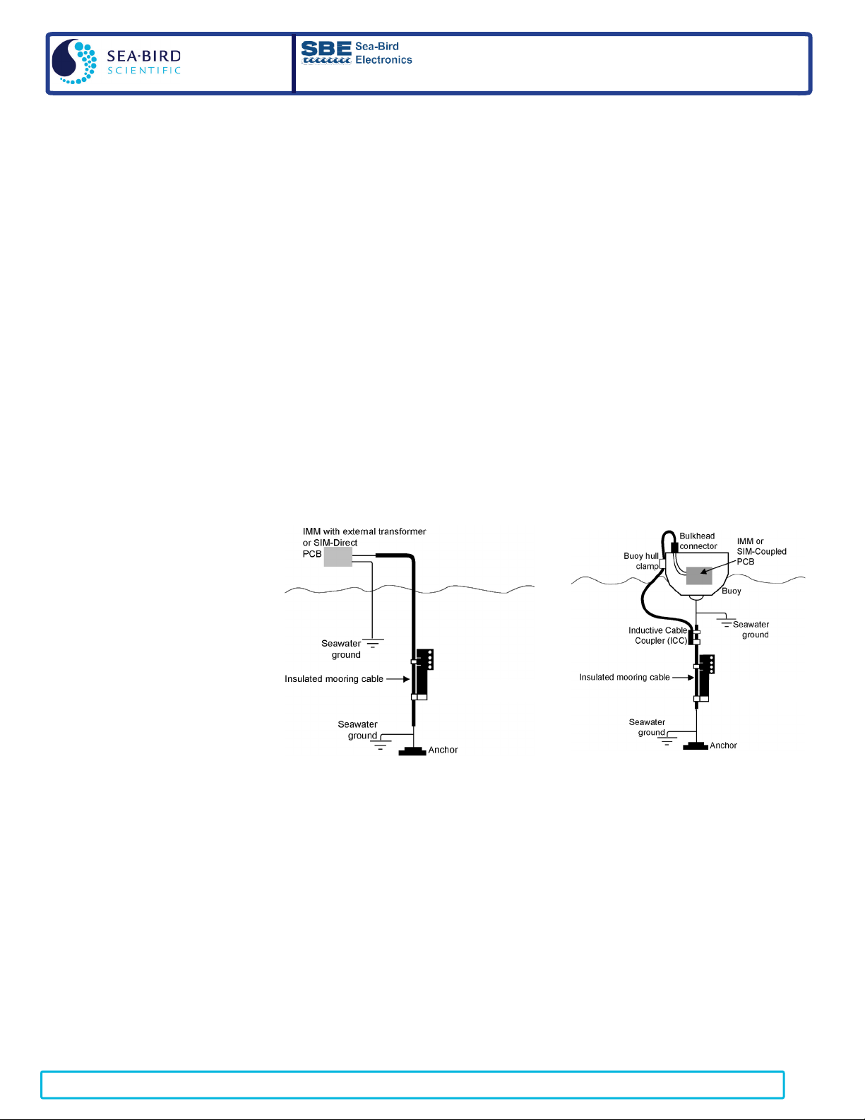
Direct Connection
SBE 37-IMP-ODO
Connection with Inductive Cable Coupler (ICC)
SBE 37-IMP-ODO MicroCAT Recorder
Reference
Sheet
(see User Manual for complete details)
Sampling Modes
• Polled – On command, wake up, run pump, take one sample, transmit data, and go to sleep.
• Autonomous – At pre-programmed intervals, wake up, run pump, sample, store data in FLASH memory, and go to sleep.
• Combo – On command, transmit last Autonomous sampling data.
• Averaging – On command, calculate and transmit average of Autonomous sampling data since last request.
Setup
1. Install AA lithium cells (Note: ODO MicroCATs use a battery pack with a yellow cover plate):
A. Remove modem end cap: Wipe dry housing/end cap seam. Remove 2 cap screws from end cap, and twist end cap counterclockwise. Pull end
cap out. Disconnect Molex connecting to battery pack. Wipe O-ring mating surfaces in housing with lint-free cloth.
B. Remove battery pack and install cells: Loosen captured screw in battery pack cover. Use handle to lift battery pack out of housing. Keep
handle upright. Unscrew yellow cover plate from top of battery pack assembly. Roll 2 O-rings on side of battery pack out of grooves. Insert
cells into battery pack, and roll 2 O-rings into grooves on side of battery pack. Align pin on battery cover plate PCB with post hole, keep
handle upright, and screw yellow cover plate onto battery pack assembly.
C. Reinstall battery pack and modem end cap: Align D-shaped opening and pins on shaft. Lower battery pack into housing; push gently to mate.
Tighten captured screw to secure battery pack in housing. Remove water from O-rings and mating surfaces with lint-free cloth. Inspect Orings and mating surfaces for dirt, nicks, and cuts. Clean as necessary. Apply light coat of O-ring lubricant to O-ring and mating surfaces.
Plug Molex connector together. Fit end cap into housing. Reinstall 2 cap screws.
2. Double click on SeatermV2.exe. In Instruments menu, select SBE 37 IM. SeatermIM opens.
3. In Communications menu, select Configure. In dialog box. Input Comm port and baud rate. Set ID to Automatically get ID for
1 MicroCAT on line; set ID to Use fixed ID for multiple MicroCATs on line. Click OK.
4. SeatermIM automatically connects to MicroCAT. As it connects, it sends #iiGetHD and displays response, and then fills Send Commands
window with list of commands for your MicroCAT.
5. Ensure all data has been uploaded from memory, and then send #iiInitLogging to make entire memory available for recording.
If #iiInitLogging is not sent, data will be stored after last recorded sample.
6. Set Date and Time (#iiDateTime=).
7. Set up other parameters as desired — see Command Instructions and Command List.
Deployment
1. Attach MicroCAT to insulated
mooring cable with Sea-Bird
mounting brackets. MicroCAT is
intended for deployment with the
sensors at the top for proper
operation – see manual for details.
Install (optional) ICC on mooring
cable.
2. See MicroCAT manual for SIM
wiring and configuration; see IMM
manual for IMM wiring and
configuration.
Data Upload
1. Connect cable from MicroCAT to computer.
2. Double click on SeatermV2.exe. SeatermV2 opens; in Instruments menu, select SBE 37 IM. SeatermIM opens.
3. In Communications menu, select Configure. In dialog box, select Comm port and baud rate (factory set to 9600). Set ID to Automatically get ID
for 1 MicroCAT on line; set ID to Use fixed ID for multiple MicroCATs on line. Click OK.
4. SeatermIM automatically connects to MicroCAT. As it connects, it sends #iiGetHD and displays response, and then fills Send Commands
window with list of commands for your MicroCAT.
5. If sampling autonomously (logging), command MicroCAT to stop logging by sending #iiStop.
6. Click Upload menu to upload stored data.
7. SeatermIM prompts you to run SBE Data Processing to convert uploaded .hex file to .cnv file for use by other modules in data processing
software. Process file and review data to ensure all data has been uploaded.
Command Instructions
• Input commands in upper or lower case letters and register commands by pressing Enter key.
• MicroCAT sends an error message if invalid command is entered.
• If new command is not received within 2 minutes after completion of a command, MicroCAT returns to quiescent (sleep) state.
• If in quiescent (sleep) state, re-establish communications by selecting Connect in SeatermIM’s Communications menu.
-28-15, Reference sheet version 007; Digital Firmware version 2.13.0 & later; IMM Firmware version 1.10 & later
Page 2

2
Release date 10
Command List (commands most commonly used in field; see manual for complete list and detailed descriptions)
FUNCTION
CATEGORY
COMMAND
DESCRIPTION
PwrOn
Send wakeup tone to all IMs.
PwrOff
Send power off command to all IMs. Logging and memory retention unaffected.
AutoPwrOn=x
x=Y: Send PwrOn to IMs when power applied to SIM. x=N: Do not.
Status
DS
Display SIM firmware version and status.
Baud=x
x= baud from SIM to computer (1200, 2400, 4800, or 9600). Default 9600.
DataNNMax=x
x= timeout that applies to Dataii; default 1000 millisec.
RelayMax=x
x= timeout that applies to all other commands; default 20 sec.
EchoOn
Echo characters received from computer.
EchoOff
Do not echo characters received from computer.
ID and
Numbe r
ID?
Get MicroCAT ID (0-99).
*ID=ii
Set ID to ii (ii=0-99). Only 1 MicroCAT can be on line. Must be sent twice.
!iiSetGroupNumber=x
Set MicroCAT group number (0–9). Group 0 pre-defined as all instruments with integrated IMM.
!iiGetCD
Get integrated IMM configuration data.
!iiGetHD
Get integrated IMM hardware data.
!iiGetSD
Get integrated IMM status data.
Testing
!iiTestCableCoupler
Test integrity of integrated IMM. Line must be captured before command sent
!iiSetGDataStr=x
x= character string to send to MicroCAT when GData is sent from surface IMM/SIM.
GData
Send string defined by !iiSetGDataStr=; hold response until!iiData, Dataii, or !iiGetReply sent.
!iiData, Dataii, or !iiGetReply
Get data obtained with GData from MicroCAT with ID=ii.
#iiGetCD (get configuration data), #iiGetSD (get status data), #iiGetCC (get calibration coefficients), #iiGetEC (get event counter
data), #iiResetEC (reset event counter), #iiGetHD (get hardware data), #iiDS (get status), #iiDC (get calibration coefficients)
#iiDateTime=mmddyyyyhhmmss
Set real-time clock month day year hour minute second.
#iiBaudRate=x
x= baud (4800, 9600, 19200, 38400, 57600, 115200) for Serial Mode (internal RS-232 connector).
#iiOutputExecutedTag=x
x=Y: Output XML Executed and Executing tags. x=N: Do not.
#iiReferencePressure=x
x = reference pressure (decibars) (for MicroCAT without pressure sensor).
QS
Place MicroCAT in quiescent (sleep) state; for use in Serial mode only.
#iiMinCondFreq=x
x= minimum conductivity frequency (Hz) to enable pump turn-on.
#iiAdaptivePumpControl=x
x=Y: Use Adaptive Pump Control. x=N: Run pump for [#iiOxNTau * #iiOxTau20].
#iiOxNTau=x
x= pump time multiplier. Range 0 – 100.0; default 7.0.
#iiPumpOn #iiPumpOff
Turn pump on or off, for testing.
SBE 63 DO
Sensor Setup
#iiSend63=command
Command MicroCAT to send command to SBE 63 and receive response.
Other commands
Required: SetEcho=1, SetFormat=1, SetAvg=1 to 16 (recommend 2), SetAutoRun=0.
Memory
Setup
#iiInitLogging
Initialize logging, setting memory pointer to 0.
#iiSampleNumber=x
x= sample number for first sample when logging begins.
x=0: Output raw decimal data.
x=5: Output converted decimal data, compatible mode.
#iiOutputTemp=x
x=Y: Output temperature. x=N: Do not.
#iiSetTempUnits=x
x=0: Temperature °C, ITS-90. x=1: Temperature °F, ITS-90.
#iiOutputCond=x
x=Y: Output conductivity. x=N: Do not.
#iiSetCondUnits=x
Conductivity, specific conductivity units. x=0: S/m. x=1: mS/cm. x=2: µS/cm.
#iiOutputPress=x
x=Y: Output pressure. x=N: Do not.
#iiSetPressUnits=x
x=0: Pressure decibars. x=1: Pressure psi (gauge).
#iiOutputOx=x
x=Y: Output oxygen. x=N: Do not.
#iiSetOxUnits=x
x=0: Oxygen ml/L. x=1: Oxygen mg/L.
#iiOutputSal=x
x=Y: calculate and output salinity (psu). x=N: do not.
#iiOutputSV=x
x=Y: calculate and output sound velocity (m/s). x=N: do not.
#iiOutputSC=x
x=Y: calculate and output specific conductivity. x=N: do not.
#iiTxSampleNum=x
x=Y: Output sample number with data. x=N: Do not.
#iiSampleInterval=x
x = interval between samples (10 – 21,600 sec).
#iiStartNow
Start logging now. Data stored in FLASH memory.
#iiStartDateTime=mmddyyyyhhmmss
Delayed logging start: month day year hour minute second.
#iiStartLater
Start logging at delayed start time. Data stored in FLASH memory.
#iiStop
Stop logging or waiting to log.
(data not stored
#iiTS
(Do not run pump) Take sample, output data.
#iiTPS
Run pump, take sample, output data.
#iiTPSH
Run pump, take sample, do not output data.
#iiTPSS
Run pump, take sample, store in FLASH me mory, output data.
#iiTSN:x
(Do not run pump) Take x samples and output data.
#iiTPSN:x
Run pump continuously while taking x samples, output data.
#iiT63
Do not pump. Take sample from SBE 63, output oxygen in format set by SetFormat= in SBE 63.
#iiSL
Output last sample.
#iiSLTP
Output data from last sample, then run pump and take new sample.
#iiSLTPR
Output raw data from last sample, then run pump and take new sample.
#iiDNx
Upload last x scans from memory; can send while logging
#iiGetSamples:b,e
Upload scan b to e, in #iiOutputFormat. Send #iiStop before sending.
#iiDDb,e
Upload scan b to e, converted decimal format Send #iiStop before sending.
Power-On
SIM
Commands
Communications
MicroCAT
Integrated
IMM
Commands
(ii =
MicroCAT
ID)
See IMM
manual for
details
Group
Status
Get Data
Status
General
Setup
Pump
Setup
#iiOutputFormat=x
x=1: Output converted decimal data.
x=4: Output converted decimal data, alternate.
MicroCAT
Acquisition
controller
Commands
MicroCAT
Micro-
(ii =
ID)
Output
Format
Setup
Autonomous
Sampling
(logging)
Polled
Sampling
in FLASH
memory unless
noted; format
specified by
#iiOutput
Format=
unless noted)
Data Upload
-28-15, Reference sheet version 007; Digital Firmware version 2.13.0 & later; IMM Firmware version 1.10 & later
 Loading...