


Deutsch
Montage- und Bedienungsanleitung Typ AWD1D5
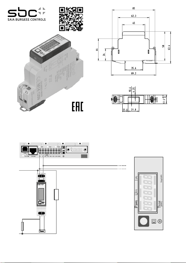
32 A-Wirkenergiezähler 1-phasig mit Stromwandler und S-Bus, Pic. 1
Beschreibung
Energiezähler mit integrierter S-Bus Schnittstelle ermöglichen das Auslesen aller relevanten Daten wie Zählerstand,
Strom, Spannung, Leistung (aktiv und reaktiv) und cos phi.
Technische Daten
Anschlussbild ■ Pic. 2
Abmessungen ■ Pic. 3
Genauigkeitsklasse ■ B gemäss EN50470-3,
1 gemäss IEC62053-21
Referenz-, ■ Iref = 5 A, Imax = 6 A, Ist = 10 mA
Maximal-, Anlaufstrom
Betriebsspannung ■ 230 VAC, 50 Hz
Toleranz −20%/+15%
Zählbereich ■ 000'000,0…9'999'999 kWh
Anschlüsse ■ Leiterquerschnitt max. 6 mm2,
Hauptstromkrei s Schraubendreher Pozi Nr. 1, Schlitz
Nr. 1, Anzugsmoment 1,2 Nm
Anschlüsse ■ Leiterquerschnitt max. 2,5 mm2,
Steuerstromkrei s Schraubendreher Pozi Nr. 0, Schlitz
Nr. 1, Anzugsmoment 0,5 Nm
Betriebstemperatur ■ −25… +55 °C (nicht konden-
Umgebungs- ■ Mechanische M2
bedingungen Elektromagnetische E2
sierend gemäss Norm EN50470)
Anzeigeelemente (Pic. 4)
T total (kWh) ■ Zeigt den Verbrauch Total
CT ■ Zeigt das eingestellte
P (kW) ■ Zeigt die momentane Leistung
U (V) ■ Zeigt die Spannung
I (A) ■ Zeigt den Strom
10 Imp/kWh ■ Pulsiert entsprechend der
Stromwandlerverhältnis
bezogenen Leistung. Bei Fehler
(Anschlüsse 1L/2L vertauscht)
pulsiert das Segment mit
600/600 ms.
Hinweise vor dem Anschliessen
Um Feuchtigkeit im Zähler durch Kondenswasser zu vermeiden, den Zähler vor dem Anschliessen ca. eine halbe
Stunde bei Raumtemperatur akklimatisieren.
Achtung!
Diese Geräte dürfen nur durch eine Elektrofachkraft
installiert werden, andernfalls besteht Brandgefahr oder
Gefahr eines elektrischen Schlages!
Anschlussschema
Der sekundär, netzseitige Stromwandleranschluss ist mit der zu messenden Phase zu
verbinden und der Stromwandler darf aus
diesem Grund nicht geerdet werden.
Diese Verbindung ist den lokalen Installationsvorschriften
entsprechend abzusichern.
Bedienung der LCD-Anzeige
Siehe Seite mit LCD-Menüführung.
Montagehinweis
Die Energiezähler lassen sich auf eine 35 mm Schiene
(EN60715TH35) aufschnappen. Sie dürfen nur in dazu
geeigneten Installationsschränken verwendet werden.
EG-Konformitätserklärung
Wir, Saia-Burgess Controls AG, CH 3280 Murten (Schweiz),
erklären in alleiniger Verantwortung, dass die Energiezählerprodukte:
■ AWD1D5GS00A3A00 (50:5)
■ AWD1D5FS00A3A00 (100:5)
auf die sich die Erklärung bezieht, mit der Richtlinie
2004/22/EG und den folgenden Normen oder normativen
Dokumenten übereinstimmen:
■ EN50470 Teile 1 und 3 (Elektronische Zähler),
Oktober 2006.
ESD auf Apparateseite: 13 kV.
Murten, 30.04.2013
Konformitätsbewertungsstelle:
METAS-Cert, Nr. 1259
CH-3003 Bern-Wabern
Gezeichnet: Urs Tanner, Site Quality Leader
4 319 5143 0d 06.2015 Änderungen technischer Daten vorbehalten

Deutsch
Technische Daten S-Bus
Bus System S-Bus
Übertragunsraten 4800-9600-19'200-38'400-57'600-115'200.
Die Übertragungsrate wird automatisch erkannt
Übertragungsmodus Data
Bus Länge (max.) 1200 m (ohne Repeater)
Reaktionszeit: Schreiben: bis 60 ms
Lesen: bis 60 ms
■ Die Kommunikation ist 30 s nach Einschalten bereit.
■ Energiezähler in einem Bussystem mit hohem Datenaufkommen können zu Leistungseinbussen auf dem Bus führen.
■ Die Daten werden alle 5 s aktualisiert, aus diesem Grund sollte der Abfrageintervall eines Energiezählers nicht kürzer
als 5 s sein.
■ 254 Geräte können am S-Bus angeschlossen werden. Bei mehr als 128 Geräten sollte ein Repeater benutzt werden.
■ Die Schnittstelle hat keinen Abschlusswiderstand, dieser sollte extern bereitgestellt werden.
■ Die verwendeten Register sind in der Registerliste beschrieben.
Datenübertragung
■ Nur «lese/schreib» Register Befehle werden erkannt.
■ Es kann immer nur ein Register auf einmal beschrieben werden.
■ Das Gerät wird ein «NAK» zurückgeben wenn mehr als ein Register auf einmal beschrieben wird.
■ Es können bis zu 10 Register auf einmal gelesen werden.
■ Das Gerät wird ein «NAK» zurückgeben wenn mehr als 10 Register auf einmal gelesen werden.
■ Das Gerät wird nicht auf unbekannte Abfragen antworten.
■ Das Gerät hat eine Spannungsüberwachung. Im Falle eines Spannungsabfalls, werden die Register
im EEPROM gespeichert (Übertragungsrate usw.).
Ändern der S-Bus auf dem Gerät
■ Im Menü bis «U» gehen.
■ Taste lang drücken (≥ 3 s) ➞ «ADR».
■ Kurzer Tastendruck ➞ S-Bus-Adresse +1, Langer Tastendruck ➞ S-Bus-Adresse +10.
■ Wenn die gewünschte Adresse erreicht ist warten, bis die Hauptanzeige wieder erscheint.
Saia-Burgess Controls AG
Bahnhofstrasse 18 I CH-3280 Murten I Schweiz
T +41 26 580 30 00 I F +41 26 580 34 99
www.sbc-support.com
English
Assembly and operating instructions Type AWD1D5
32 A Single Phase active power energy meter with current transformer and S-Bus interface, Pic. 1
Description
Energy meter with S-Bus interface enables the reading of all
relevant data like meter reading, electricity, voltage, power
(active and reactive) and cos phi.
Technical data
Connection ■ Pic. 2
diagram
Dimensions ■ Pic. 3
Accuracy class ■ B according to EN50470-3,
1 according to IEC62053-21
Reference, Maxi- ■ Iref = 5 A, Imax = 6 A, Ist = 10 mA
mum, initial current
operating voltage ■ 230 VAC, 50 Hz
Tolerance −20%/+15%
Counting range ■ 000'000,0…9'999'999 kWh
Connections ■
Main circuit screwdriver pozi no. 1, slot no. 1,
torque 1,2 Nm
Connections ■
Control circuit screwdriver pozi no. 0, slot no.1,
torque 0,5 Nm
Operating ■ −25… +55°C (noncondensing
temperature according standard EN50470)
Environment ■ Mechanical M2
Electromagnetic E2
Indicating elements
T total (kWh)
CT
P (kW)
U (V)
I (A)
10 pulses/kWh
Conductor cross-section max. 6 mm2,
Conductor cross-section max. 2,5 mm2,
(Pic. 4)
■
Indicates the total consumption
■
Indicates the setting for the
current transformer ratio
■
Indicates the instantaneous power
■
Indicates the voltage
■
Indicates the current
■
Pulsates according to the amount
of used power. Error indication
(line 1L/2L inverted) with pulse of
600/600 ms.
Notes before connecting
In order to avoid moisture in the meter due to condensate
build-up, acclimatise the meter at room temperature for
about half an hour before connecting.
Attention!
These devices must only be installed by a professional
electrician, otherwise there is the risk of re or the risk of
an electric shock.
Wiring diagram
The secondary, mains current transformer
connection is to be connected to the phase to
be measured and therefore the transformer
don’t have to be grounded.
This connection is to be fused according to the local
installation instructions.
Operation of the LCD display
See page with LCD menu navigation.
Installation instructions
The energy meter can be attached to a 35 mm rail
(EN60715TH35).
The meter can be used only in installation cabinets.
Declaration of Conformity CE
We, Saia-Burgess Controls AG, CH 3280 Murten (Switzerland), herewith declare, on our own responsibility that
the products:
■ AWD1D5GS00A3A00 (50:5)
■ AWD1D5HS00A3A00 (100:5)
which this certicate refer to, are in accordance with the
directive 2004/22/EG (MID) and the following standards:
■ EN50470 parts 1 and 3 (elec tronic meter), of
October 2006.
ESD on equipment side: 13 kV.
Murten, 30.04.2013
Conformity Assessment Body:
METAS-Cert, Nr. 1259
CH-3003 Bern-Wabern
Signed: Urs Tanner, Site Quality Leader
4 319 5143 0d 02.2015 Subject to change without notice

English
Technical data S-Bus
Bus system S-Bus
Transmission rate 4800-9600-19'200-38'400-57'600-115'200.
The transmission Baud rate is automatically detected
Transmission mode Data
Bus length (max.) 1200 m (without repeater)
Response time: Write: up to 60 ms
Read: up to 60 ms
■ The communication is ready 30 s after the power on
■ The use of energy meter in bus with intensive communication could reduce the performance of the bus
■ Refresh time for the data is 5 s. For this reason one energy meter should be not polled faster as 5 s
■ 254 devices could be connected to the S-Bus. With more than 128 devices, a repeater should be used
■ The interface don’t have a terminal resistor, this must be provided external
■ For a description of the used registers please look at the register page
Data transmission
■ Only «read/write» register instructions are recognized
■ Only one register can be written at the same time
■ The device will respond «NAK» if more than 1 register is written
■ Up to 10 registers could be read at the same time
■ The device will respond «NAK» if more than 10 registers are read
■ The device will not respond to any unknown query
■
The device has a voltage monitoring system. In case of voltage drop, registers are stored in EEPROM (transmission rate) etc.
Changing the S-Bus direct on device
■ In the menu, go for «U»
■ Push long (≥ 3 s) ➞ «ADR»
■ Push short ➞ S-Bus address +1, push long ➞ S-Bus address +10
■ If the desired address is reached, wait until the main display appears again.
Saia-Burgess Controls AG
Bahnhofstrasse 18 I CH-3280 Murten I Schweiz
T +41 26 580 30 00 I F +41 26 580 34 99
www.sbc-support.com
Italiano
Istruzioni d’uso e montaggio Modello AWD1D5
Contatore d’energia attiva monofase 32 A con transformazione di corrente e interfaccia S-Bus, Pic. 1
Descrizione
Il contatore d’energia con interfaccia seriale integrata
consente la lettura tutti i dati rilevanti, quali registro del
contatore, corrente, tensione, potenza (attiva e reattiva)
e cos phi.
Dati tecnici
Schema di ■ Pic. 2
collegamento
Dimensioni ■ Pic. 3
d’ingombro
Classe di ■ B secondo EN50470-3,
precisione 1 secondo IEC62053-21
Corrente di riferi- ■ Iref = 5 A, Imax = 6 A, Ist = 10 mA
mento, massima, di spunto
Tensione ■ 230 VAC, 50 Hz
d’esercizio Tolleranza −20%/+15%
Capacità di ■ 000'000,0 à 9'999'999 kWh
conteggio
Morsetti ■ S ezione conduttori max. 6 mm2,
circuito principale cacciavite pozi nr. 1, a taglio nr. 1,
coppia di serraggio 1,2 Nm
Morsetti ■ S ezione conduttori max. 2,5 mm2,
circuito di comando cacciavite pozi nr. 0, a taglio nr. 1,
coppia di serraggio 0,5 Nm
Temperatura ■ −25 à +55°C (assenza di
d’esercizio condensa secondo la
norma EN50 470)
Ambienti
elettromagnetici E2
Elementi a display
T total (kWh) ■ Indica il consumo totale
CT ■ Indica l’impostazione del rappor-
P (kW) ■ Indica l’uscita istantanea
U (V) ■ Indica la tensione
I (A) ■ Indica la corrente
10 impulsi/kWh ■ Impulsi secondo l’uscita indicata.
■
meccanici M2
(Pic. 4)
to di trasformazione del T.A
Indicazione dell’errore (inversione connessioni 1L/2L) pulsa
di tempo di cyclo 600/600 ms.
Note per il collegamento
Per evitare la presenza di umidità nel contatore in
seguito alla formazione di acqua di condensa, prima del
collegamento lasciare il contatore per circa mezz’ora a
temperatura ambiente
Attenzione!
Questi apparecchi devono essere installati esclusivamente
da elettricisti specializzati, onde evitare rischi di incendio o
pericoli di scosse elettriche!
Schema di collegamento
Il collegamento secondario del trasformatore
amperometrico, sul lato alimentazione, va
collegato alla fase da misurare e quindi il tras-
formatore non deve essere messo a terra.
Questo collegamento va messo in sicurezza seguendo le
norme di installazione locali.
Funzione del display LCD
Per ulteriori dettagli vedi pagina LCD con menù guidato.
Istruzioni di montaggio
I contatori di energia si installano su guida da 35 mm
(EN60715TH35). Devono essere installati solo in quadri
o centralini.
Dichiarazione di conformità CE
Noi, Saia-Burgess Controls AG, CH 3280 Murten (Svizzera),
dichiarammo in nostra propria responsabilità che i
prodotti:
■ AWD1D5GS00A3A00 (50:5)
■ AWD1D5HS00A3A00 (100:5)
di quali si riferisce questa dichiarazione rispondono alla
direttiva 2004/22/CE (MID) e alle normative seguente:
■ normativa EN50470 Parte 1 e 3
(Contatori elettronici). Octobre 2006
ESD sul lato dell’apparato: 13 kV
Murten, 30.04.2013
Organismi di valutazione della conformità:
METAS-Cert, Nr. 1259
CH-3003 Bern-Wabern
Firmato: Urs Tanner, Site Quality Leader
4 319 5143 0d 02.2015 Soggetto a modiche senza preavviso

Italiano
Dati tecnici S-Bus
Sistema bus S-Bus
Velocità di trasmissione 4800-9600-19'200-38'400-57'600-115'200.
La velocità di trasmissione viene riconosciuta automaticamente.
Modalità di trasmissione Dati
Lunghezza bus (max.) 1200 m (senza ripetitore)
Tempo di reazione In scrittura: fino a 60 ms
In lettura: fino a 60 ms
■ La comunicazione è pronta 30 s dopo l’accensione.
■ L’utilizzo di contatori di energia su Bus con comunicazioni intensive può ridurre le prestazioni del Bus stesso.
■ I dati vengono rinfrescati ogni 5 s, di conseguenza, l’intervallo d’interrogazione del contatore non dovrebbe essere
inferiore a 5 s.
■ All’S-Bus possono essere collegati 254 apparecchi. Con più di 128 apparecchi è consigliabile utilizzare
un ripetitore.
■ L’interfaccia non ha alcuna resistenza terminale; questa dovrebbe essere disponibile esternamente.
■ Per una descrizione dei registri utilizzati, consultare la Pagina Registri.
Trasmissione dei dati
■ Vengono riconosciute solo le istruzioni «read / write» register.
■ Può essere scritto solo un registro alla volta.
■ L’apparecchio risponderà con un «NAK» se viene scritto più di un registro alla volta.
■ Possono essere letti fino a 10 registri alla volta.
■ L’apparecchio risponderà con un «NAK» se vengono letti più di 10 registri alla volta.
■ L’apparecchio non risponderà alle richieste non riconosciute.
■ L’apparecchio ha un monitoraggio della tensione. In caso di una interruzione della tensione i registri
vengono scritti nell’EEPROM (velocità di trasmissione ecc.).
Modica dell’indirizzo S-Bus sull’appareccio
■ Nel menu, andare a «U»
■ Premere a lungo ( ≥ 3 s) ➞ «ADR»
■ Premere brevemente ➞ S-Bus address +1, premere a lungo ➞ S-Bus address +10
■ Dopo aver selezionato l’indirizzo desiderato, attendere, per la conferma, fino a quando riappare il menu principale.
Saia-Burgess Controls AG
Bahnhofstrasse 18 I CH-3280 Murten I Schweiz
T +41 26 580 30 00 I F +41 26 580 34 99
www.sbc-support.com
Francais
Instructions de montage et d’exploitation AWD1D5
Compteur d’énergie active monophasé 32 A avec transformation de courant et interface S-Bus, Pic.1
Description
Les compteurs d’énergie avec interface S-Bus per mettent
le relevé de toutes les données importantes telles que la
valeur du compteur, le courant, la tension, la puissance
(active et réactive) et le cos phi.
Caractéristiques techniques
Schéma de ■ Pic. 2
raccordement
Dimensions ■ Pic. 3
Classe de ■ B selon EN50470-3,
précision 1 selon IEC62053-21
Courant de ■ Iref = 5 A, Imax = 6 A, Ist = 10 mA
référence, maximal, de démarrage
Tension de service ■ 230 VAC, 50 Hz
Tolérance −20%/+15%
Plage de comptage ■ 000'000,0…9'999'999 kWh
Branchements ■ Section de conducteur max. 6 mm2,
Circuit d’alimentation tournevis pozi n° 1, plat n° 1,
couple de serrage 1,2 Nm
Branchements ■
Circuit de commande
n° 1, couple de serrage 0,5 Nm
Température de ■ −25…+55°C (sans condensation
service selon la norme EN50470)
Environnement ■ mécanique M2
electromagnétiques E2
Eléments d’achage
T total (kWh) ■ Consommation totale
CT ■ Indique le rapport de
P (kW) ■ Puissance instantanée
U (V) ■ Tension
I (A) ■ Courant
10 pulses/kWh ■ Impulsions en fonction de la
Section de conducteur maximal
2,5 mm2, t
ournevis pozi n° 0, plat
(Pic. 4)
transformation de courant déni
puissance absorbée. Indication
d’erreur (inversion de ligne),
impulsion 600/600 ms.
Remarque préalable au raccordement
An d’éviter la formation de condensation dans le compteur, laisser celui-ci s’acclimater pendant env. une demi
heure à la température ambiante du local.
Attention!
Ces appareils doivent être uniquement installés par un
spécialiste en électricité pour éviter tout risque d’incendie
ou d’électrocution!
Schéma des connexions
Le branchement secondaire côté secteur du
transformateur d’intensité doit être relié à la
phase à mesurer et le transformateur d’intensité
ne doit pas être mis à la terre dans ce cas.
Ce branchement doit être protégé conformément aux
réglementations d’installation locales.
Utilisation de l’écran LCD
Voir la page avec le guidage de menu LCD.
Instructions de montage
Les compteurs d’énergie peuvent être encliquetés sur un
rail de 35 mm (EN60715TH35). Ils ne peuvent être utilisés
que dans des armoires électriques.
Déclaration de conformité CE
Nous, Saia-Burgess Controls AG, CH 3280 Murten (Suisse),
déclarons sous notre propre responsabilité que les
produits:
■ AWD1D5GS00A3A00 (50:5)
■ AWD1D5HS00A3A00 (100:5)
pour lesquels cette déclaration se référe sont conformes à
la directive 2004/22/CE (MID) et aux normes suivantes:
■ EN50470 Parties 1 et 3 (Compteurs électroniques)
Octobre 2006
ESD sur le côté de l’appareil : 13 kV
Murten, 30.04.2013
Organismes d’évaluation de la conformité:
METAS-Cert, Nr. 1259
CH-3003 Bern-Wabern
Signé : Urs Tanner, Site Quality Leader
.
4 319 5143 0d 02.2015 Sous réserve de modications sans préavis

Francais
Caractéristiques techniques du S-Bus
Système de bus S-Bus
Vitesses de communication 4800-9600-19'200-38'400-57'600-115'200.
La vitesse de communication est déterminée automatiquement
Mode de transmission Données
Longueur du bus (max.) 1200 m (sans répéteur)
Temps de réaction : Ecriture : jusqu’à 60 ms
Lecture : jusqu’à 60 ms
■ La communication est opérationnelle 30 s après l’enclenchement du compteur.
■ Les compteurs d’énergie dans un système de bus que gèrent d’importantes quantités de données peuvent provoquer
des pertes de puissance du bus.
■ Les données sont actualisées toutes les 5 s. L’intervalle entre chaque requête sur un compteur d’énergie ne doit pas
être inférieur à 5 s.
■ 254 appareils peuvent être connectés au S-Bus. Lorsque le nombre d’appareils est supérieur à 128, utiliser un répéteur.
■ L’interface n’est pas dotée d’une résistance de terminaison, celle-ci doit être mise à disposition en externe.
■ Les registres utilisés sont décrits dans la liste de registres.
Transfert de données
■ Seules les instructions de registre « lecture/écriture » sont reconnues.
■ Un seul régistre peut être écrit à la fois.
■ L’appareil renverra un signal « NAK » si l’écriture concerne plus d’un registre en même temps.
■ Jusqu’à 10 registres peuvent être lus en même temps.
■ L’appareil renverra un signal « NAK » si la lecture concerne plus de 10 registres en même temps.
■ L’appareil ne répond pas aux requêtes inconnues.
■ L’appareil est doté d’une surveillance de la tension. En cas de chute de tension, les données sont enregistrées dans
l’EEPROM (taux de transfert, etc.).
Modication de l’adresse du S-Bus sur l’appareil
■ Dans le menu, allez à « U ».
■ Appui long sur la touche (≥ 3 s) ➞ «ADR».
■ Appui court ➞ S-Bus adresse +1, appui long ➞ S-Bus adresse +10.
■ Lorsque l’adresse souhaitée est atteinte, attendre que le menu principal s’ache de nouveau.
Saia-Burgess Controls AG
Bahnhofstrasse 18 I CH-3280 Murten I Schweiz
T +41 26 580 30 00 I F +41 26 580 34 99
www.sbc-support.com
4 319 5143 0d
Pic. 1
L1
Pic. 2
Pic. 3
5560
S-Bus, pair of wires, twisted
N
max. 1200 meters
/D
D
10
AWD1D5
(A)
10
I
Imp/kWh
(V)
CT
230 VAC
U
(kW)(kW)(kW)
total
PPP
T
B
(kWh)
Fuse: min. T 250 mA (3×)
Pic. 4
CT

Register
The following registers are available. The registers 4, 10, 11, 13, 19, 21, 22 and 23 are not used and will give always the
answer 0.
R Read Writ e Description Unit
0 x Firmware-Version Ex: «11» = FW 1.1
1 x Number of supported registers will give «29»
2 x Number of supported ags will give «0»
3 x Baudrate BPS
4 x Not used will give a «0»
5 x Type/ASN function will give «AWD1»
6 x Type/ASN function will give «D5WS»
7 x Type/ASN function
8 x Type/ASN function will give «A00»
9 x HW Version Ex: «11» = FW 1.1
10 x Not used will give a «0»
11 x Serialnumber Serialnumber high
12 x Serialnumber Serialnumber low
13 x Not used will give a «0»
14 x Status
15 x S-Bus timeout ms
16 x x S-Bus address
17 x Error ags 0 : No error / 1 : Error
18 x Current transformer ratio Ex: Transformer 100/5 give 20
19 x Not used will give «0»
20 x Counter energy total
21 x Not used will give «0»
22 x Not used will give «0»
23 x Not used will give «0»
24 x Eective voltage V (Ex: 230 = 230 V)
25 x Eective current
26 x Eective active power
27 x Eective reactive power
28 x cos phi phase
will give «00Ax»
x : 2 = Non MID
x : 3 = MID
«0» = no Problem
«1» = Problem with last communication request
10-1 kWh. (multiplier 0,1)
Ex: 00912351= 0091235,1 kWh
A / Except: 5:5 = 10-1 A
Ex: 145 = 145 A
10-1 kW (multiplier 0,1)
Ex: 154 = 15,4 kW
10-1 kVar (multiplier 0,1)
Ex: 154 = 15,4 kVar
10-2 (multiplier 0.01)
Ex: 67 = 0.67

Menu to display the value on LCD
10CT10
CT
10
CT
10
CT
Start
T total
Total consumption
CT
Ratio current
transformer
> 3 s
AWD1D5WS00A2A00
5 … 500 A
5:5 50:5
100:5 200:5
250:5 300:5
400:5 500:5
> 3 s
P
Instantaneous
power
blinking
For versions with MID, the
CT ratio is x and couldn‘t
be changed.

10
CT
10
CT
10
CT
10
CT
10
CT
U
Voltage
> 3 s
I
Current
Back to Start
> 2 s
20 s
Back to Start
 Loading...