

Page 1
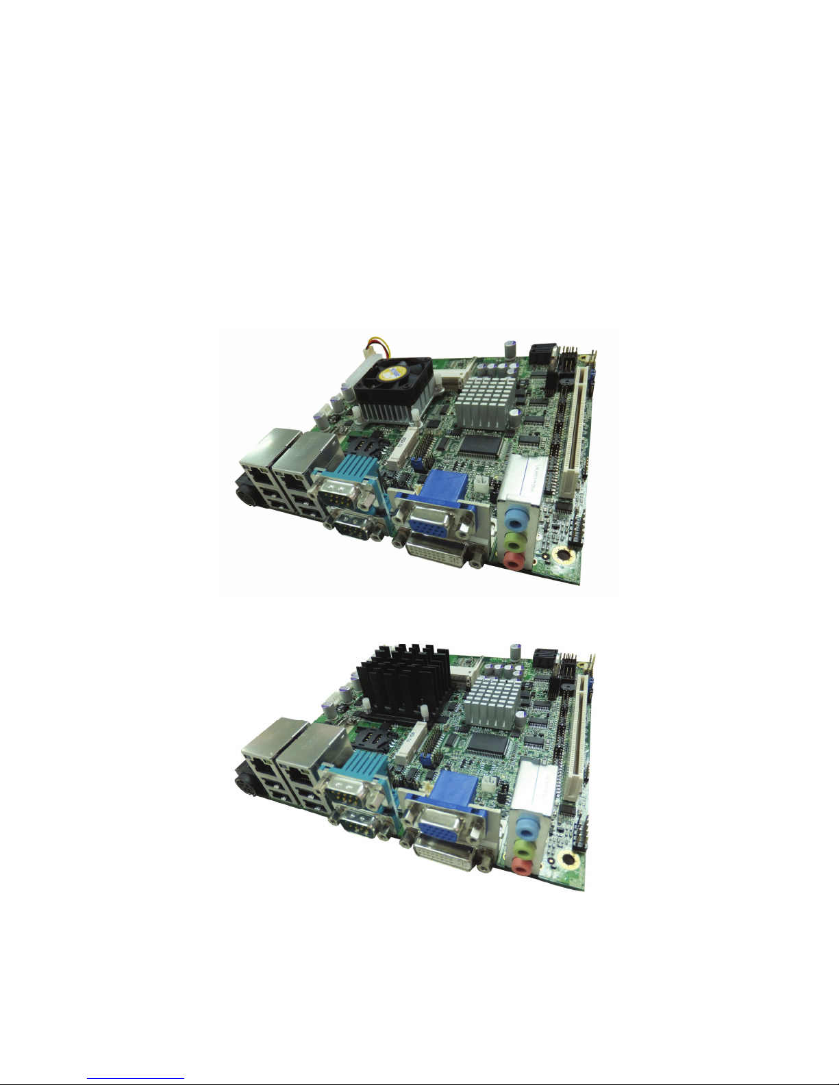
R-102-D5/N6/N8 Series
Mini-ITX Motherboard Support Socket G2 for
Intel® ATOM D2550/N2600/N2800 CPU, VGA/LVDS/DVI,
Dual GbE, PCI, SATA 3Gb/s and Audio
.
R-102-D5
R-102-N6/N8
Page 2
R-102 Series User’s Manual
2
R-102-D5/N6/N8
USER’S MANUAL
Note :
1. R-102-XX series : 2x LAN, 6x COM port.
2. R-102L-XX series : 1x LAN, 2x COM port.
Rev. A1.0 - Nov 15, 2012
Model No. Description
R-102-D5 Intel ATOM D2550 1.86 GHz 2x 512K L2, 10W TDP, dual-core CPU
R-102-N6 Intel ATOM N2600 1.6 GHz 2x 512K L2, 3.5W TDP, dual-core CPU
R-102-N8 Intel ATOM N2800 1.86 GHz 2x 512K L2, 6.5W TDP, dual-core CPU
Page 3
Revision
3
Revision
Date Version Changes
Nov 15, 2012 A1.0 Initial release
Page 4

R-102 Series User’s Manual
4
Notice
Copyright
The copyright of this user’s guide belongs to any authorized
company and is protected by copyright law. This means partial or
full duplication of this document (electronically, mechanically or
otherwise) is prohibited without the permission of the authorized
company.
The contents may be modified without notice for the improvement
of design, function, and reliability.
We do not guarantee the prevention of data loss. Please be
cautious not to lose important data and keep back-ups at all times.
Even though we did our best in drawing up this user’s guide, there
may be omissions and errors we failed to notice. Manufacturers
and suppliers cannot be held liable for problems stemming from
those errors and omissions.
Registered Trademark
Microsoft Windows 7 is a registered trademark of Microsoft.
Intel ATOM are registered trademarks of Intel.
Company names and product names mentioned in this document
are used to help your understanding and are registered
trademarks.
Page 5

Notice
5
Introduction
Thanks for choosing the next generation high performance motherboard
“R-102-D5/N6/N8 series”. The uses the high performance Intel® NM10 chipset
that will deliver superior performance to your computer.
About This User’s Guide
This User’s Guide is for assisting system manufactures and end user in setting
up and installing the motherboard. Information in this guide has been carefully
checked for reliability, however, there may still be inaccuracies and information
in this document is subject to change without notice.
DISCLAIMER
The information in this manual has been carefully checked and is believed to
be accurate. We assume no responsibility for any inaccuracies that may still be
contained in this manual. We reserve the right to make changes to this material
at any time without notice.
REMARK
Intel® ATOM CPU is registered trademark of Intel Corp.
All other trademarks mentioned in this manual are registered property of the
respective owners.
Page 6

R-102 Series User’s Manual
6
Page 7

Table of Content
7
Table of Content
Notice ............................................................................................ 4
Copyright ...................................................................................................4
Registered Trademark ..............................................................................4
Introduction ...............................................................................................5
About This User’s Guide ..........................................................................5
DISCLAIMER..............................................................................................5
REMARK ....................................................................................................5
Table of Content ........................................................................... 7
Chapter 1 : Unpacking ...............................................................10
1.1 Anti-static Precautions ..................................................................... 10
1.2 Unpacking Precautions ....................................................................10
1.3 Packing List ....................................................................................... 11
1.3.1 Optional Items......................................................................................................11
Chapter 2 : Introduction............................................................. 12
2.1 Introduction ....................................................................................... 12
2.2 Connectors ........................................................................................ 13
Front side : ................................................................................................................... 13
2.3 Dimensions........................................................................................14
2.3.1 Board Dimensions............................................................................................... 14
2.3.2 External Interface Panel Dimensions.................................................................. 15
2.4 Block Diagram Block Diagram .........................................................16
2.5 Technical Specifications...................................................................17
Chapter 3 : Connectors.............................................................. 20
3.1 Peripheral Interface Connectors......................................................20
3.1.1 R-102 Series Layout ........................................................................................... 20
3.2 Internal Peripheral Connectors/Jumpers ........................................ 21
3.2.1 Audio Connector : CN_AUDIO1(Pitch 2.54mm) ................................................. 21
3.2.2 SPDIF Connector : CN_SPDIF1(Pitch 2.0mm) .................................................. 22
3.2.3 Boot Up Mode Jumper : CN_AT1(Pitch 2.0mm)................................................. 22
3.2.4 Front Panel Connector : CN_PANEL2 (Pitch 2.54mm) ...................................... 23
3.2.5 Clear CMOS Jumper : CN_JRTC1(Pitch 2.54mm)............................................. 24
3.2.6 COM2 RS232/422/485 Jumper : (Pitch 2.0mm) CN_JCOM2_SEL1 /
CN_JCOM2_SEL2 ....................................................................................................... 25
3.2.7 COM1 / COM2 Voltage Setting Jumper : (Pitch 2.0mm) CN_JCOM1 /
Page 8

R-102 Series User’s Manual
8
CN_JCOM2.................................................................................................................. 26
3.2.8 COM3~6 Connector : CN_COM3~6(Pitch 2.0mm)............................................. 27
3.2.9 COM3~6 Voltage Setting Jumper : CN_JCOM3~6 (Pitch 2.0mm) ..................... 28
3.2.10 SPI Flash Connector : CN_SPI1 (Pitch 1.27mm) ............................................. 28
3.2.11 LVDS Voltage Jumper : CN_ JLVDS1 (Pitch 2.54mm) ..................................... 29
3.2.12 PS2 KB/Mouse Connector : CN_PS1 (Pitch 2.0mm) ....................................... 29
3.2.13 LVDS Connector : CN_LVDS1(Pitch 1.25mm) ................................................. 30
3.2.14 LVDS Panel Type Select : CN_JLVDS_SEL1(Pitch 2.0mm) ............................ 31
3.2.15 Panel On/Off : CN1(Pitch 2.0mm)..................................................................... 32
3.2.16 Digital I/O Connector : CN_DIO1(Pitch 2.0mm) ............................................... 32
3.2.17 Inverter Power Connector : CN_INV1(Pitch 2.0mm) / CN_INV2(Pitch 1.25mm)
..................................................................................................................................... 33
3.2.18 Parallel Port : CN_LPT1(Pitch 2.0mm) ............................................................. 34
3.2.19 USB Connector : CN_USB1(Pitch 2.0mm) / CN_USB2 / CN_USB3(Pitch
2.54mm) ....................................................................................................................... 35
3.2.20 SMBUS Connector : CN_SMBUS1(Pitch 2.0mm)............................................ 36
3.2.21 CPU / SYSTEM FAN Power Connector : CPUFAN1 / SYSFAN1..................... 36
3.2.22 SATA Connector : SATA1~2 .............................................................................. 37
3.2.23 ATX / DC IN Power Connector : ATX1 / DC_IN1 .............................................. 38
3.3 External Peripheral Interface Connector Panel .............................. 39
3.3.1 Ethernet and USB 2.0 Connector ....................................................................... 39
3.3.2 Serial Port Connector : COM1 / COM2............................................................... 41
3.3.3 Display Connector : CRT / DVI ........................................................................... 42
3.3.4 Audio Connector : AUDIO_JACK1...................................................................... 43
Chapter 4 : Installation............................................................... 44
4.1 Before Installation.............................................................................44
4.2 Install the SO-DIMM DDR3 RAM....................................................... 45
4.3 Install the SIM card............................................................................46
4.4 Install the Mini PCI-E card ................................................................48
Chapter 5 : BIOS Setup .............................................................. 49
5.1 APM : .................................................................................................. 49
5.2 Programming Watch Dog Timer : ....................................................49
5.3 Power Loss :......................................................................................50
5.4 Flash BIOS :.......................................................................................51
5.4.1 Flash Tool ............................................................................................................ 51
5.4.2 Flash BIOS Procedure ........................................................................................ 51
Page 9

Table of Content
9
Page 10

R-102 Series User’s Manual
10
Chapter 1 : Unpacking
1.1 Anti-static Precautions
Make sure to adhere to the following guidelines:
Wear an anti-static wristband: Wearing an anti-static wristband can prevent
electrostatic discharge.
Self-grounding: Touch a grounded conductor every few minutes to
discharge any excess static buildup.
Use an anti-static pad: When configuring any circuit board, place it on an
anti-static mat.
Only handle the edges of the PCB: Don't touch the surface of the
motherboard. Hold the motherboard by the edges when handling.
1.2 Unpacking Precautions
When the motherboard is unpacked, please do the following:
Follow the antistatic guidelines above.
Make sure the packing box is facing upwards when opening.
Make sure all the packing list items are present.
WARNING!
Static electricity can destroy certain electronics. Make sure to follow the
ESD precautions to prevent damage to the product, and injury to the
Page 11
Chapter 1 : Unpacking
11
1.3 Packing List
The R-102 series is shipped with the following components:
Item and Part Number Quantity
R-102 series Motherboard 1
SATA cable (CAB-N07330) 2
Dual RS-232 cable with bracket (NBS-COMBK1) 1
LPT printer cable with bracket (NBS-LPTBK0) 1
I/O Shielding (BKT-IR2717) 1
Utility CD 1
User Manual 1
1.3.1 Optional Items
The following are optional components which may be separately purchased:
Item and Part Number Quantity
ATX 20pin DC power cable (CAB-M20AD0)
This cable is for use power adapter.
If you want use over 2x 3.5” HDD, please make sure the
watts of power adapter is enough to support.
1
Dual USB cable with bracket (CAB-M09U20) 1
KB/MS Y cable (CAB-N08B20) 1
If any of the components listed in the checklist below are
missing, do not proceed with the installation. Contact the
reseller or vendor.
Page 12
R-102 Series User’s Manual
12
Chapter 2 : Introduction
2.1 Introduction
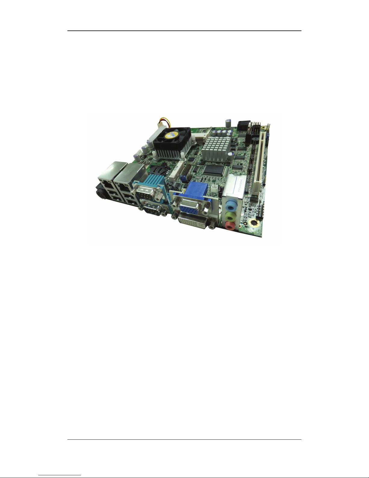
The R-102 series Mini-ITX motherboard is a Intel® ATOM processor platform.
Up to two 4.0 GB 800/1066 MHz DDR3 SDRAM SO-DIMM are supported by
the Intel® processor. NM10 chipset supports a PCI slot.
The integrated Intel® NM10 Express Chipset supports two GbE LAN: all
through the Intel® 82574L Ethernet controller, Wake-on-LAN, PXE ready
The Intel® NM10 also supports two SATA 3Gb/s drives.
The R-102 series supports multiple display devices, including 18-bit or 24-bit
dual-channel LVDS, analog CRT, and DVI. 6x USB 2.0 channels,
and one expansion PCIe mini socket. High Definition Audio (HDA) support
ensures HDA devices can be easily implemented on the R-102 series.
Page 13
Chapter 2 : Introduction
13
2.2 Connectors
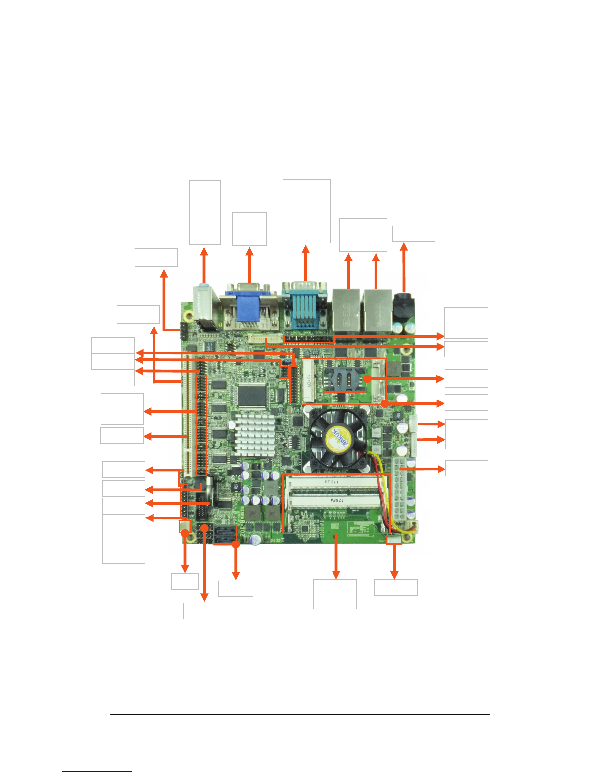
The connectors on the R-102 series are shown in the figure below.
Front side :
LAN and
USB 2.0
VGA
DVI
DB-9
Serial port :
COM1
COM2
Audio :
Line In
Line Out
Mic
Front Audio
SPDIF
SIM Socket
Mini PCIe
Digital I/O
Buzzer
Battery
DB-9 Serial port :
COM3~6
PCI slot
Power / Reset
Buttons,
Indicators
CMOS/AT/ATX
USB 1/2/3
SATA1/2
DDR3 So-DIMM
Socket
PS2 KB/MS
SMBUS
SYS FAN
ATX 20pin
LVDS Panel
Voltage supply
DC IN 4pin
LVD S
Parallel port
DB-9 Serial port :
COM1~2
Page 14
R-102 Series User’s Manual
14
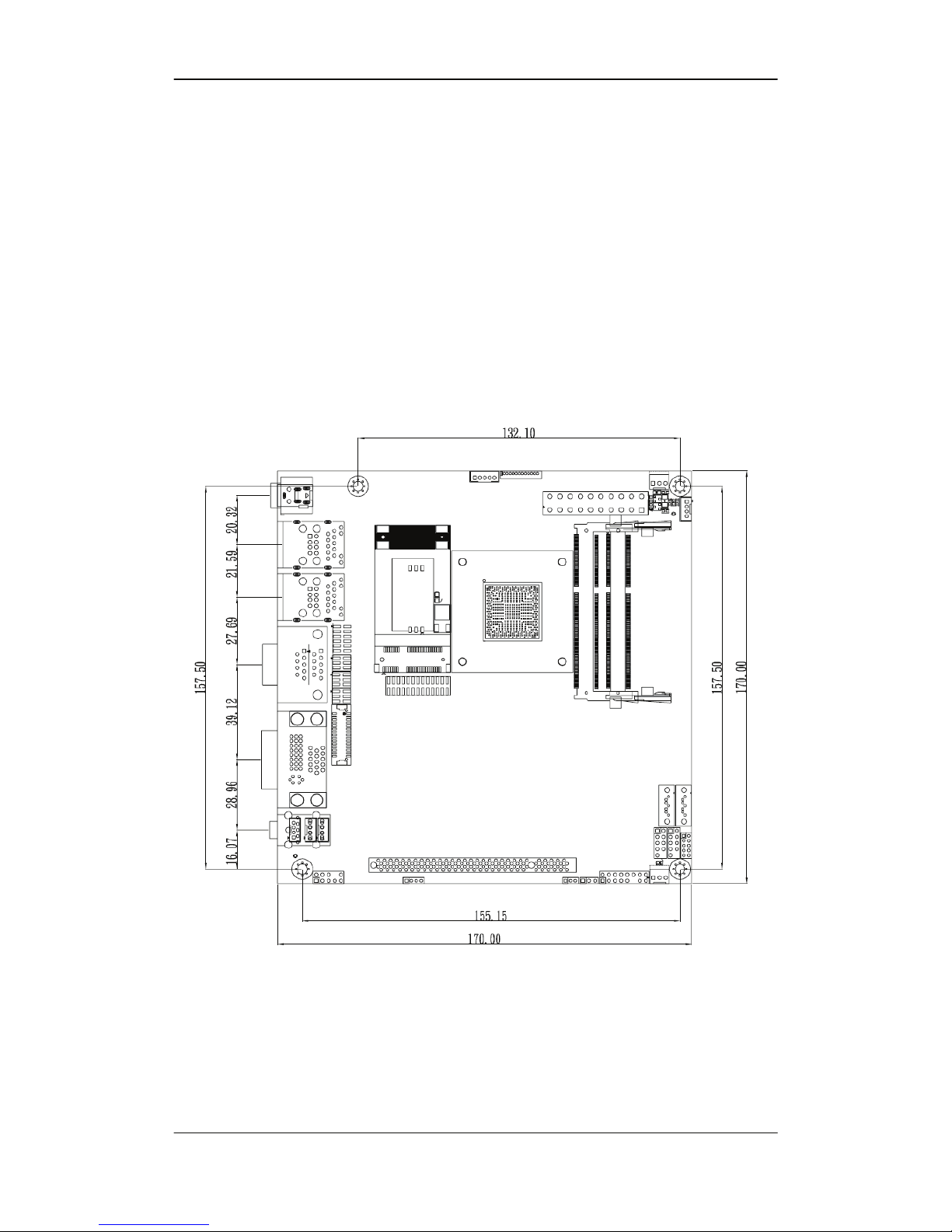
2.3 Dimensions
2.3.1 Board Dimensions
The dimensions of the board are listed below :
Length: 170 mm / Width: 170 mm
Page 15
Chapter 2 : Introduction
15
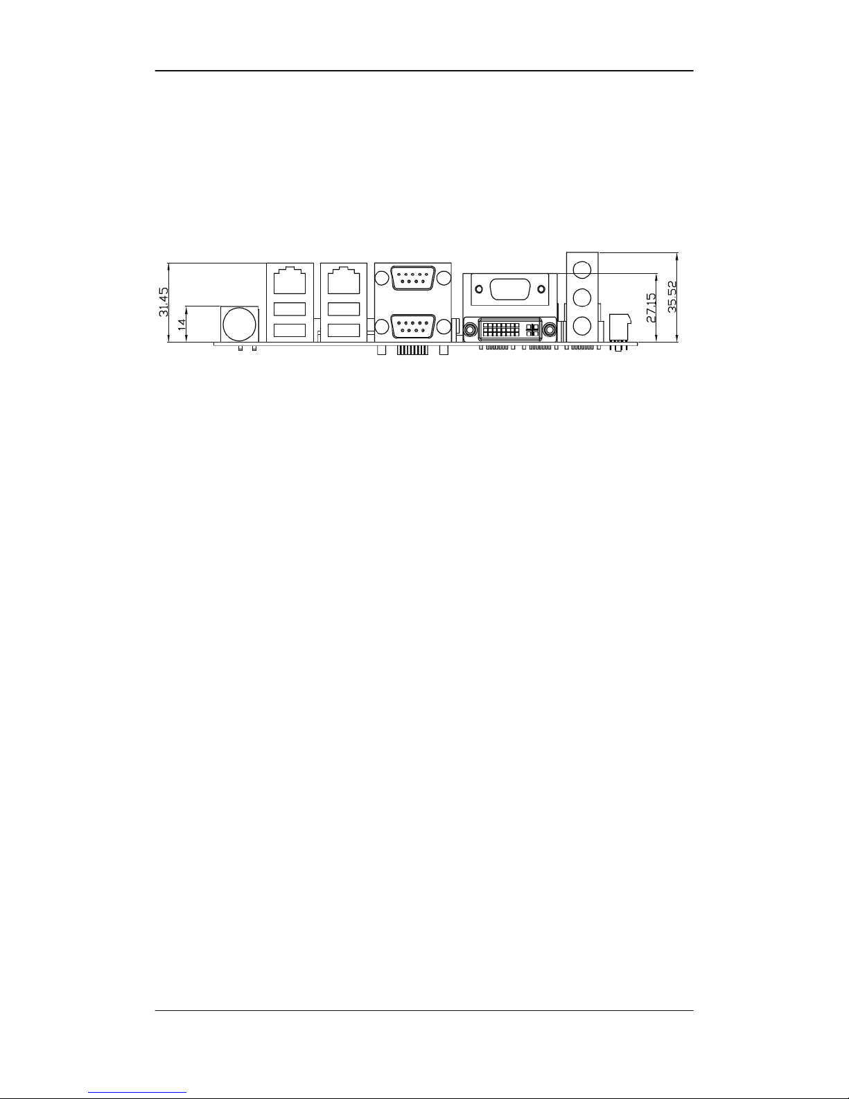
2.3.2 External Interface Panel Dimensions
External peripheral interface connector panel dimensions are shown below :.
Page 16
R-102 Series User’s Manual
16
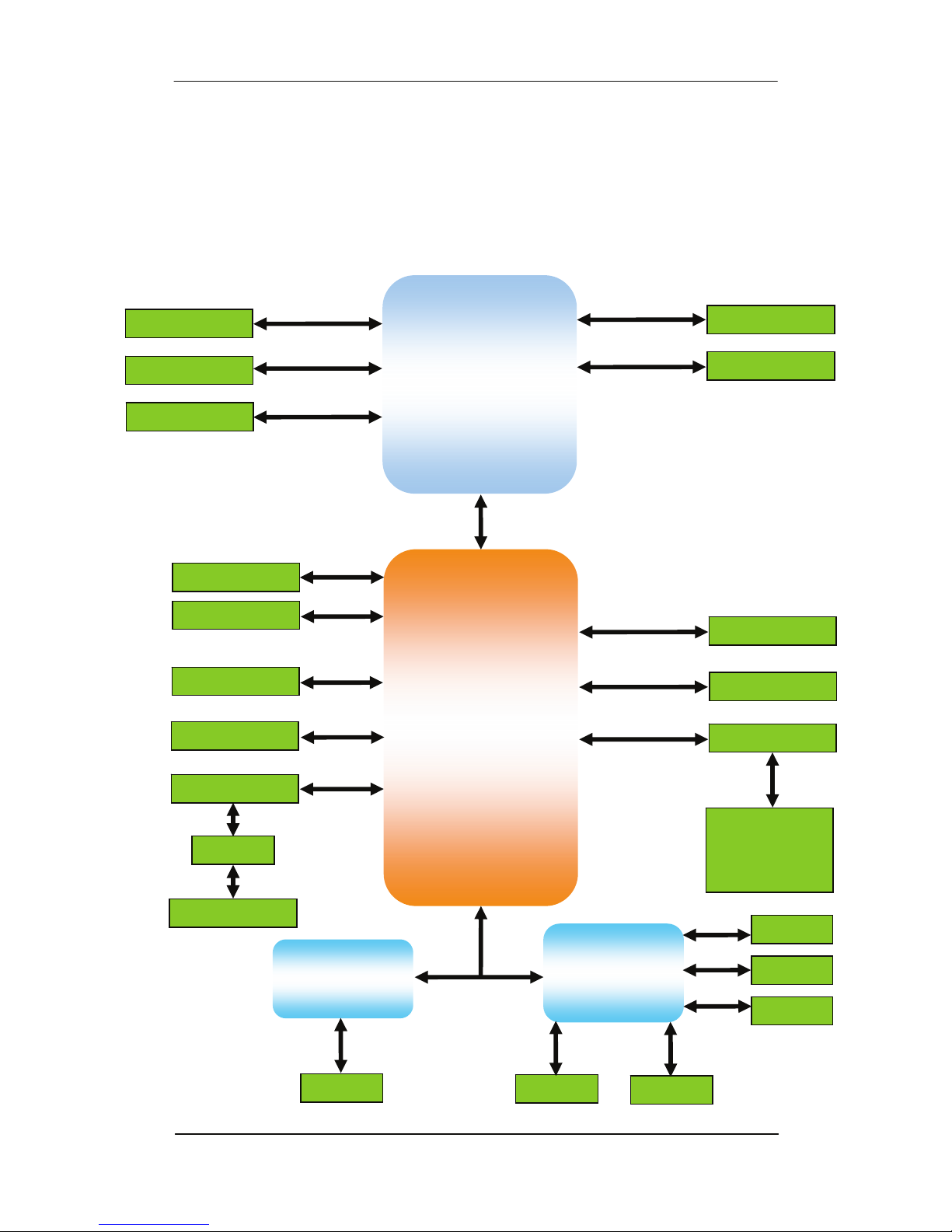
2.4 Block Diagram Block Diagram
The data flow between the two on-board chipsets and other components
installed on the motherboard and described in the following sections of this
chapter.
SO-DIMM1
(800/1066 MHz)
Intel® ATOM
D2550 / N2600 / N2800
Processor
Intel®
NM10
Interface 20-Gbit/s
SO-DIMM2
DDR3 SDRAM
LVDS (18/24bit)
VGA
DVI
2x SATA II
SPI ROM
Realtek ALC888
Audio Jacks
Audio Connector
SPDIF
2x Intel®82547L
Mini PCIe Slot
7x USB 2.0
BIOS debug port
Super I/O
W83627DHG
Fintek
F81216AD
COM1~2
2 x FAN
8-bit DIO
KB/MS
COM3~6
CRT
DP CH7511B
PCIe x1
USB
SMBUS
LPC
GPIO
LPC
PCIe x2
HD Audio
SPI
SATA
Channel A
Channel B
PCI Slot
32bit/33MHz PCI Bus
AU 6258
3x USB 2.0
LPT
Page 17

Chapter 2 : Introduction
17
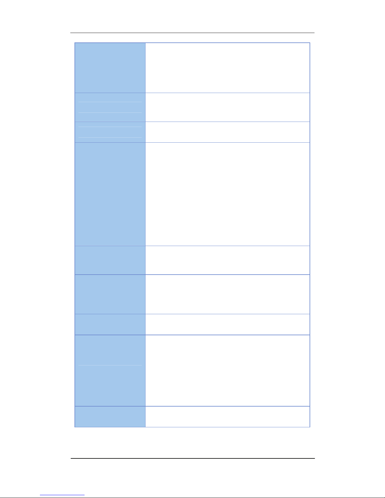
2.5 Technical Specifications
R-102 technical specifications are listed in table below.
Processor
Intel® AtomTM processor N2800, 1.86 GHz 2x 512K L2,
6.5W TDP, dual-core heatsink (fanless solution)
Intel® AtomTM processor N2600, 1.6 GHz 2x 512K L2,
3.5W TDP, dual-core heatsink (fanless solution)
Intel® AtomTM processor D2550, 1.86 GHz 2x 512K L2, 10W
TDP, dual-core heatsink (with cooling fan)
Chipset Intel® NM10 Express Chipset
Memory
2 x DDR3-800/1066 SO-DIMM up to 8 GB
technologies are supported for x8 and x16 devices,
unbuffered, non-ECC
at 800/1066 MHZ on N2800 and D2550(Max 8GB)
at 800 MHZ on N2600(Max 4GB)
(ATOM N2600 only support one memory module.)
(When you install only one memory module, install it on
SO-DIMM 2 slot)
Storage 2 x SATAII interface with 300MB/s transfer rate
Video
Intel® GMA 3650 graphics core for N2800 and D2550
Intel® GMA 3600 graphics core for N2600
Supports Hardware H.264/AVC, MPEG-2 video decoder,
VC-1, DirectX 9, 1080p decoder
Onboard 24-bit dual channel LVDS interface with
3.3V/5V/12V Support
VGA display resolution up to 1920x1200
Page 18
R-102 Series User’s Manual
18
LVDS supports 24-bit dual-channel by CH7511 DP to
LVDS converter, resolution support up to
1920x1200 for D2550, 1600x1200 for N2600/N2800
Audio
Realtek ALC888 HD 6-channel CODEC
Line out / line in / microphone ports
Super I/O W83627DHG
Interface ports
Rear side :
2x Serial, DB-9 connector :
1x RS232(COM1), 1x RS485/422/232(COM2)
VGA(CRT)
DVI
2x RJ45 LAN
4x USB 2.0
Line out / line in / microphone.
DC In
USB Port
External : 4x USB 2.0 ports.
Internal : 6x USB 2.0 (6x jumper pin) ports.
Expansion Slots
1x PCI slot
1x Mini PCI-E slot
1x SIM socket
Communications Intel 82574L Gigabit LAN, Wake-on-LAN, PXE ready
Internal I/O port
1x PS2 KB/Mouse (8-pin header)
1x SMBus (4-pin header)
1x SPDIF/out (4-pin header)
1x GPIO (Onboard Programmable 8-bit Digital I/O
interface(4 In+4 Out), 12-pin header) ;
4x RS232 (COM3/4/5/6, 10-pin header)
BIOS UEFI BIOS label
Page 19

Chapter 2 : Introduction
19
Watchdog Timer Software programmable supports 1~255 sec. system reset
Boot Up mode ATX / AT
Power Connector
Standard 20-pin ATX power supply and
Power adapter DC 9 ~ 24V input
Operation Humidity 10% ~ 95% relative humidity, non-condensing
Temperature
Operating: 0°C ~ +60°C (32°F ~ 140°F), Storage: -20°C ~
+80°C (-4°F ~ +176°F)
Dimensions Mini-ITX form factor, 170mm (L) x 170mm(W)
Weight GW/NW 900g/320g
Page 20
R-102 Series User’s Manual
20
Chapter 3 : Connectors
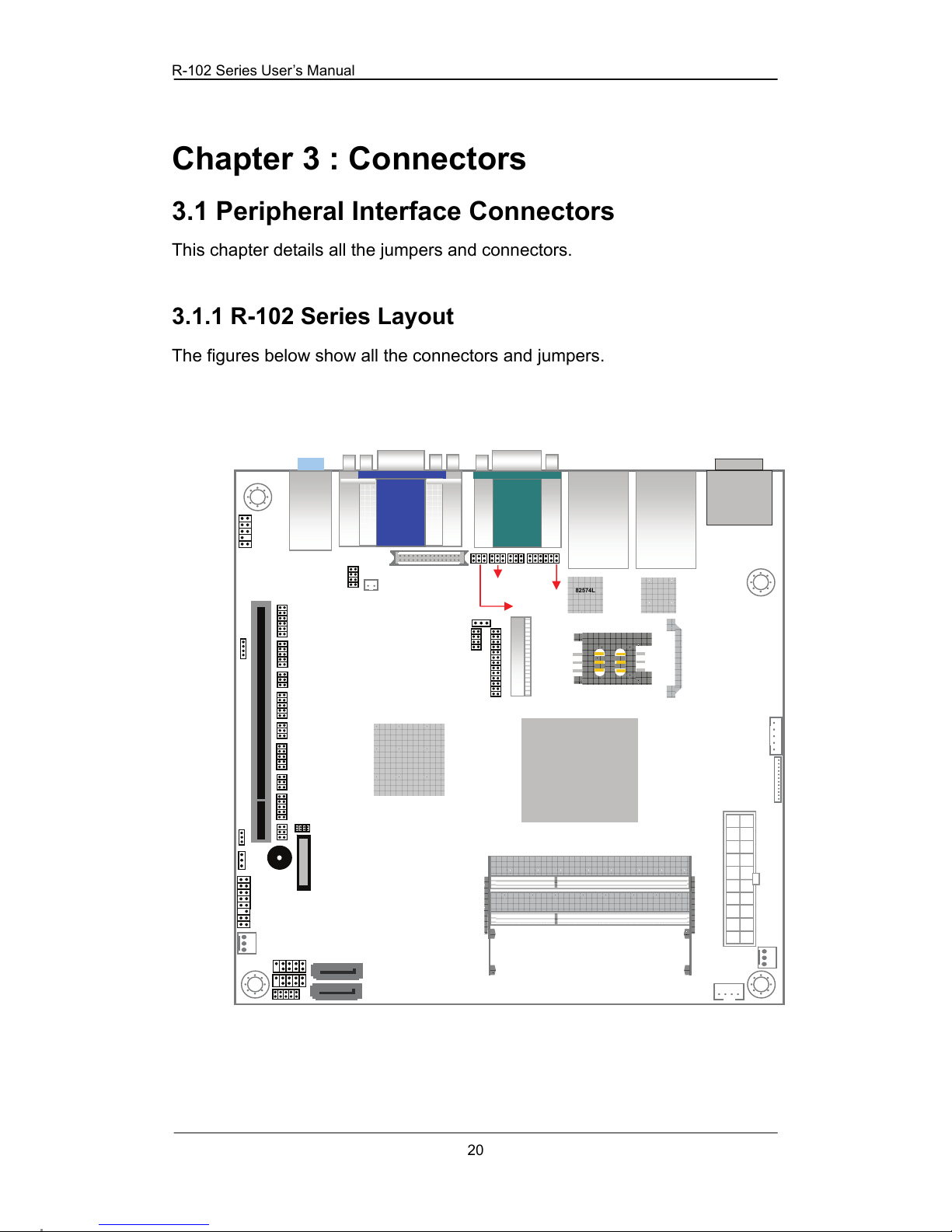
3.1 Peripheral Interface Connectors
This chapter details all the jumpers and connectors.
3.1.1 R-102 Series Layout
The figures below show all the connectors and jumpers.
82574L
82574L
NM10
SO-DIMM1
CPU FAN1
SO-DIMM2
A
TX1
CN SMBUS1
SYS FAN1
CN_INV1
CN_INV2
SATA2
SATA1
CN_USB2
CN_USB3
CN_USB1
CN
_
PAN EL2
CN_SPI1
CN_AT1
CN_JCOM5
CN_COM5
CN
_
SPDIF1
CN_AUDIO1
CN_JLVDS1
CN_JLVDS_SEL1
CN_LPT1
CN_DIO1
MINI_CARD1
CN_SIM1
CN_LVDS1
CN_JCOM2_SEL1
CN_JCOM1
CN_JCOM2
CN_JCOM2_SEL2
USB_RJ45_2 USB_RJ45_1
COM1(TOP)_COM2
DVI_CRT
A
UDIO_JACK1
CN_PS1
CN1
CN_JCOM3
CN_COM3
CN_JCOM4
CN_COM4
CN_JCOM6
CN_COM6
CN_JRTC1
ATO M
D2550 /
N2600 / N2800
Page 21
Chapter 3 : Connectors
21
3.2 Internal Peripheral Connectors/Jumpers
The section describes all of the connectors on the R-102 series.
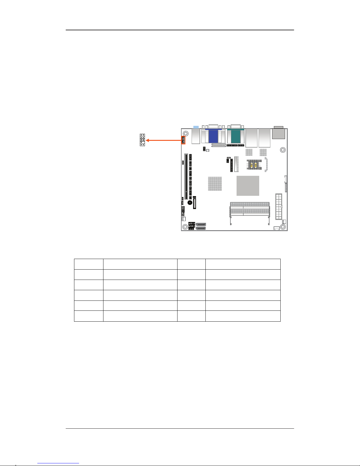
3.2.1 Audio Connector : CN_AUDIO1(Pitch 2.54mm)
PIN NO. DESCRIPTION PIN NO. DESCRIPTION
1 MIC2L 2 GND
3 MIC2R 4 ACZ_DET
5 LINE2R 6 MIC2_JD
7 FRONT_SENSE 8 NC
9 LINE2L 10 LINE2_JD
1
10
2
9
Page 22
R-102 Series User’s Manual
22
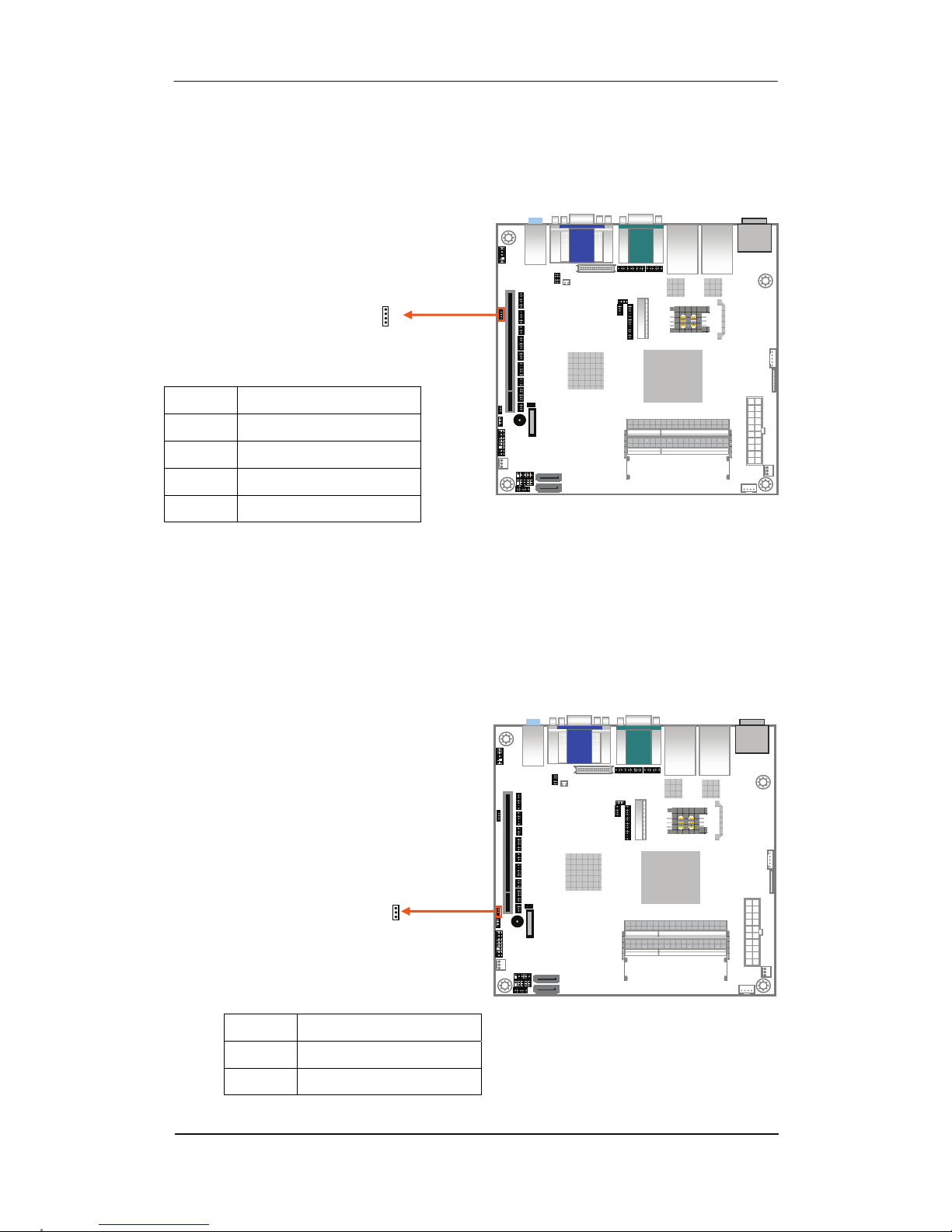
3.2.2 SPDIF Connector : CN_SPDIF1(Pitch 2.0mm)
3.2.3 Boot Up Mode Jumper : CN_AT1(Pitch 2.0mm)
PIN NO. DESCRIPTION
1 V5S
2 NC
3 SPDIFO
4 GND
PIN NO. DESCRIPTION
1-2 AT Mode
2-3 ATX Mode
1
4
1
3
Page 23
Chapter 3 : Connectors
23
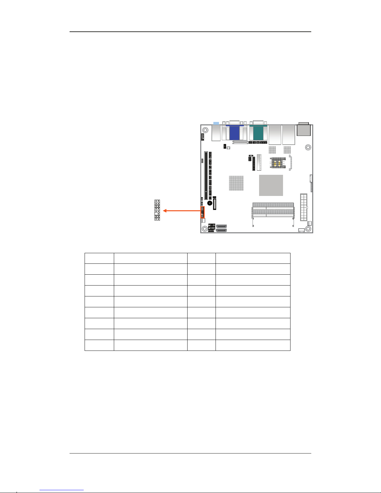
3.2.4 Front Panel Connector : CN_PANEL2
(Pitch 2.54mm)
PIN NO. DESCRIPTION PIN NO. DESCRIPTION
1 HDD LED+ 2 Power LED+
3 HDD LED- 4 NC
5 NC 6 GND
7 RST- 8 NC
9 GND 10 SPEAK+
11 NC 12 NC
13 PW_BN+ 14 NC
15 PW_BN- 16 SPEAK-
1 2
15 16
Page 24
R-102 Series User’s Manual
24
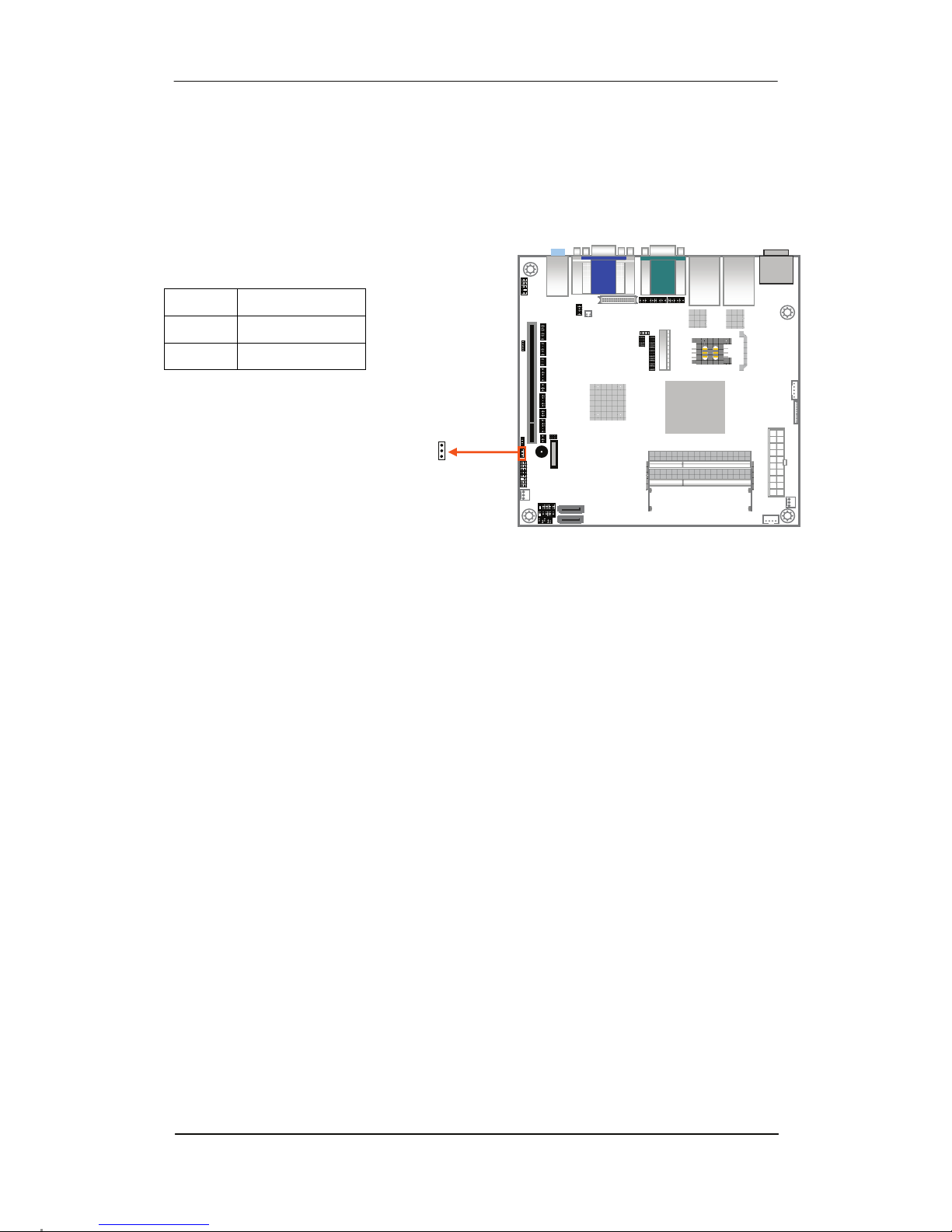
3.2.5 Clear CMOS Jumper : CN_JRTC1(Pitch 2.54mm)
PIN NO. DESCRIPTION
1-2 CLEAR CMOS
2-3 NORMAL
1
3
Page 25
Chapter 3 : Connectors
25
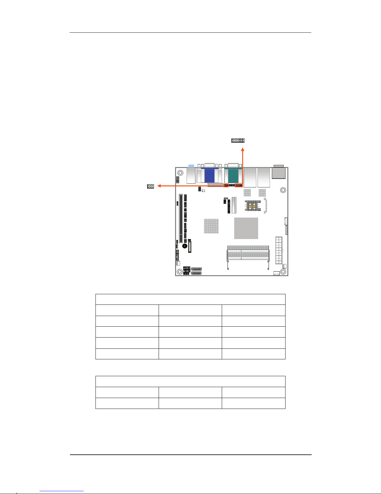
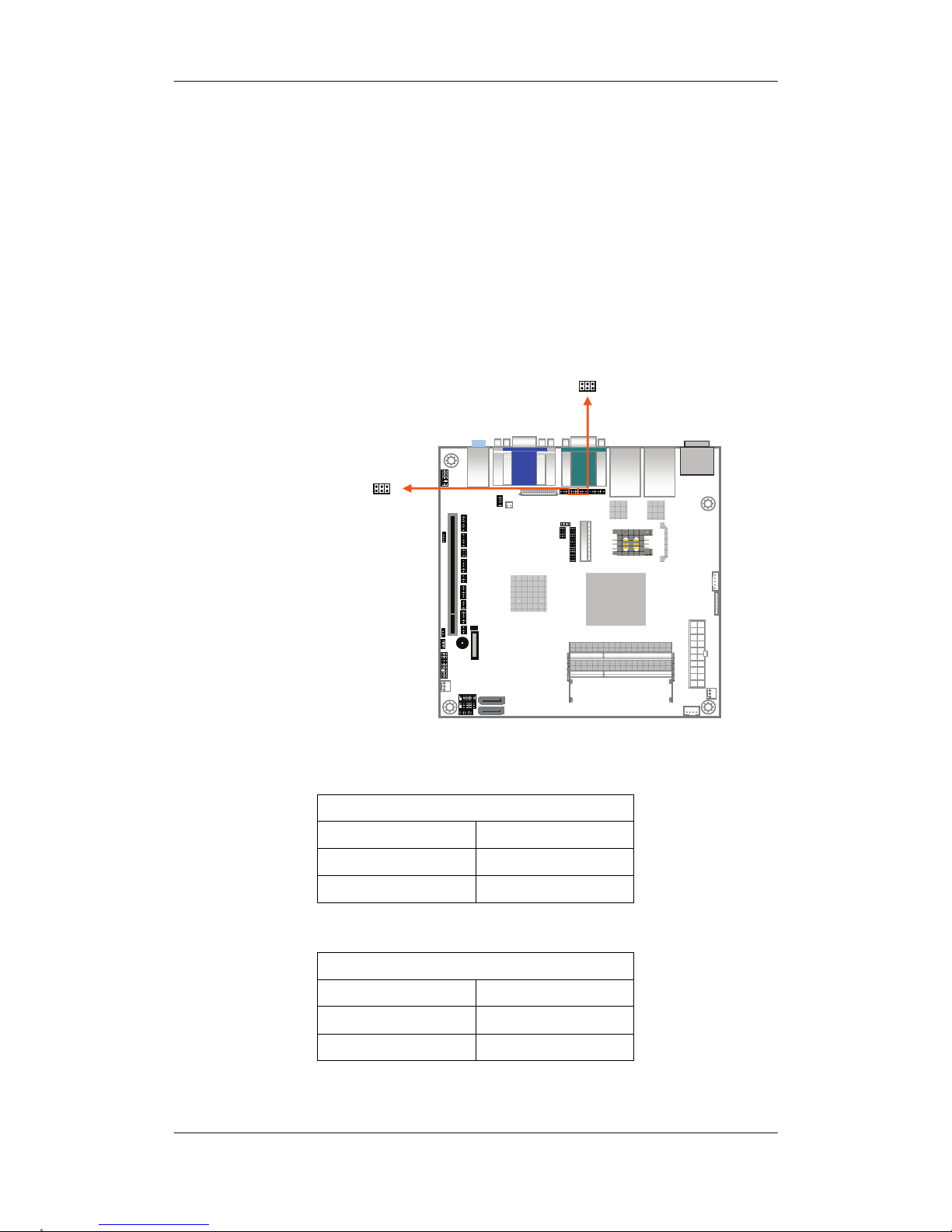
3.2.6 COM2 RS232/422/485 Jumper : (Pitch 2.0mm)
CN_JCOM2_SEL1 / CN_JCOM2_SEL2
CN_JCOM2_SEL1
RS232 RS485 RS422
1-3 3-5 3-5
2-4 4-6 4-6
7-9 9-11 9-11
8-10 10-12 10-12
CN_JCOM2_SEL2
RS232 RS485 RS422
1-2 3-4 5-6
1
2
11
12
1
2
5
6
CN_JCOM2_SEL1
CN_JCOM2_SEL2
Page 26
R-102 Series User’s Manual
26
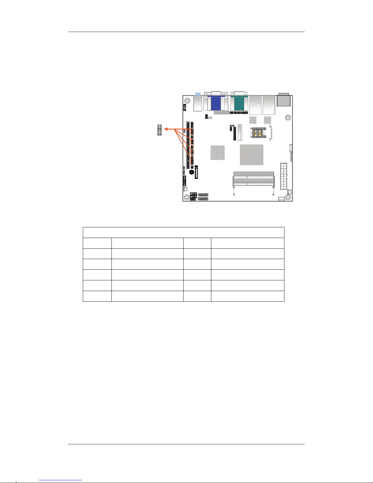
3.2.7 COM1 / COM2 Voltage Setting Jumper :
(Pitch 2.0mm)
CN_JCOM1 / CN_JCOM2
CN_JCOM1
1-2 +5V
3-4 RI
5-6 +12V
CN_JCOM2
1-2 +5V
3-4 RI
5-6 +12V
1
2
5
6
CN_JCOM1
CN_JCOM2
1
2
5
6
Page 27
Chapter 3 : Connectors
27
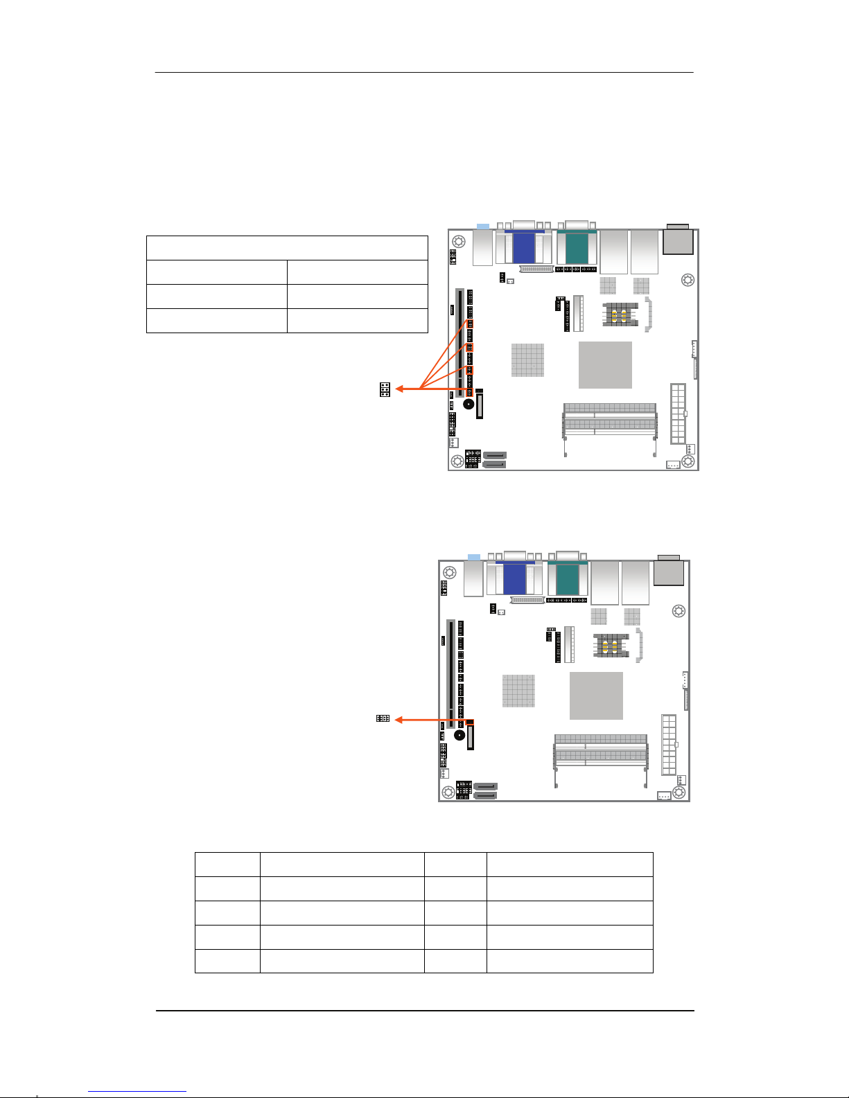
3.2.8 COM3~6 Connector : CN_COM3~6(Pitch 2.0mm)
CN_COM3~6
PIN NO. DESCRIPTION PIN NO. DESCRIPTION
1 HS_DCD(1~4)- 2 HS_RXD(1~4)
3 HS_TXD(1~4) 4 HS_DTR(1~4)-
5 GND 6 HS_DSR(1~4)-
7 HS_RTS(1~4)- 8 HS_CTS(1~4)-
9 HSRI(1~4) 10 NC
1 2
9
10
CN_COM3~6
Page 28
R-102 Series User’s Manual
28
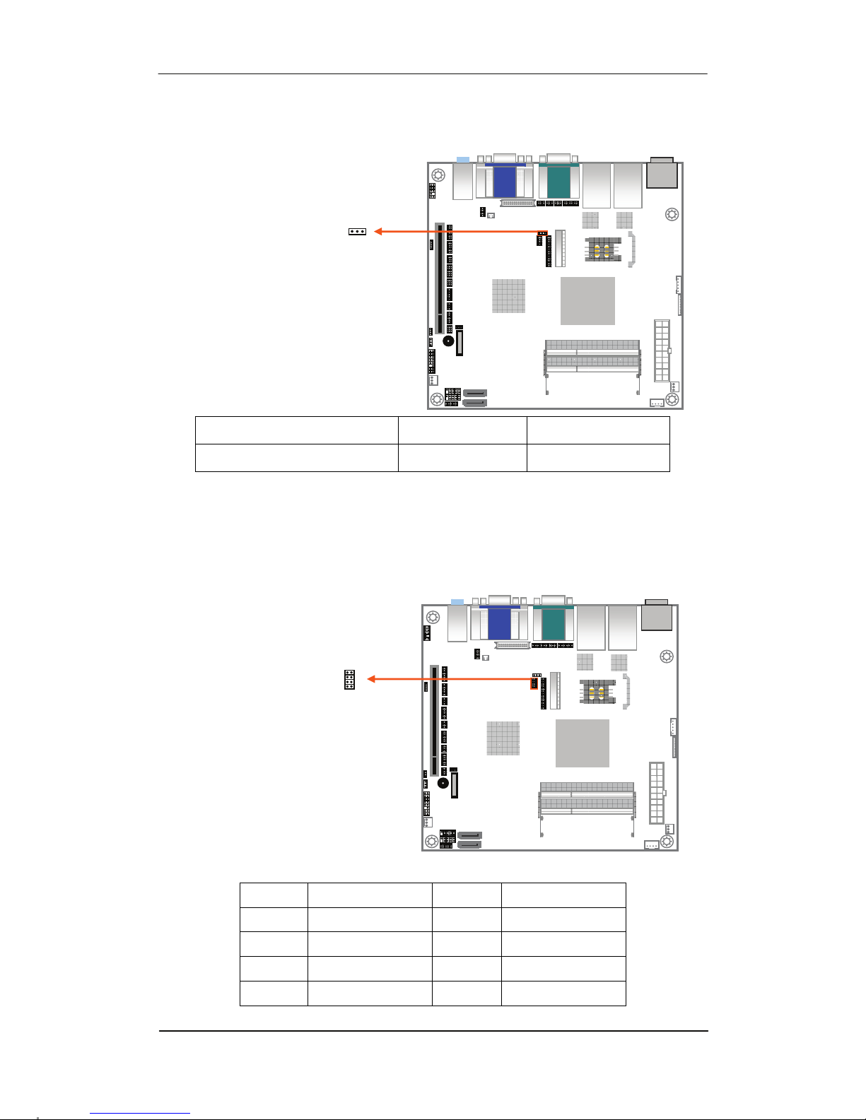
3.2.9 COM3~6 Voltage Setting Jumper : CN_JCOM3~6
(Pitch 2.0mm)
3.2.10 SPI Flash Connector : CN_SPI1 (Pitch 1.27mm)
CN_JCOM3~6
1-2 +5V
3-4 RI
5-6 +12V
PIN NO. DESCRIPTION PIN NO. DESCRIPTION
1 CS- 2 V3.3SPI
3 SO+ 4 -SPI HOLD0
5 NC 6 CLK+
7 GND 8 SI+
1
2
5
6
1
2
7
8
Page 29
Chapter 3 : Connectors
29
3.2.11 LVDS Voltage Jumper : CN_ JLVDS1
(Pitch 2.54mm)
PS : +12V for large size panel : This request please tell us to modify before order.
CN_JLVDS2 must open, RN15 use 0 ohm resistance to short.
3.2.12 PS2 KB/Mouse Connector : CN_PS1
(Pitch 2.0mm)
Panel >=17” +5V 1-2
Panel <=15” +3.3V 2-3
PIN NO. DESCRIPTION PIN NO. DESCRIPTION
1 BVCC 2 BVCC
3 MCL 4 KBCL
5 MDA 6 KBDA
7 GND 8 GND
1
3
1
2
8
7
Page 30
R-102 Series User’s Manual
30
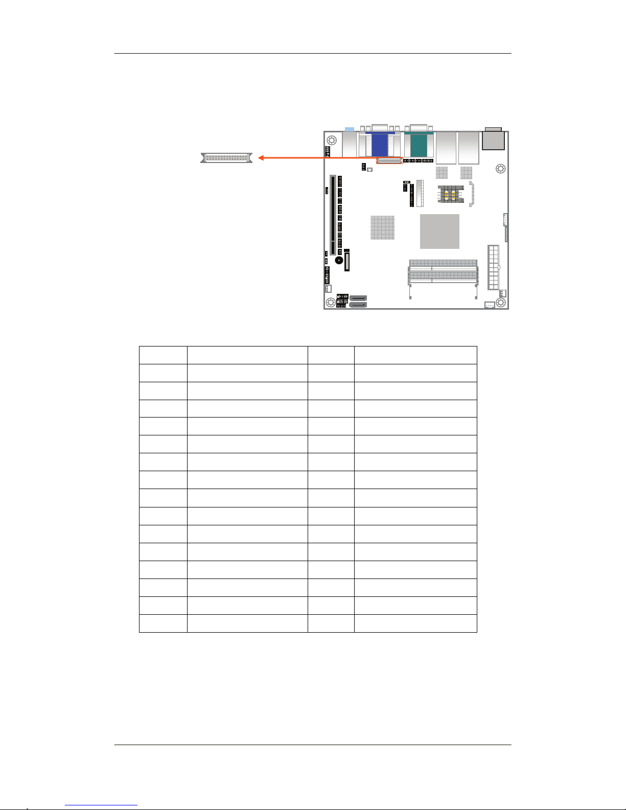
3.2.13 LVDS Connector : CN_LVDS1(Pitch 1.25mm)
PIN NO. DESCRIPTION PIN NO. DESCRIPTION
1 LCDVCC 2 LCDVCC
3 LCDVCC 4 NC
5 NC 6 NC
7 GND 8 L DC7P
9 L DC7N 10 L CLK2P
11 L CLK2N 12 L DC6P
13 L DC6N 14 GND
15 L DC5P 16 L DC5N
17 GND 18 L DC4P
19 L DC4N 20 L DC3P
21 L DC3N 22 L CLK1P
23 L CLK1N 24 GND
25 L DC2P 26 L DC2N
27 L DC1P 28 L DC1N
29 L DC0P 30 L DC0N
30
2
29
1
Page 31
Chapter 3 : Connectors
31
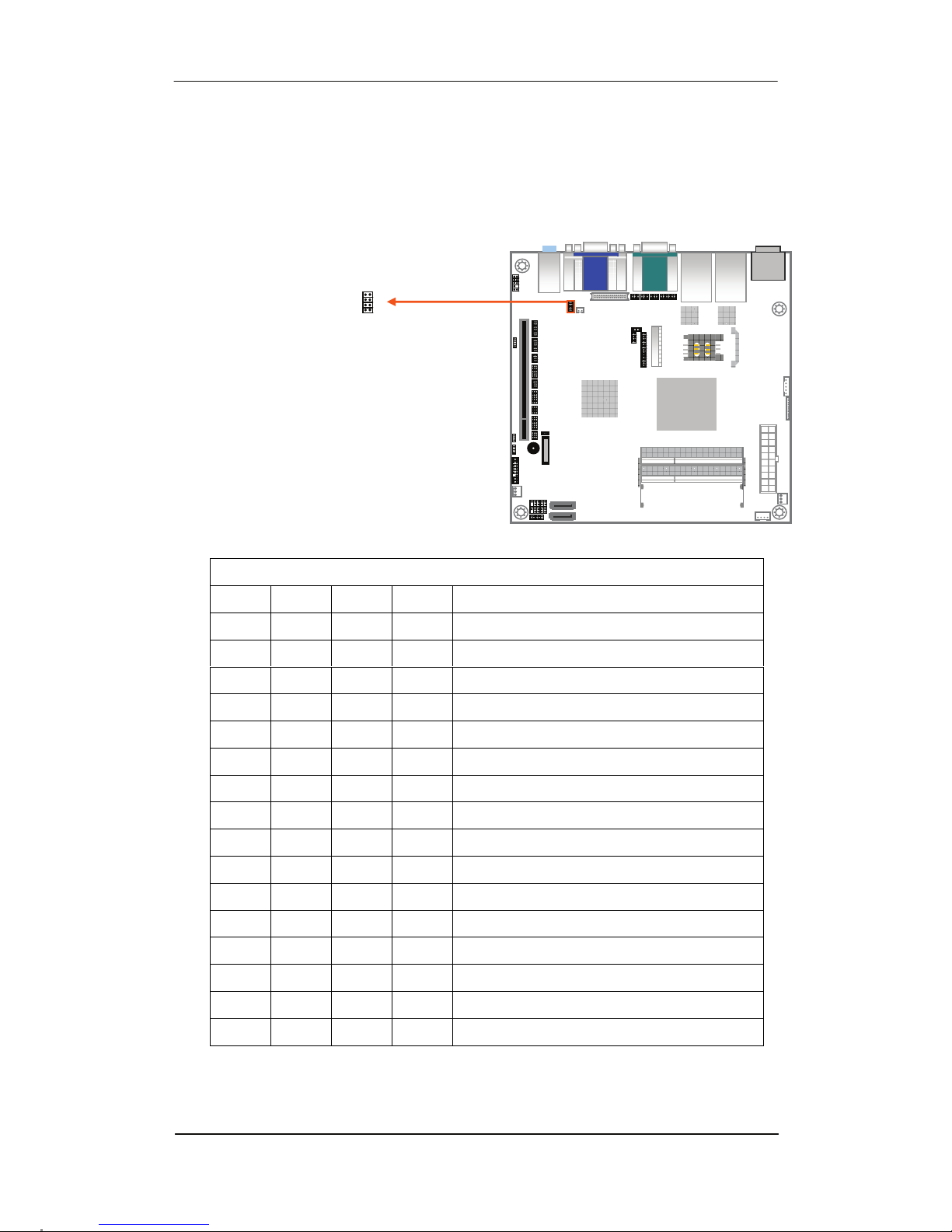
3.2.14 LVDS Panel Type Select :
CN_JLVDS_SEL1(Pitch 2.0mm)
Open = 1, Short = 0
7-8 5-6 3-4 1-2 Panel Type
0 0 0 0 800x600 18bit
0 0 0 1 1024x768 18bit
0 0 1 0 1024x768 24bit
0 0 1 1 1280x768 18bit
0 1 0 0 1280x800 18bit
0 1 0 1 1280x960 18bit
0 1 1 0 1280x1024 24bit
0 1 1 1 1366x768 18bit
1 0 0 0 1366x768 24bit
1 0 0 1 1440x900 24bit
1 0 1 0 1440x1050 24bit
1 0 1 1 1600x900 24bit
1 1 0 0 1680x1050 24bit
1 1 0 1 1600x1200 24bit
1 1 1 0 1920x1080 24bit
1 1 1 1 1920x1200 24bit
1
2
8
7
Page 32
R-102 Series User’s Manual
32
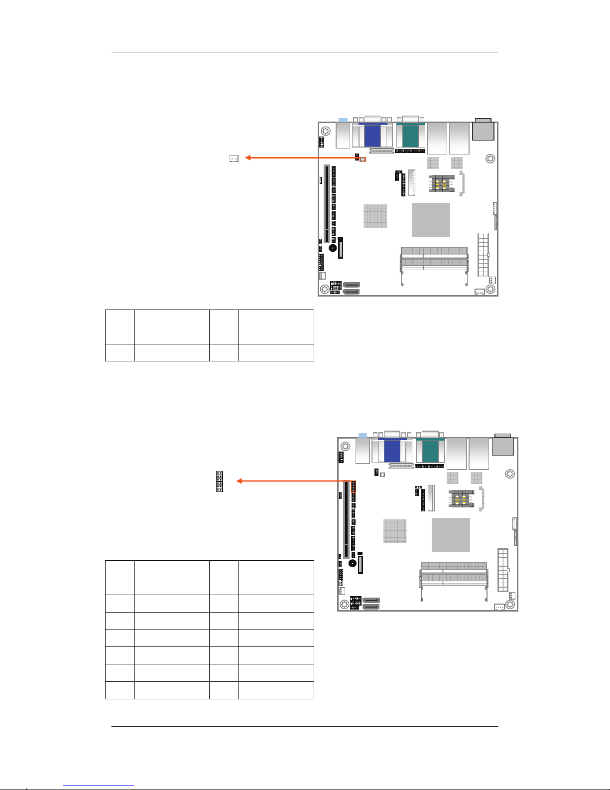
3.2.15 Panel On/Off : CN1(Pitch 2.0mm)
3.2.16 Digital I/O Connector : CN_DIO1(Pitch 2.0mm)
PIN
NO.
DESCRIPTION PIN
NO.
DESCRIPTION
1 L PWRON 2 GND
PIN
NO.
DESCRIPTION PIN
NO.
DESCRIPTION
1 GND 2 GND
3 GP10_IN0 4 GP14_OUT4
5 GP11_IN1 6 GP15_OUT5
7 GP12_IN2 8 GP16_OUT6
9 GP13_IN3 10 GP17_OUT7
11 V5S 12 V12S
1
2
11 12
1
2
Page 33
Chapter 3 : Connectors
33
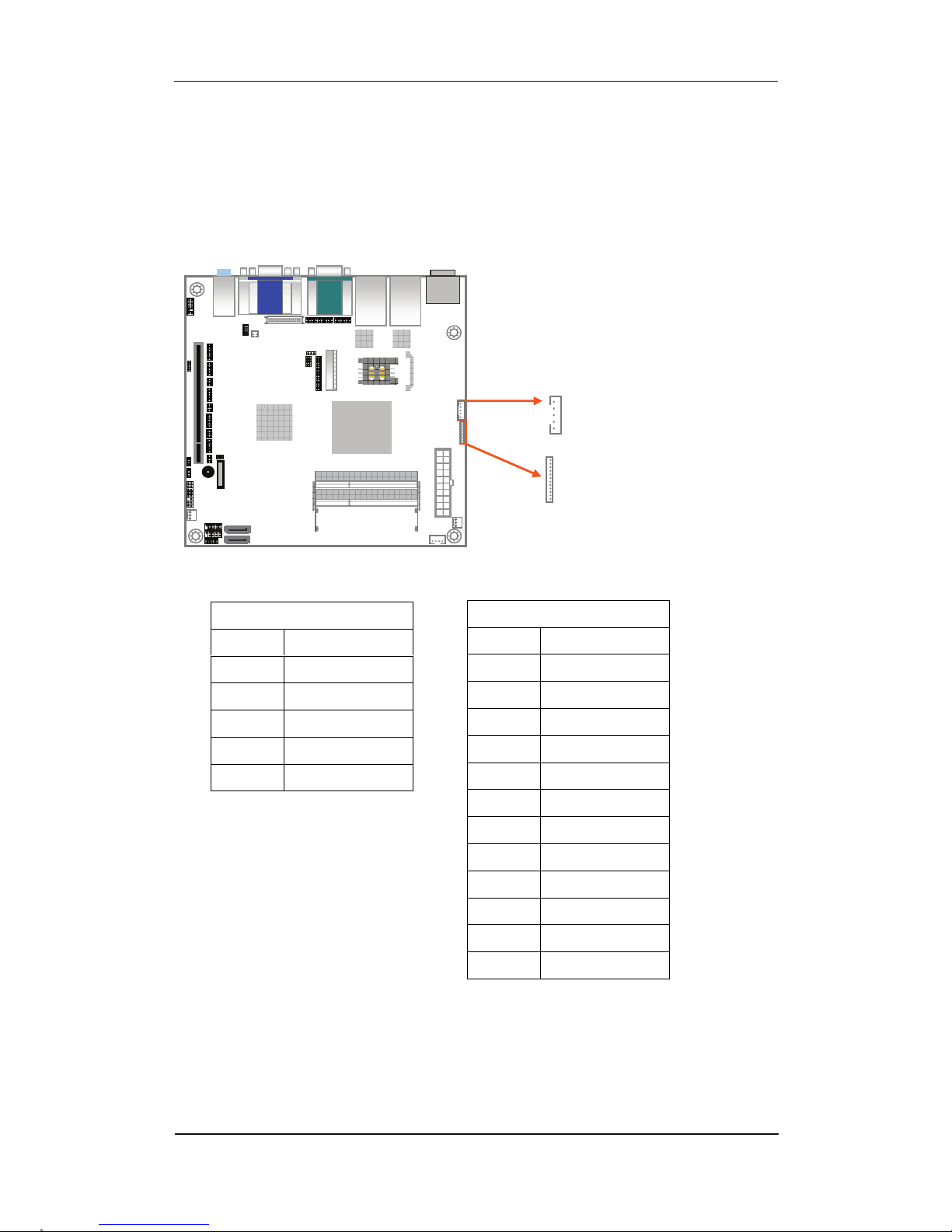
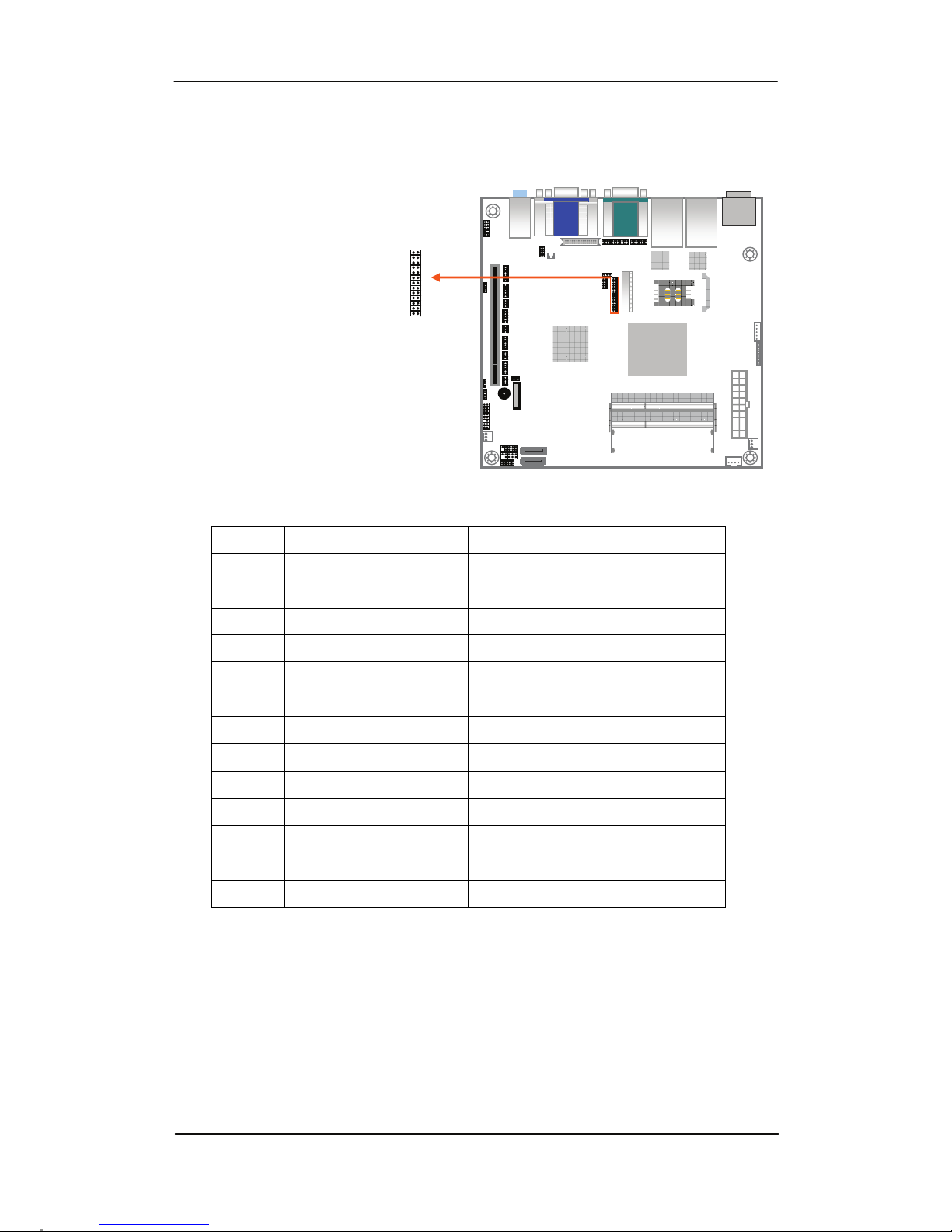
3.2.17 Inverter Power Connector :
CN_INV1(Pitch 2.0mm) / CN_INV2(Pitch 1.25mm)
CN_INV1
PIN NO. DESCRIPTION
1 V12S
2 BRIGHT
3 GND
4 GND
5 V5S (INV_ON)
CN_INV2
PIN NO. DESCRIPTION
1 GND
2 BRIGHT
3 GND
4 INV_ON
5 GND
6 GND
7 NC
8 GND
9 GND
10 V12S
11 V12S
12 V12S
1
12
5
1
CN_INV2
CN_INV1
Page 34
R-102 Series User’s Manual
34
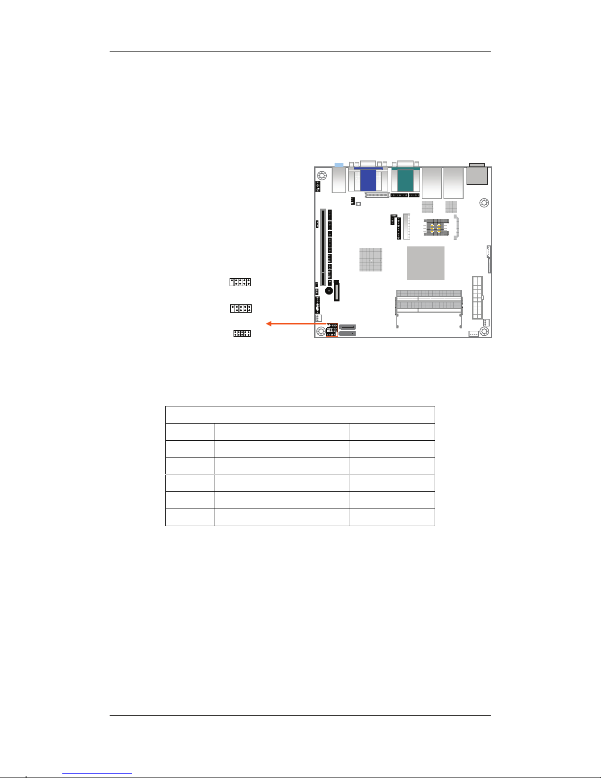
3.2.18 Parallel Port : CN_LPT1(Pitch 2.0mm)
PIN NO. DESCRIPTION PIN NO. DESCRIPTION
1 -PSTB 2 AFD-
3 PRD0 4 ERR-
5 PRD1 6 INIT-
7 PRD2 8 SLIN-
9 PRD3 10 LPTGND
11 PRD4 12 LPTGND
13 PRD5 14 LPTGND
15 PRD6 16 LPTGND
17 PRD7 18 LPTGND
19 ACK- 20 LPTGND
21 BUSY 22 LPTGND
23 PE 24 LPTGND
25 SLCT 26 LPTGND
1
2
25
26
Page 35
Chapter 3 : Connectors
35
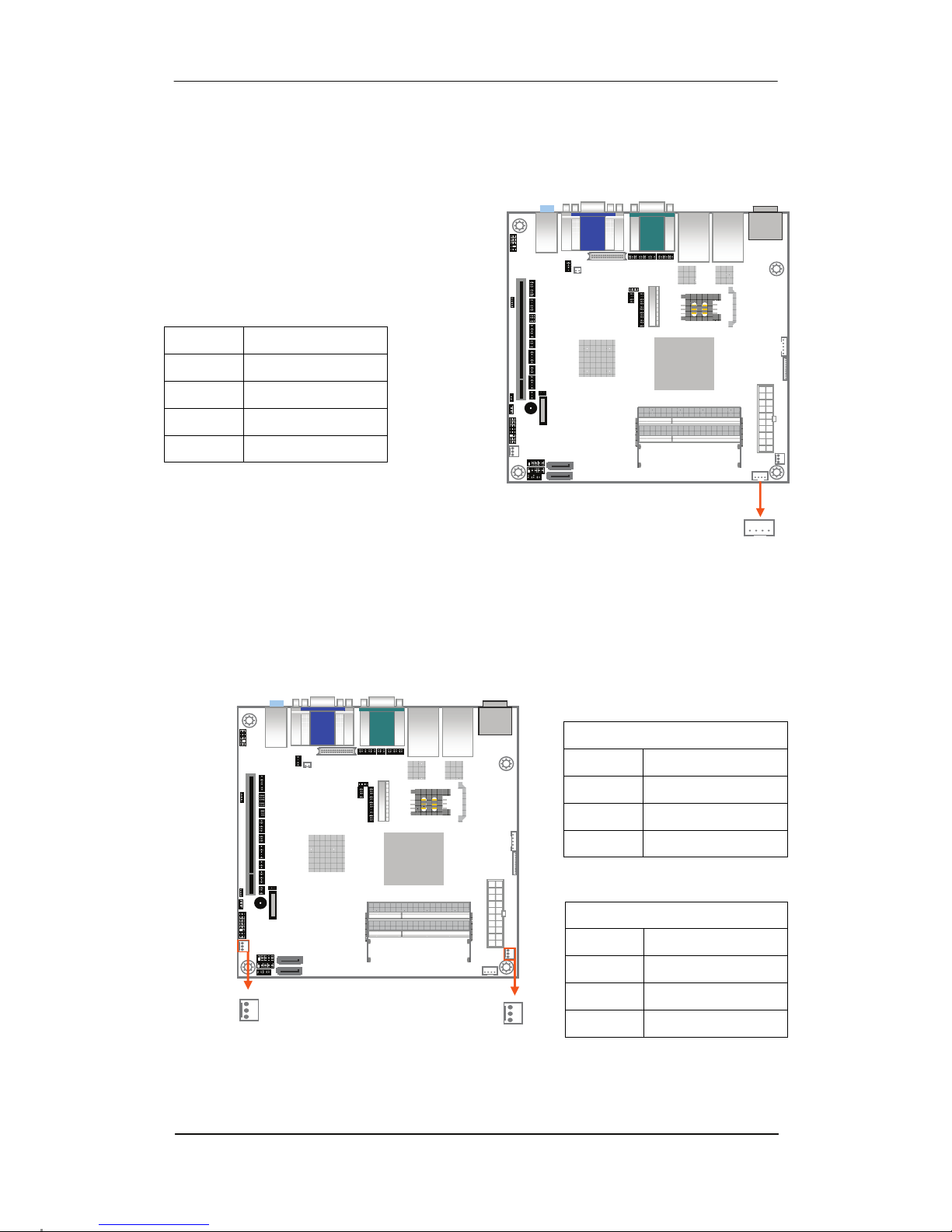
3.2.19 USB Connector : CN_USB1(Pitch 2.0mm) /
CN_USB2 / CN_USB3(Pitch 2.54mm)
CN_USB1 / CN_USB2 / CN_USB3
PIN NO. DESCRIPTION PIN NO. DESCRIPTION
1 VCC (5V SB) 2 VCC (5V SB)
3 DATA0- 4 DATA1-
5 DATA0+ 6 DATA1+
7 GND 8 GND
9 GND 10 GND
9
1
2
8
2
1
9
10
CN_USB2
CN_USB1
CN_USB3
9
1
2
8
Page 36
R-102 Series User’s Manual
36
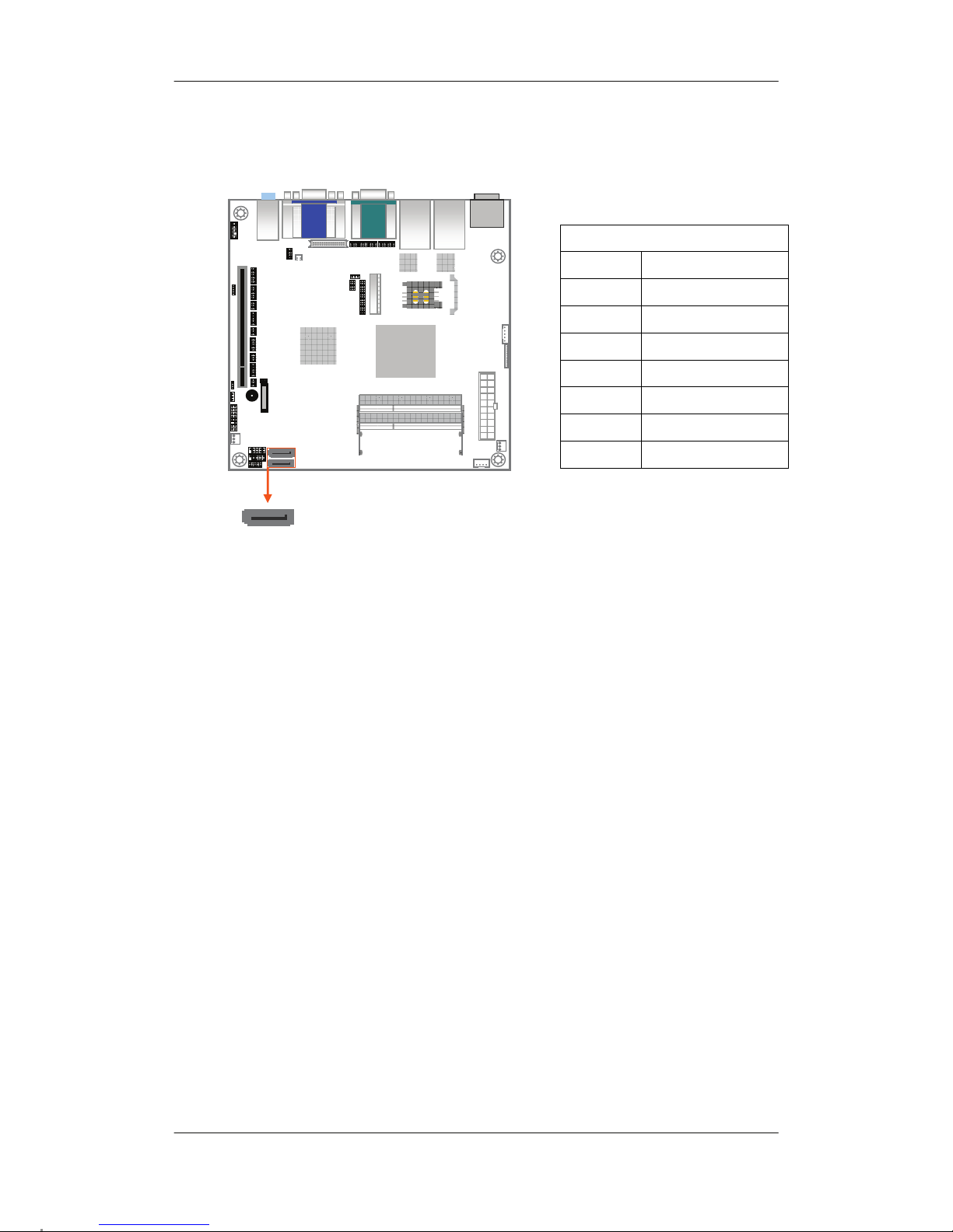
3.2.20 SMBUS Connector : CN_SMBUS1(Pitch 2.0mm)
3.2.21 CPU / SYSTEM FAN Power Connector :
CPUFAN1 / SYSFAN1
PIN NO. DESCRIPTION
1 V5S
2 SMBDATA
3 SMBCLK
4 GND
CPUFAN1
PIN NO. DESCRIPTION
1 GND
2 V12S
3 P1FAN
SYSFAN1
PIN NO. DESCRIPTION
1 GND
2 V12S
3 CSFAN
1
4
1
3
SYSFAN1
CPUFAN1
1
3
Page 37
Chapter 3 : Connectors
37
3.2.22 SATA Connector : SATA1~2
SATA1~2
PIN NO. DESCRIPTION
1 GND
2 TX+
3 TX-
4 GND
5 RX-
6 RX+
7 GND
1
7
Page 38
R-102 Series User’s Manual
38
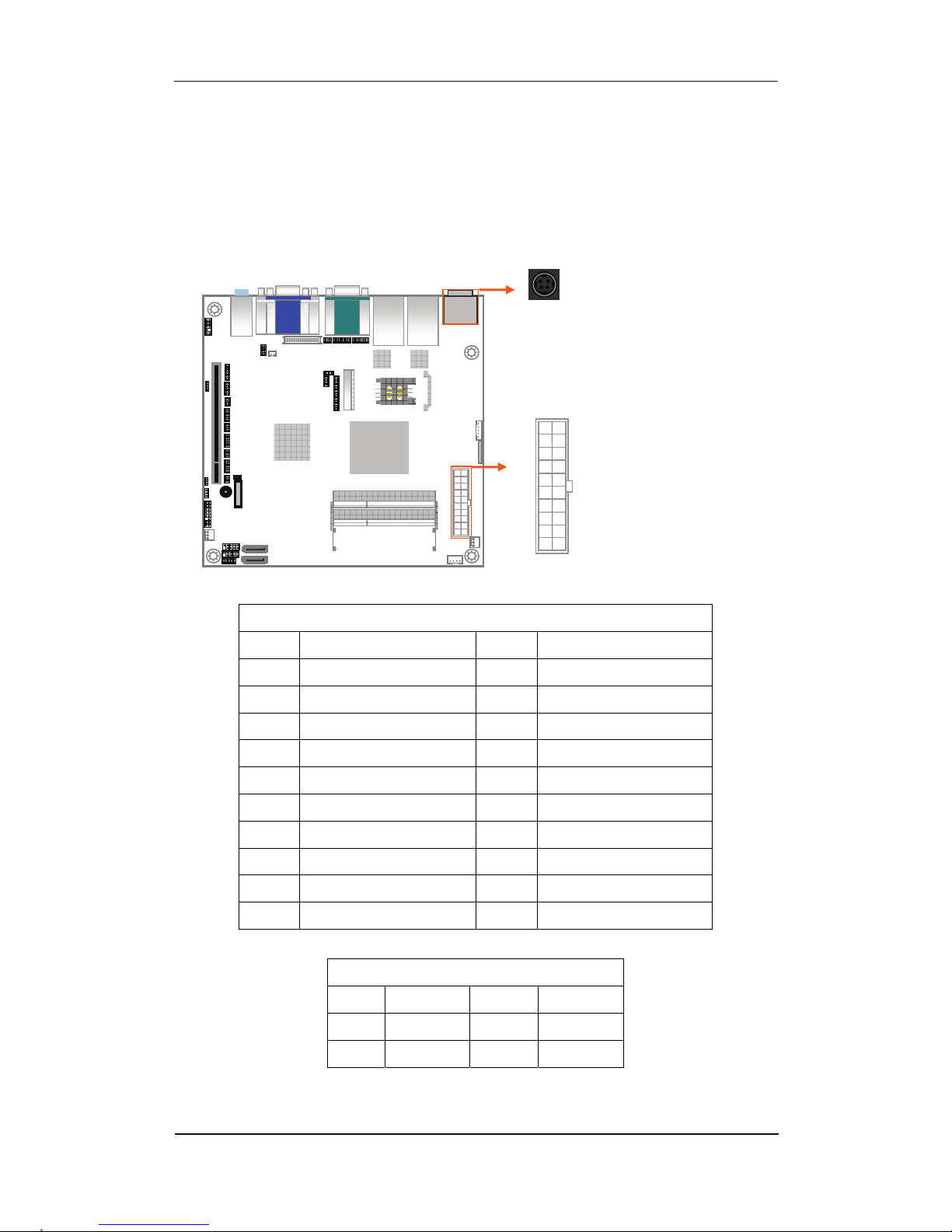
3.2.23 ATX / DC IN Power Connector : ATX1 / DC_IN1
“ATX1” and “DC_IN1” can input power at the same time (Dual Power Input), ATX1 will
have first priority. When use “DC_IN1” insert power adapter only, ATX1 can insert ATX power
cable to supply power for SSD or HDD.
ATX 1
PIN NO Definition PIN NO Definition
1
+3.3V
11
+3.3V
2
+3.3V
12
-12V
3
GND
13
GND
4
+5V
14
-PSON
5
GND
15
GND
6
+5V
16
GND
7
GND
17
GND
8
PW_OK
18
-5V (NC)
9
+5VSB
19
+5V
10
+12V
20
+5V
DC_IN1
PIN NO Definition PIN NO Definition
1 GND 3 VCC
2 GND 4 VCC
1
11
10
20
A
TX1
DC_IN1 (9~24V)
3
1
4
2
Page 39
Chapter 3 : Connectors
39
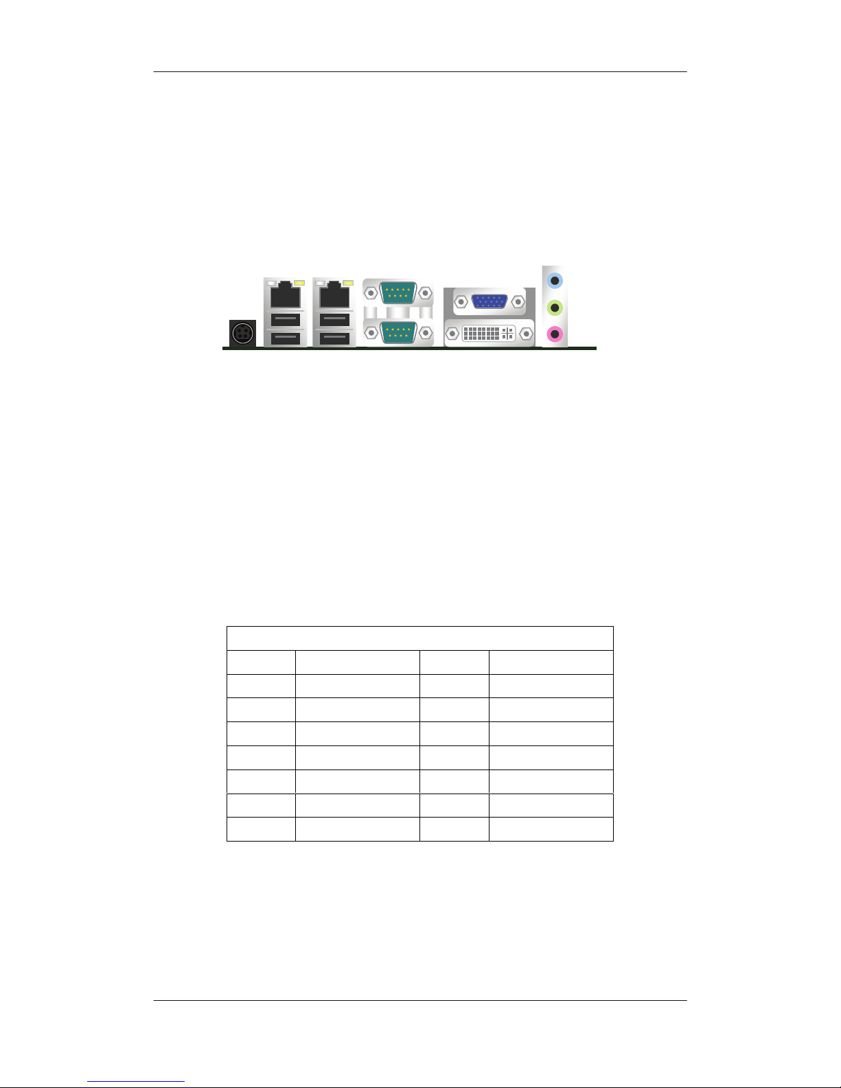
3.3 External Peripheral Interface Connector
Panel
3.3.1 Ethernet and USB 2.0 Connector
The R-102 is equipped with two built-in RJ-45 Ethernet controllers. Each
controller can connect to the LAN through one RJ-45 LAN connector.
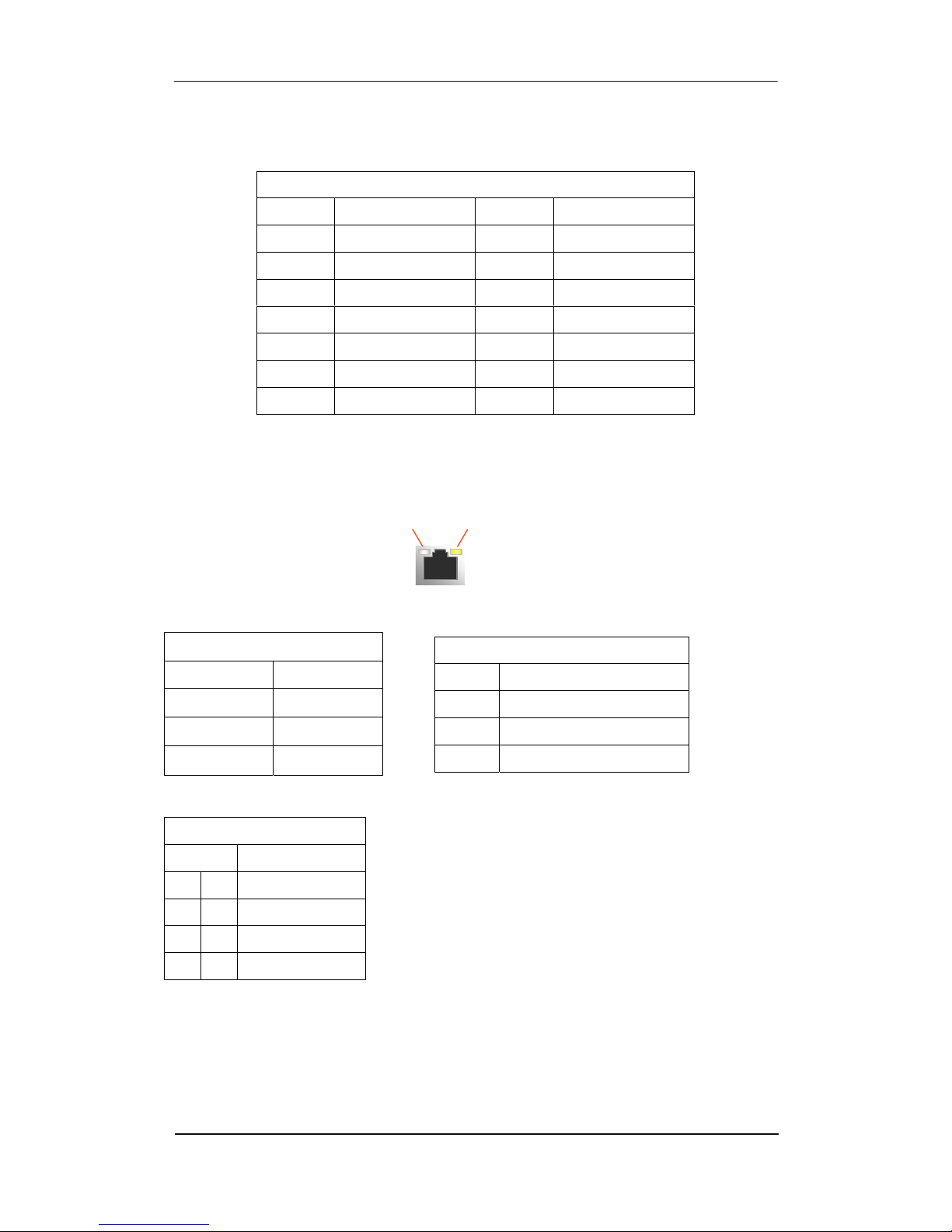
(R-102L-XX series : RJ45_1 only)
The RJ-45 Ethernet connector has two status LEDs, one green and one yellow.
The green LED indicates activity on the port and the yellow LED indicates the
speed.
RJ45_1
PIN NO. DESCRIPTION PIN NO. DESCRIPTION
L1 L18VSB L2 MDI00+
L3 MDI00- L4 MDI01+
L5 MDI01- L6 MDI02+
L7 MDI02- L8 MDI03+
L9 MDI03- L10 LANGND
L11 RACTLED0- L12 RLINK0
L13 RLINK1H0- L14 RLINK1G0-
USB_2
RJ45_1 RJ45_2
USB_1 COM2
COM1
CRT
DVI
A
UDIO_JACK1
CN_IN1
Page 40
R-102 Series User’s Manual
40
Activity/Link LED
Status Description
Off No Link
Blinking Data Activity
On Link
RJ45_2
PIN NO. DESCRIPTION PIN NO. DESCRIPTION
L1 L18VSB2 L2 MDI10+
L3 MDI10- L4 MDI11+
L5 MDI11- L6 MDI12+
L7 MDI12- L8 MDI13+
L9 MDI13- L10 LAN2GND
L11 RACTLED1- L12 RLINK1
L13 RLINK1H1- L14 RLINK1G1-
SPEED LED
Status Description
Off 10Mbps connection
Orange 100Mbps connection
Green 1Gbps connection
USB_1 / USB_2
PIN NO. DESCRIPTION
U1 U5 VCC
U2 U6 DATA0-
U3 U7 DATA0+
U4 U8 GND
A
CT/LINK
LED
SPEED
LED
Page 41
Chapter 3 : Connectors
41
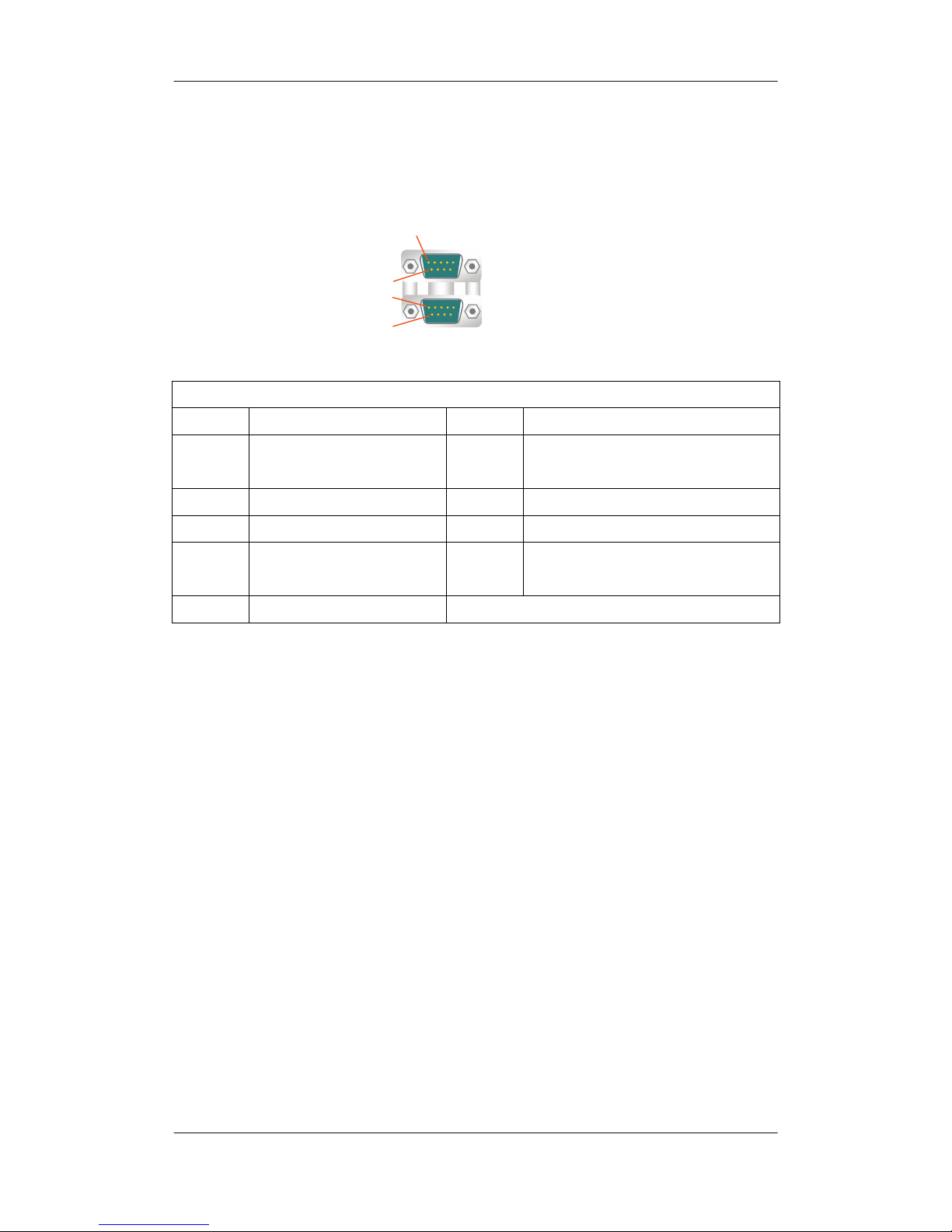
3.3.2 Serial Port Connector : COM1 / COM2
COM1 / COM2
PIN NO. DESCRIPTION PIN NO. DESCRIPTION
1 DATA CARRIER DETECT
(DCD#)
2 RECEIVE DATA (RXD)
3 TRANSMIT DATA (TXD) 4 DATA TERMINAL READY (DTR#)
5 GND 6 DATA SET READY (DSR#)
7 REQUEST TO SEND
(RTS#)
8 CLEAR TO SEND (CTS#)
9 RING INDICATOR (RI#)
1
6
1A
6A
Page 42
R-102 Series User’s Manual
42
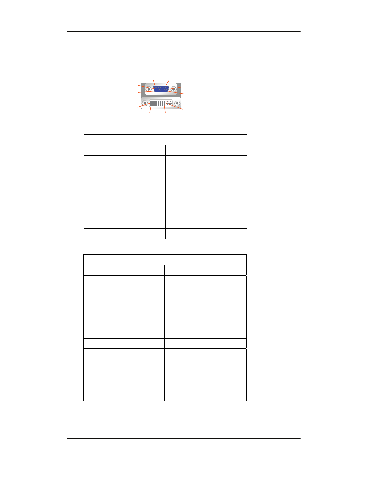
3.3.3 Display Connector : CRT / DVI
CRT
PIN NO. DESCRIPTION PIN NO. DESCRIPTION
1 RED 2 GREEN
3 BLUE 4 NC
5 GND 6 GND
7 GND 8 GND
9 V5S 10 GND
11 NC 12 5VCDA
13 5HSYNC 14 5VSYNC
15 5VCLK
DVI
PIN NO. DESCRIPTION PIN NO. DESCRIPTION
1 TMDS_TX2- 2 TMDS_TX2+
3 GND 4 NC
5 NC 6 DVI_SL
7 DVI_DA 8 NC
9 TMDS_TX1- 10 TMDS_TX1+
11 GND 12 NC
13 NC 14 V5S
15 GND 16 HPD
17 TMDS_TX0- 18 TMDS_TX0+
19 GND 20 NC
21 NC 22 GND
23 TMDS_TXC+ 24 TMDS_TXC-
5
10
15
6
1
11
9
17 24
16
1
8
Page 43
Chapter 3 : Connectors
43
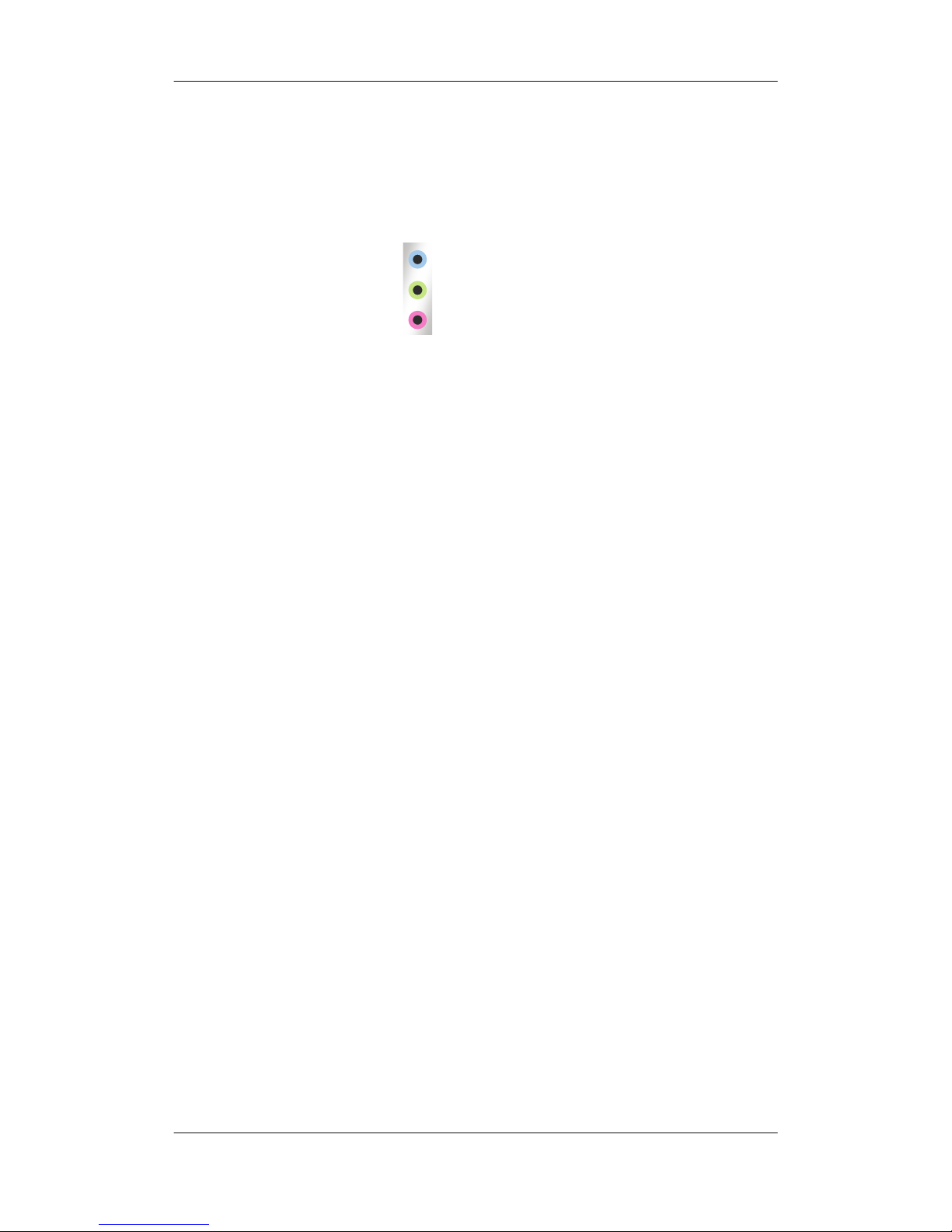
3.3.4 Audio Connector : AUDIO_JACK1
The audio jacks connect to external audio devices.
Line In port (Light Blue): Connects to a CD/DVD player or a musical
instruments..
Line Out port (Lime): Connects to a headphone or a speaker. With
multi-channel configurations, this port can also connect to front speakers.
Microphone (Pink): Connects a microphone.
LINE IN
LINE OUT
MIC
Page 44

R-102 Series User’s Manual
44
Chapter 4 : Installation
4.1 Before Installation
For installation, you may need tool (screwdriver).
Users must follow these guidelines to ensure the motherboard is protected
during installation.
Make sure your computer is powered-off whenever work in with inside
components.
The motherboard, like all other electronic equipment, is sensitive to static.
Please take the proper precautions when handling it. If possible, ground
yourself by touching a metal table or desk. Keep the board in its conductive
wrapping until it is configured and ready to be installed in your system.
Keep all magnets away from both your hard disks, especially magnetic
screwdrivers. Keep hard disks apart if disassembled.
Keep water and liquids away from your computer and its components
Page 45
Chapter 4 : Installation
45
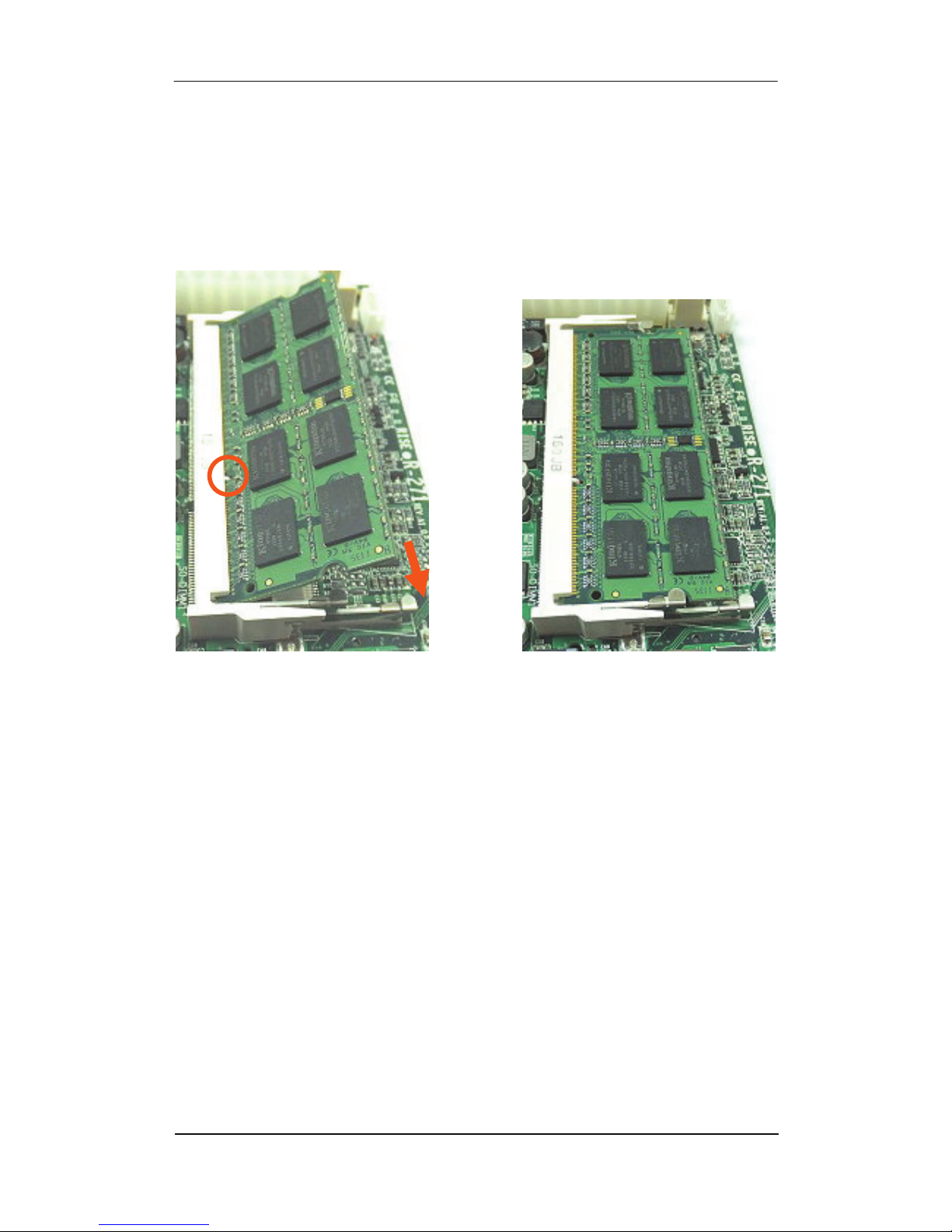
4.2 Install the SO-DIMM DDR3 RAM
Step 1: Locate the SO-DIMM socket. Place the board on an anti-static mat.
Step 2: Align the SO-DIMM with the socket. Align the notch on the memory
with the notch on the memory socket.
Step 3: Insert the SO-DIMM. Push the memory in at a 20º angle.
Step 4: Seat the SO-DIMM. Gently push downwards and the arms clip into
place.
(ATOM N2600 only support one memory module, SO-DIMM 2 slot.)
(When you install only one memory module, install it on SO-DIMM 2 slot.)
Page 46

R-102 Series User’s Manual
46
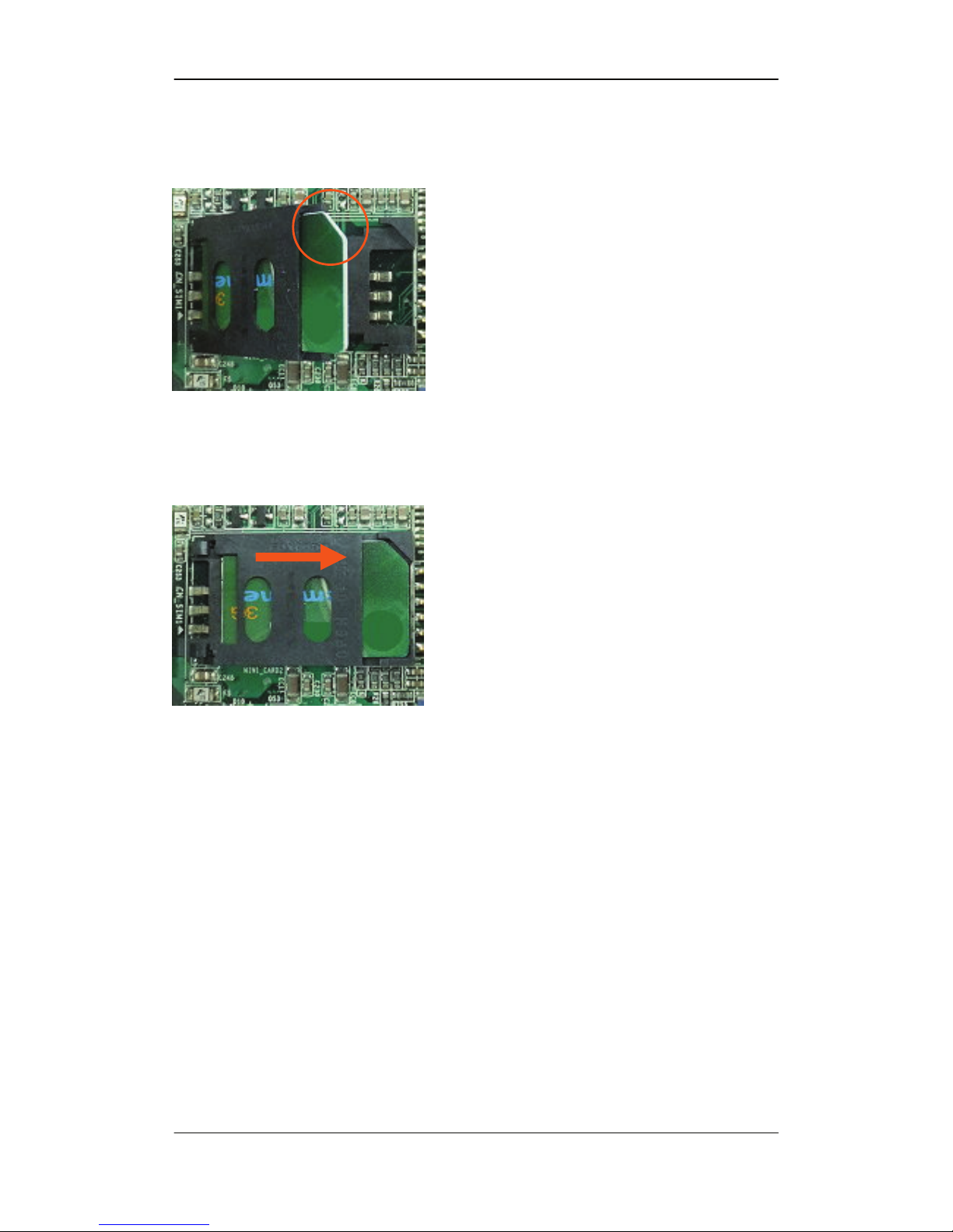
4.3 Install the SIM card
Step1 : Follow arrow direction, slide the cap toward OPEN.
Step2 : Make sure that the cap is now at the OPEN position.
Step3 : Flip the cap up for inserting a SIM card into.
Page 47
Chapter 4 : Installation
47
Step4 : Insert a SIM card as shown in the photo.
Be sure that the corner cut is on top and the golden pads are up.
Step5 : Flip down the cap, press down and slide the cap to the CLOSE
position. Be sure that the cap is tightly held with the socket.
Page 48
R-102 Series User’s Manual
48
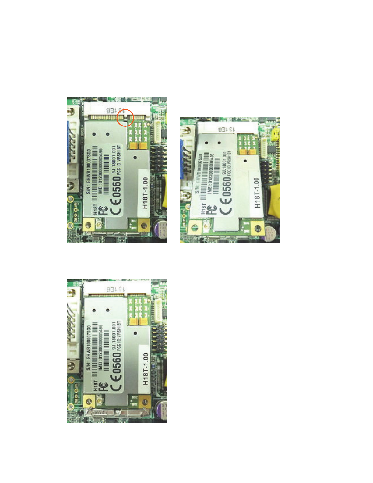
4.4 Install the Mini PCI-E card
Step 1: Align the mini pci-e card with the socket.
Align the notch on the mini pci-e card with the notch on the mini pci-e socket.
Step 2: Seat the MINI PCI-E card. Gently push downwards and the arms clip
into place.
Page 49
Chapter 5 : BIOS Setup
49
Chapter 5 : BIOS Setup
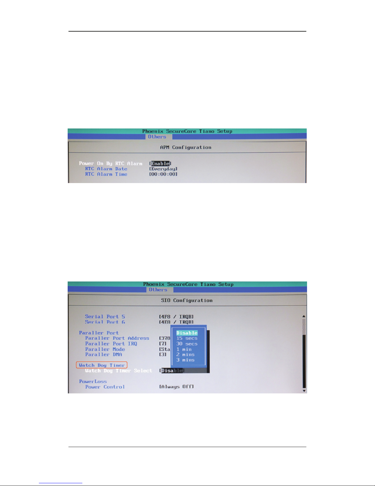
5.1 APM :
The APM is for setting power on date/time.
When power on press < F2 > into Phoenix SecureCore Tiano setup.
Move to [ Others -> APM Configuration ], press Enter.
5.2 Programming Watch Dog Timer :
The watchdog timer makes the system auto-reset while it stops to work for a
period.
The integrated watchdog timer can be setup as system reset mode by program.
Move to [ Others -> SIO Configuration -> Watch Dog Timer ] , press Enter.
Page 50
R-102 Series User’s Manual
50
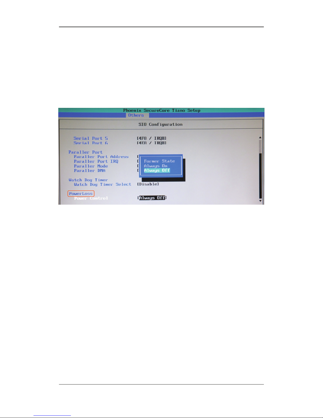
5.3 Power Loss :
The power loss is boot up mode selection by firmware
(Jumper CN_AT1 is hardware)
Always on = AT mode (auto boot up), Always off = ATX mode (boot up by
power button). Move to [ Others -> SIO Configuration -> PowerLoss ] , press
Enter.
Page 51

Chapter 5 : BIOS Setup
51
5.4 Flash BIOS :
5.4.1 Flash Tool
The board is based on Phoenix BIOS and can be updated easily by the BIOS
auto flash tool.
File name of the tool is “pflash.exe”, it’s the utility that can write the data into
the BIOS flash ship and update the BIOS.
5.4.2 Flash BIOS Procedure
1. Please make a bootable disk.
2. Get the last .bin files you want to update and copy it into the disk.
3. Copy “pflash.exe” and “Efildr16” to the disk.
4. Power on the system and flash the BIOS under the DOS environment.
( Example: ’’pflash_/cvar_/bbl_/sa_/silent_xxx.bin’’ )
Note: a. _ Underscore means Space
b. xxx.bin means the BIOS file that you want to update
5. The system will auto re-boot after finish update.
6. Please turn off the system and clean CMOS by Jumper.
7. Restart the system.
Any question about the BIOS re-flash please contact your distributors
 Loading...