

Page 1
WARNING!
Standard Scoop Configuration With:
Water Bypassing the Filter, %
Cotton Filter (KF-1053)
0.00
(MUST READ PRIOR TO INSTALLATION)
I. Water Ingestion Disclaimer:
This product is intended for general highway use only! Under normal driving conditions water ingestion is usually not
an issue; however, if the product becomes submerged from rain splashes or mud puddles due to harsh rains or
flooding the engine may ingest water which could cause severe engine damage. Do NOT use this product when
crossing any body of water including but not limited to large puddles, streams, rivers or lakes. S&B has conducted
extensive water testing with Southwest Laboratories to design a product, which was engineered to
protect your vehicle. The testing was done at 700 CFM and according to the SAE J2554, Engine intake Air
Water Separation Test Procedure that has been attached and can also be found on our website.
If your engine ingests water, this could cause severe engine damage by hydro-lock or other conditions. Care should be
taken to avoid these driving conditions. ENGINE DAMAGE CAUSED BY THE INGESTION OF WATER INTO THE
ENGINE IS THE DRIVER’S RESPONSIBILITY AND IS NOT COVERED BY S&B FILTERS!
The table below demonstrates what percentage of the water bypassed the filter during the SAE J2554 Test Procedure.
Visit www.sbfilters.com to see the entire Test Report and learn more about this product.
II. Scoop Obstruction:
Regularly inspect the entire Scoop Inlet for any obstruction or debris that may impede the flow of air.
III. Decreased Ride Height
Once the Scoop has been installed, please be aware that the Scoop sits lower than the bumper and drive accordingly
to avoid damage to the scoop or vehicle. Make sure there is plenty space between your tire and the scoop before
driving. The scoop system may not work with aftermarket wheels and tires.
Ride height with this scoop installed is decreased by 2.0” on the passenger side.
IV. Do NOT Seal Off Stock Inlet Location:
In addition to pulling air from the base of the air box, the S&B Cold Air Intake Kit pulls air from the same location as
the stock induction system. UNDER NO CIRCUMSTANCE SHOULD YOU SEAL OFF THIS AIR INLET. Doing so
could result in severe injury or death or damage to the vehicle or property. Sealing off the stock air inlet could cause a
significant vacuum should the Scoop become partially or completely obstructed which among other things could pull oil
into intake tube leading to an explosion and/or a run-away truck condition as the oil would serve as fuel to the engine.
V. Warranty for Scoop & Filter Wrap
S&B provides a limited warranty to guarantee the product is free of material and workmanship defects. Any product will be
replaced upon identification of such defect. Normal wear and tear is not covered under this warranty. Final authorization is at the sole
discretion of S&B Filters, Inc.
VI. How long will the Scoop & Filter Wraps Repel Water?
The Scoop & Filter Wraps are specially treated to repel water. The water repellency longevity is dependent upon driving conditions
and the number of times the filter is cleaned. Generally speaking, we recommend changing the Filter Wrap every 6-12 months.
However, a quick test can determine if it is time to change your Filter Wrap. Simply take an ordinary clean spray bottle filled with water
and gently spray the Filter Wrap. If the water beads off the Filter Wrap, your water repellency is still working. If you see water enter
through the Filter Wrap, it is time to purchase a new Filter Wrap.
15461 Slover Ave., Fontana, CA 92337 - Phone: (909) 947-0015 - Fax: (909) 947-0603 - www.sbfilters.com 1
Page 2
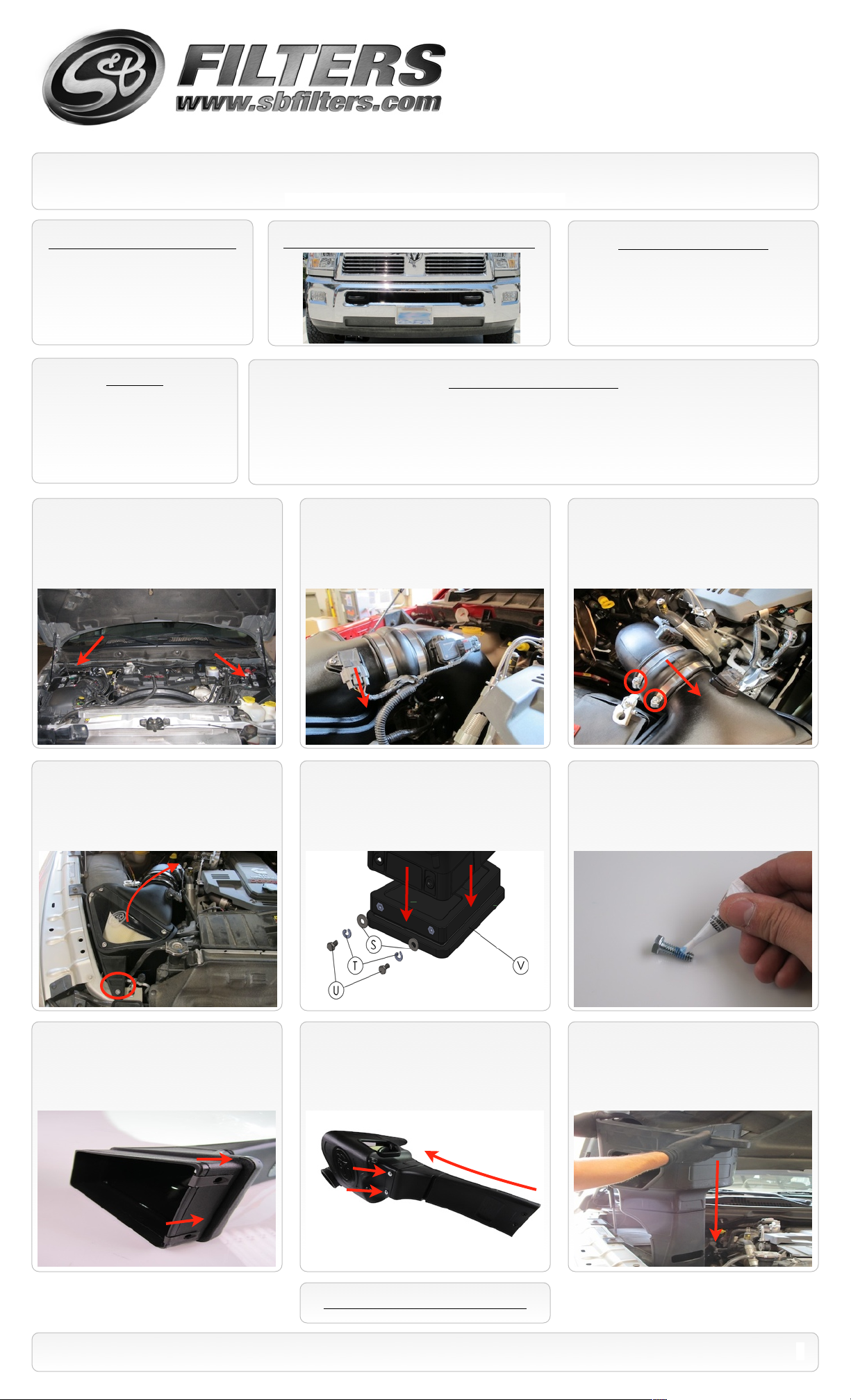
INSTALLATION INSTRUCTIONS
P/N: AS-1002
Important: Read warning page prior to proceeding.
VEHICLE APPLICATION
Year: 2010-12
Make: DODGE
Model: RAM 2500/ 3500
Engine: 6.7L DIESEL
(Factory bumper only)
NOTES
Kit may not fit with the following:
Aftermarket Bumper
•
Body Lift or Lowering Kit
•
Front Hitch
•
Oversized Wheels and Tires
•
1. With the ignition switched off and the
parking brake set, disconnect the negative
battery cables on both batteries.
STANDARD FACTORY BUMPER ONLY
TOOLS REQUIRED
8mm Socket
•
18mm Wrench or Deep Socket
•
7/16” & 1/2” Wrench & Socket
•
5/16” Nut Driver or Flat Blade Screwdriver
•
BEFORE YOU START
Please read the entire product guide before proceeding.
•
Ensure all components listed on page 4 are present.
•
If you are missing any of the components, call our customer support at (909) 947-0015.
•
Do not attempt to work on your vehicle while engine is hot.
•
Make sure the engine is turned off and the vehicle is in Park or the Parking Brake is set.
•
2. Disconnect the IAT sensor wiring
harnesses from the sensor.
3. Loosen both the #72 Hose Clamps on
the Hump adapter, then slide the hump
adapter over the Filter adapter tube.
4. Remover the M8x1.25x40mm Allen Head
screw from the air box and remove the
complete air box assembly from the truck.
7. Slide the Speed Clip Nuts (C) over the
flange of the Scoop Channel (D). Make sure
the nuts clip into place.
5. If installed, remove the S&B Box plug
from the lower portion of the air box using
7/16” socket. Retain plug and all hardware if
you expect on driving through heavy rain or
snow.
8. Secure the Channel assembly to the air
box using the supplied 1/4”-20 Screws (B),
1/4” Split Lock washers (K), and 1/4” Flat
Washers (A).
6. Apply a small amount of the supplied Blue
Loctite to all (6) 1/4”-20 Hex Bolts (B).
9. Slide the air box/ channel assembly down
from the engine compartment and set the air
box back into the two factory grommets on
the side of the battery tray.
SEE EXPLODED VIEW ON PAGE 5
15461 Slover Ave., Fontana, CA 92337 - Phone: (909) 947-0015 - Fax: (909) 947-0603 - www.sbfilters.com
2
Page 3

INSTALLATION INSTRUCTIONS (continued)
P/N: AS-1002
10. Reinstall the Socket pan head screw
removed in Step #4.
13. From under the truck using 18mm
socket, remove the nut behind the bumper.
11. Install the four supplied Speed Clip Nuts
(C) over the flange of the Scoop Base (E).
Make sure the outside tabs snap into the
holes.
14. Slide the Scoop base assembly up into
the Scoop Channel (D) and slide the
mounting bracket (H) over the stud behind the
bumper.
12. Install the Mounting bracket (H) to the
top of the Scoop Base (E) using two 5/16”-18
Hex Bolts (G), two 5/16” Hex Nuts (H), and
four Flat Washers (F). Leave hand tight for
now.
15. On the backside of the assembly,
secure the Scoop Base to the Channel using
the two 1/4”-20 Screws (B), 1/4” Split Lock
washers (K), and 1/4” Flat Washers (A).
16. On the frontside of the assembly,
secure the Scoop Base to the Channel using
the two 1/4”-20 Screws (B), 1/4” Split Lock
washers (K), and 1/4” Flat Washers (A).
19. Check to make sure the Scoop
assembly does not interfere with the wheel or
wheel well liner. Turn the wheel in both
directions while trying to simulate full
suspension travel.
17. When you are satisfied with the
positioning, tighten down the Mounting
bracket (H) to the Scoop Base (E) using two
1/2” wrenches (one on top and one inside).
20. Inspect the entire installation, be sure
the kit is properly positioned and all fasteners
are secure.
18. Reinstall the nut behind the front bumper
securing the Mounting bracket (H). Torque to
factory specs.
21. Reinstall IAT sensor connection and
hump adapter. Tighten both #72 hose clamps.
Reconnect both batteries terminals. The
installation is now complete.
See warnings on Page #1.
SEE EXPLODED VIEW ON PAGE 5
15461 Slover Ave., Fontana, CA 92337 - Phone: (909) 947-0015 - Fax: (909) 947-0603 - www.sbfilters.com
3
Page 4

Scoop Plug Installation
P/N: AS-1002
When to use the plug.
We recommend installing the plug during the winter months if you in an area that receives snow or excessive rain.
1. From under the truck using 18mm
socket, remove the nut behind the bumper.
Slide the mounting bracket off the stud.
Then re-attach the nut and torque to factory
specs.
2. On the backside of the assembly, remove
the two 1/4”-20x1.0” Screws (B), 1/4” Split
Lock washers (K), and 1/4” Flat Washers (A)
mounting Scoop base to the channel.
4. Install the Plug (L) into the Scoop
Channel using the two 1/4”-20x3/4” Screws
(M), 1/4” Split Lock washers (K), and 1/4” Flat
Washers (A).
3. On the frontside of the assembly, remove
the two 1/4”-20x1.0” Screws (B), 1/4” Split
Lock washers (K), and 1/4” Flat Washers (A).
SEE EXPLODED VIEW ON PAGE 5
15461 Slover Ave., Fontana, CA 92337 - Phone: (909) 947-0015 - Fax: (909) 947-0603 - www.sbfilters.com
4
Page 5

ITEM
QTY.
DESCRIPTION
P/NA8
Washer, 1/4”ID x 5/16”OD
AI1073-00
B6Hex Head Screw, 1/4”-20x1.0”
AI1131-00
C6Speed Clip Nut, 1/4-20
AI1059-00
D1Scoop, Main Channel
AL1164-00
E1Scoop, Base
AL1165-00
F4Washer, Flat USS, 5/16”ID
AI1093-00
G2Hex Head Screw, 5/16”-18x3/4”
AI1467-00
H1Lower Mounting Bracket
AI1543-00
I2Nut, Hex Nylock, 5/16”-18
AI1298-00
J1Loctite 242, .02oz., Blue
AI1406-00
K8Washer, Split Lock, 1/4”
AI1309-00
L1Scoop, Plug
AL1166-00
M2Hex Head Screw, 1/4”-20x3/4”
AI1068-00
N
EXPLODED VIEW
P/N: AS-1002
Plug Kit
PERFORMANCE TESTING
Engage parking brake and start your engine.
•
Listen for abnormal noises. If an air leak is
detected, re-inspect hoses and connections as
they may need to be repositioned and
tightened.
S&B FILTERS recommends that you keep
•
your OE intake system in the event it is
required in the future.
In order to maintain your warranty, all
•
connections and components must be
checked periodically for alignment and for
proper tension on all connections. Failure to
do so may void your warranty.
Use only S&B FILTERS cleaning and oil
•
products to service your filter. Using any other
brand oil and or cleaners on your S&B air filter
may void your warranty.
RELATED ITEMS FOR YOUR
PURCHASE
Air Filter Wrap (S&B P/N: WF-1032)
AM0177-00 Rev.B 04/29/13
15461 Slover Ave., Fontana, CA 92337 - Phone: (909) 947-0015 - Fax: (909) 947-0603 - www.sbfilters.com
•
5
 Loading...