

Page 1
Installation Instructions
P/N: 76-1010 / 76-1010B
Vehicle Application
Year: 2005-07
Make: Ford
Model: F-Series
Engine: 6.0L V8
Ratchet and extensions
•
8mm, 10mm, 7/16” Wrench & Deep Socket
•
3/16” Hex Drive
•
Torque Wrench (in.lbs.)
•
Teflon tape
•
Tools Required
Before You Start
Please read the entire product guide before proceeding.
•
Ensure all components listed on page 4 are present.
•
If you are missing any of the components, call our customer support at (909) 947-0015.
•
Do not work on your vehicle while engine is hot.
•
Make sure the engine is turned off and the vehicle is in Park or the Parking Brake is set.
•
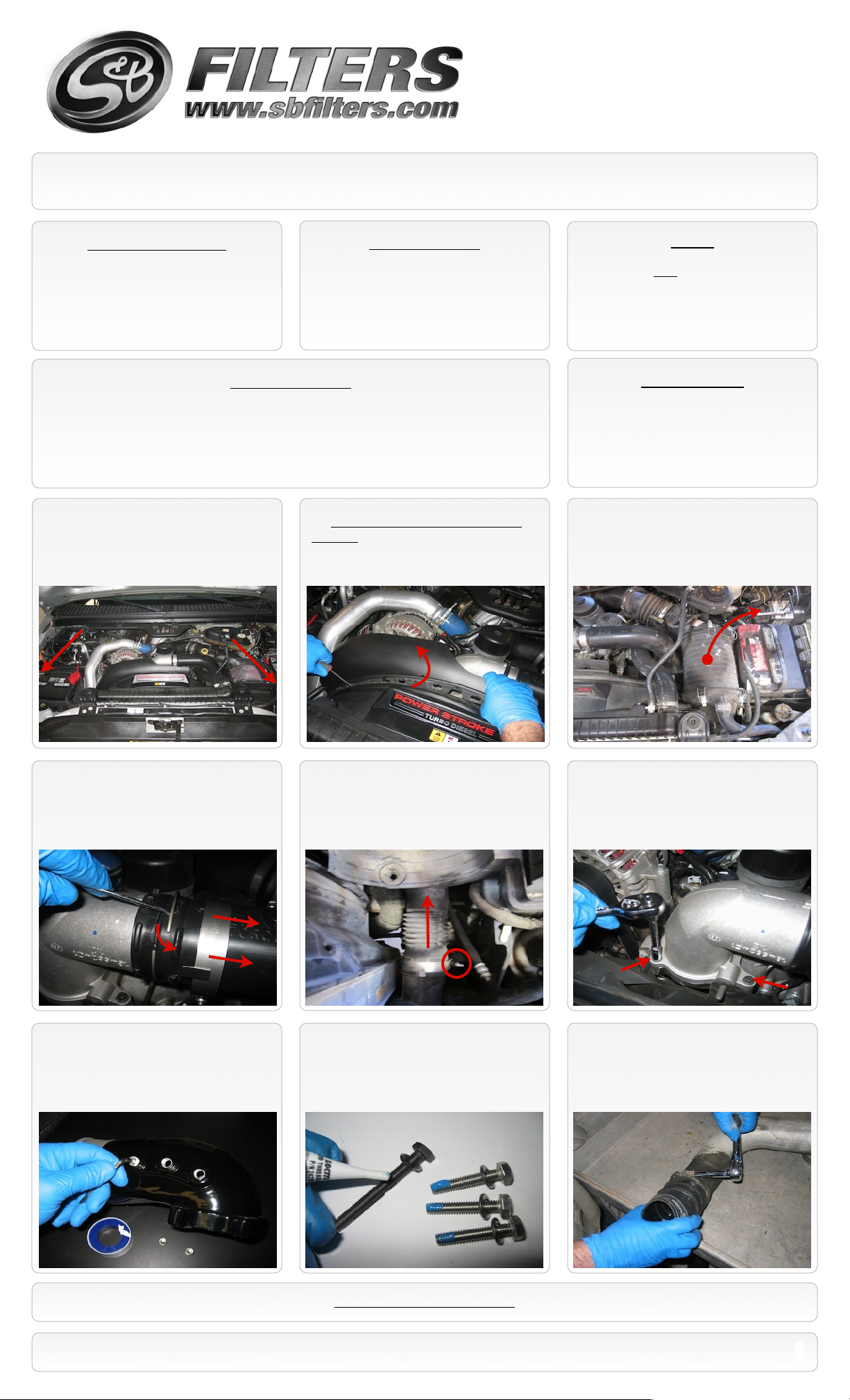
1. With the ignition switched off and the
parking brake set, disconnect the negative
battery cables on both batteries.
2. Optional step, to allow better access to
the elbow. Use a small flat head screwdriver
and pry the clips open and pull up working
your way across to remove the upper fan
shroud.
Notes
All required torque specs. are called out in
•
Inch pounds NOT foot pounds.
Installation will take approx. 1hr. to
•
complete.
Related Items
Available at www.sbfilters.com
S&B Cold Air Intake Kit (Oiled filter)
•
(S&B P/N: 75-5032)
S&B Cold Air Intake Kit (Dry filter)
•
(S&B P/N: 75-5032D)
3. Remove the OE (or aftermarket) intake to
gain access to the clamps of the OE boost
tube. Follow the manufactureʼs procedures
for removing the intake.
4. Loosen the upper hose clamp at the OE
elbow and pry the compression clip out of the
groove.
7. Apply sealant (Teflon tape) to each
1/8”NPT plugs (G) and insert the plugs into
the ports you will not use on the elbow. Use
3/16” Hex drive and torque the plugs to 40
In.lbs.
5. Loosen the hose clamp at the intercooler
lower flange and remove the OE boost tube
from the vehicle along with clamps. Remember
how this is removed because it will have to be
repeated to install the new one.
8. Place 6mm Washer (D) over each of the
M6x30mm Bolts (F) and one over the
M6x93mm Bolt (E), next apply a small
amount of the supplied thread locker to each
of the bolts.
6. Remove the 4 bolts that secure the OE
elbow to the intake manifold and remove the
elbow from the vehicle. Be careful not to let
debris fall into the intake manifold.
9. Remove the other clamp from the OE
boost tube. Clean the two clamps as they will
both be re-used on the lower connection of
the new tube.
SEE EXPLODED VIEW ON PAGE 3
15461 Slover Ave., Fontana, CA 92337 - Phone: (909) 947-0015 - Fax: (909) 947-0603 - www.sbfilters.com
1
Page 2
Installation Instructions (continued)
P/N: 76-1010 / 76-1010B
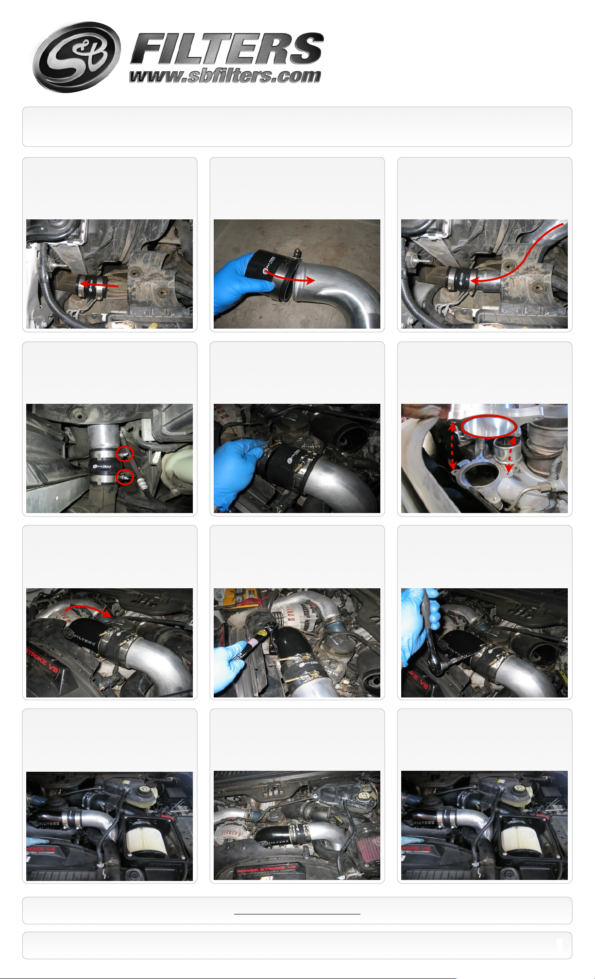
10. Place the 2 OE clamps over the Hump
Coupler (K) and slide the coupler over the
lower flange of the intercooler.
13. Position the OE clamps and torque
them to 106 In.lbs.
11. Place one the supplied T-bolt camps (I)
over the Straight Coupler (H) and slide it on
the upper end (Large diameter) of the Boost
Tube (J).
14. Place the other supplied T-bolt clamp (I)
over the end of the Straight coupler (H).
12. Snake the Boost tube assembly into
position and into the Hump coupler (K).
15. Clean the intake manifold surface. Then
install the Billet Spacer (A) and the O-ring (B)
onto the intake manifold using 3 supplied
M6x30mm bolts (F) and 6mm washers (D).
Torque to 100 In.lbs.
16. Install the other O-ring (B) in the top
groove of the Billet Spacer (A). Insert the S&B
Elbow (C) into the Straight coupler (H) and
align the mounting holes with the Billet
spacer. Be sure both mating surfaces are
clean.
19. Reinstall the Intake or OE air cleaner
and filter removed in Step 3.
17. Insert the M6x30mm Bolts (F) and
M6x93mm Bolts (E) in the proper locations
and torque to 100 In.lbs.
20. Align the upper fan shroud and snap it
back into place if it was removed.
18. Position the upper T-bolt clamps as to
not hit the hood when closed and torque them
both to 90In.lbs.
21. Reconnect both batteries. Inspect your
installation, make sure the elbow and boost
tube is properly positioned and all fasteners
are secure. The installation is now complete.
SEE EXPLODED VIEW ON PAGE 3
15461 Slover Ave., Fontana, CA 92337 - Phone: (909) 947-0015 - Fax: (909) 947-0603 - www.sbfilters.com
2
Page 3

Installation Instructions (continued)
P/N: 76-1010 / 76-1010B
ITEM
QTY.
DESCRIPTION
P/NA1
Billet Spacer Block
AL1208-00
B2O-Ring
AI1591-00
C1Intake Elbow, White or Black
AL1099-00
D7Washer, S.S. Flat, 6mm
AI1416-00
E1M6-1.0x93mm, Hex Head Screw
AI1413-00
F6M6-1.0x30mm, Hex Head Screw
AI1414-00
G3Plug, Socket, 1/8”NPT
AI1398-00
H1Coupler, Silicone 3.5”IDx3.25”
AI1394-00
I2T-bolt Clamp, 92.2-100mm
AG1027-00
J1Boost Tube, Alum.
AL1102-00
K1Coupler, Hump Silicone 3”IDx4”
AI1395-00
AM0195-00 Rev.A 02/05/13
Testing and Maintenance
Engage parking brake and start your engine. Listen for abnormal noises. If an air leak is
•
detected, re-inspect hoses and connections as they may need to be repositioned and
tightened.
S&B Filters recommends that you keep your OE intake system in the event it is required in
•
the future.
In order to maintain your warranty, all connections and components must be checked
•
periodically for alignment and for proper tension on all connections every 6-12 months.
Failure to do so may void your warranty.
Use only S&B FILTERS cleaning and oil products to service your filter. Using any other
•
brand oil and or cleaners on your S&B air filter will void your warranty.
Emissions Standard
The California Air Resource Board (CARB) requires that an E.O. identification label be applied to the vehicle in order to pass a smog check inspection when a
Performance Intake Kit has been installed. You must place the E.O. label provided on or near the intake kit after installation so that a smog check technician can
easily verify the E.O. number. As of April 2009, S&B has never had a product where CARB denied an exemption request; however, the exemption process with
CARB can take as long as 18 months. Check the status of the exemption process by looking up a specific part number at www.sbfilters.com. The CARB Exemption
number and/or status is listed under the Product Details section for each part number. If the status shows as “Pending,” CARB has yet to issue an exemption.
Products that have not been issued an EO number are street legal in most states, but may not be used on emission controlled vehicles in the state of California and
are for off road use only. If you purchased your kit from S&B Filters directly, we will automatically mail you your Exemption Sticker when it is issued to us. If you
purchased your kit from an authorized S&B Filters Dealer, log onto our web site and register to receive your Exemption Sticker.
Warranty
Visit www.sbfilters.com/Support/Why-S-B/Million-Mile-Limited-Warranty for S&B Filterʼs complete warranty.
15461 Slover Ave., Fontana, CA 92337 - Phone: (909) 947-0015 - Fax: (909) 947-0603 - www.sbfilters.com
3
 Loading...