

Page 1
INSTALLATION INSTRUCTIONS
INSTALLATION INSTRUCTIONS
S&B P/N 75-9006
1988-1995
Toyota
Pickup, 4 Runner
3.0L V6
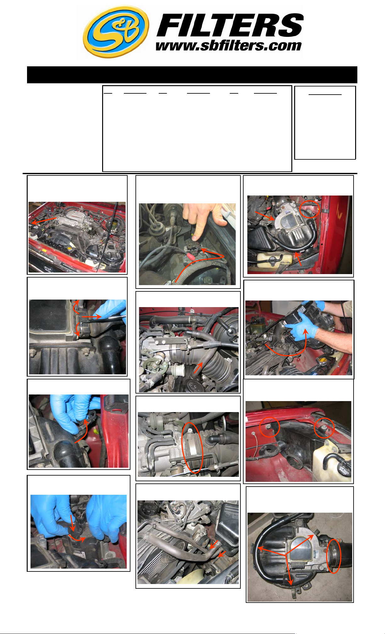
1. With the ignition switched off and the
vehicle placed in park and or the parking
brake set, disconnect the negative battery
terminal.
Qty Parts List Qty Parts List Qty Parts List
1 Intake Tube 4 10-24 Screws 1 1/2” x 7” Hose
1 Air Box 8 #10 Washers 3 1/4” Hex Head Screws
1 Air Filter 4 10-24 Nylock Nuts 3 1/4”-20 Nylock Nuts
1 Clear Lid 1 3/8”-90 degree Hose Barb 6 1/4” Washers
1 2.75” x 2” Adapter 1 5/8” x 1/2” Hose Barb 1 Zip Tie
2 #44 Hose Clamp 1 3/8”x1/4” NPT Hose Barb 5 SS Pan Head Screws
1 Steel Ring Adapter 1 Angled Bracket 5 SS Sealing Washers
1 Ring Gasket 1 Straight Bracket 1 CARB Sticker
5. If your vehicle model has the ignition coil
wiring harness routed over the intake system then you will need to disconnect it from
the coil as well.
Tools Needed
3/8" Socket and Wrench
Flat Head Screwdriver
Phillips Head Screwdriver
10mm Socket or Wrench
12mm Socket
Socket Extension
9. Unbolt the three bolts that secure the OE air
box assembly to the inner fender.
2. Use a small screwdriver or scribe and
unclip the safety wire, then disconnect the
electrical connection from the MAF sensor.
3. Unclip the wiring harness from the OE air
box assembly.
6. Disconnect the CCV line from the driver
side valve cover.
7. Loosen the OE hose clamp at the throttle
body.
10. Slide the OE intake tube off the throttle
body then pull up and out on the air box
assembly to remove it from the vehicle.
11. Remove the two bolts the secure the restrictive OE air inlet duct to the vehicle and
remove the duct.
4. Push down to unclip then disconnect
the coil wire from the ignition coil.
9/18/2008
REV-B
8. Disconnect the vacuum hoses from the OE
air box assembly.
12. Loosen the OE hose clamp at the MAF
sensor and unclip the three clamps and separate the upper half of the air box from the assembly.
787 S. Wanamaker Ave, Ontario, CA 91761
(909) 947-0015 Phone • (909) 947-0603 Fax
www.sbfilters.com
(Over)
Page 2
INSTALLATION INSTRUCTIONS (continued)
INSTALLATION INSTRUCTIONS (continued)
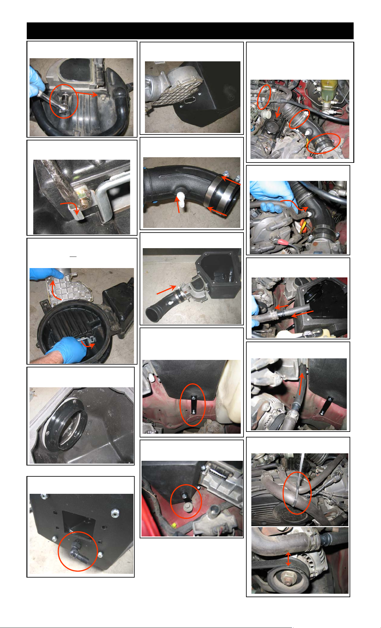
13. Remove the two outside nuts that secure
the MAF sensor to the air box lid.
14. Turn the lid over and use a screwdriver to
bend the safety tabs away from the inside
nuts. Then remove the nuts.
17. Install the MAF sensor to the S&B air box
use the OE gasket and nuts, we suggest that
you apply thread lock to the studs.
18. Thread the straight hose barb into the
S&B tube then attach the coupler with the
hose clamp.
22. Loosen the OE hose clamp and separate
the upper OE intake tube from the OE resonator. Use this tube to connect the S&B intake tube to the throttle body, secure all hose
clamps. Then reconnect the CCV line to the
valve cover.
23. Connect the smaller of the two OE vacuum lines to the hose barb on the S&B tube.
15. Pull the MAF sensor out of the air box lid
while unclipping the venturi ring from the inside
of the lid. You will not
spacers when installing the MAF sensor to the
S&B air box.
16. Install the ring adapter to the inside of the
S&B air box use the supplied gasket and hardware.
reuse the venturi or the
19. Attach the tube assembly to the MAF
sensor, leave loose for alignment.
20. Place the air box assembly into the vehicle use the straight bracket at the lower box
mount and use the supplied 1/4” hardware to
secure it to an unused hole in the inner
fender.
24. Insert the 5/8” to 1/2” hose barb into the
larger OE vacuum line then insert the barb
into the supplied 1/2” x 7” piece of hose.
25. Attach the new vacuum line to the 90
degree hose barb on the S&B air box.
16. Thread the 90 degree hose barb into the
S&B air box, careful not to cross thread.
9/18/2008
REV-B
21. Use the angled bracket on the upper air
box mount and secure it to the inner fender
with the OE hardware.
787 S. Wanamaker Ave, Ontario, CA 91761
(909) 947-0015 Phone • (909) 947-0603 Fax
www.sbfilters.com
26. Use the supplied Zip-Tie and secure the
vacuum line away from the alternator pulley.
Page 3

7
INSTALLATION INSTRUCTIONS (continued) INSTALLATION INSTRUCTIONS (continued)
27. Reconnect the MAF sensor electrical
connection.
28. Reconnect the coil wire to the ignition coil.
And electrical connections if removed.
29. Install the S&B filter into the S&B air box as
shown below.
30. Reconnect the battery ,Inspect your installation, make sure kit is properly positioned and
all fasteners are secure.
31. Affix the C.A.R.B. sticker in plain sight
under the hood near the intake system. Your
installation is now complete.
Smog Certification Note:
The California Air Resource Board
(CARB) requires that an E.O.
identification label be applied to the
vehicle in order to pass a smog
check inspection when a High
Performance Intake Kit has been
installed.
You must place the E.O. label
provided on or near the intake kit
after installation so that a smog
check technician can easily verify
the E.O. number.
28. Secure the filter to the flange with the hose
clamp.
29. Place the clear lid on the S&B air box and
use the supplied SS hardware to secure.
PERFORMANCE TESTING
∗ Engage parking brake and start your
engine. Listen for abnormal noises. If an
air leak is detected, re-inspect hoses and
connections as they may need to be
repositioned and tightened.
∗ S&B FILTERS recommends that you
keep your OE intake system in the event
it is required in the future.
∗ In order to maintain your warranty, all
connections and components must be
checked periodically for alignment and
for proper tension on all connections.
Failure to do so may void your warranty.
∗ Use only S&B FILTERS cleaning and oil
products to service your filter. Using any
other brand oil and or cleaners on your
S&B air filter may void your warranty.
7/2/2012
REV-C
787 S. Wanamaker Ave, Ontario, CA 91761
(909) 947-0015 Phone • (909) 947-0603 Fax
www.sbfilters.com
 Loading...