

Page 1
INSTALLATION INSTRUCTIONS
INSTALLATION INSTRUCTIONS
S&B #: 75-6012/ 75-6012-D
2004-2007
Nissan–
Pathfinder V8 5.6L
Titan, Armada,
2004-07
Infinity–
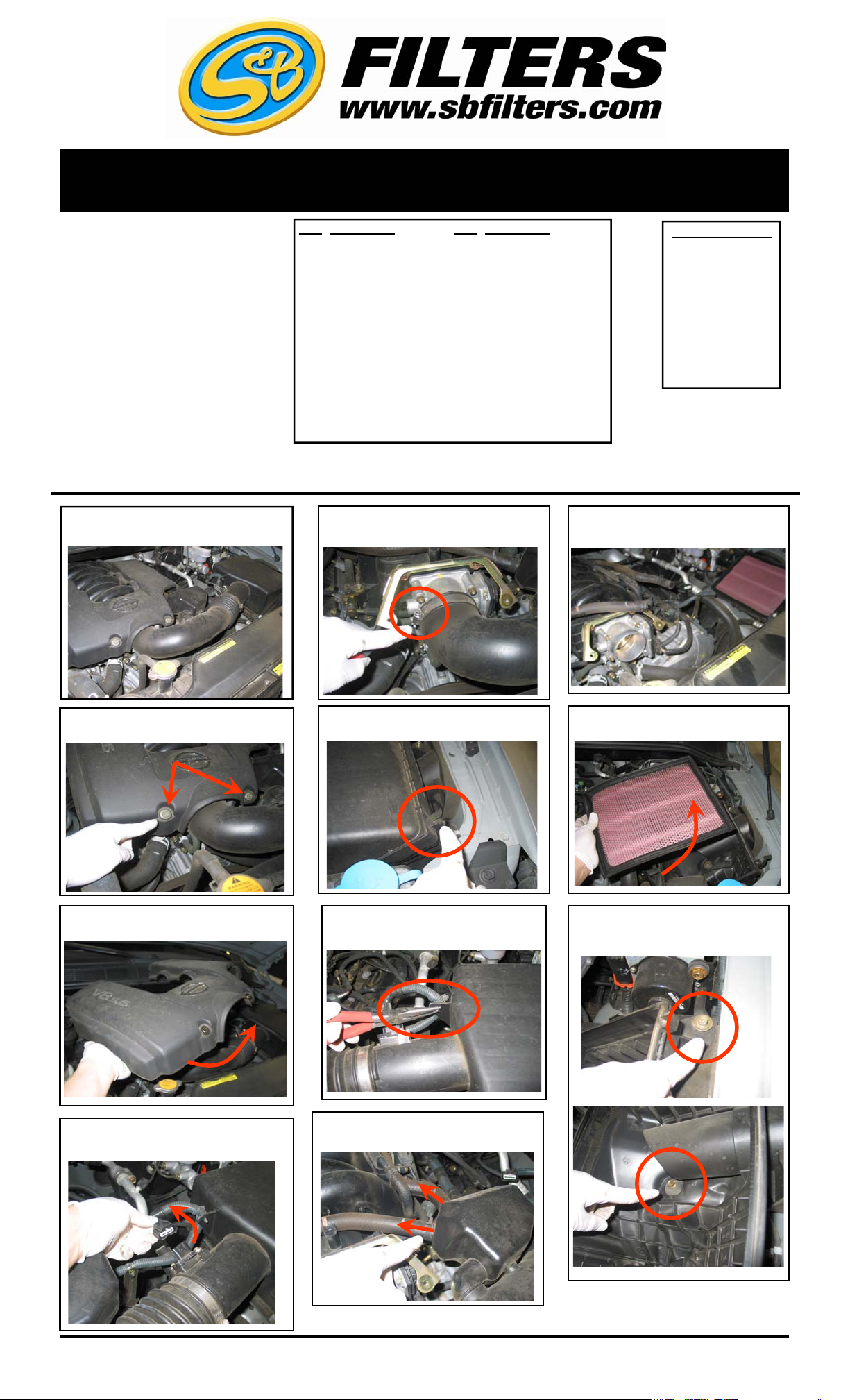
1. Turn off ignition and disconnect the
negative battery terminal.
Qx56 V8 5.6L
QTY PARTS LIST QTY PARTS LIST
1 3.25” x 2” Adapter 2 10-32 Pan Head Screw
1 Intake Tube 1 MAF Sensor Gasket
1 Air Box 2 1/2” x 4” long Hose
1 Clear Lid 2 5/8” to 1/2” Hose Barb
1 Air Filter 1 5/8” Washer
2 #52 Hose Clamp 1 M8 Hex Head Bolt
2 #8 MAF Screw 4 Sealing Washer
2 #8 Rubber Washer 4 SS Pan Head Screw
1 MAF Sensor Plate
5. Loosen the hose clamp at the
throttle body.
9. Remove the OE intake tube and
the top of the air box.
TOOLS REQUIRED
10mm Socket
12mm Socket
13mm Socket
Phillips Screwdriver
Flat Head Screwdriver
Pliers
2. Remove the bolts that secure the
engine dust cover.
3. Remove the dust cover.
6. Unclasp the clips that secure the
top of the air box.
7. Remove the MAF wiring harness
from the OE air box lid.
10. Remove the OE air filter from
the vehicle.
11. Remove the two bolts that secure
the OE lower air box to the inner
fender then remove the box.
4. Disconnect the electrical connection
for the MAF sensor.
6/9/2008
REV-A
(909) 947-0015 PHONE • (909) 947-0603 FAX
8. Disconnect the 2 CCV lines
from the OE intake tu
www.sbfilters.com
(OVER) S
Page 2
INSTALLATION INSTRUCTIONS (continued)
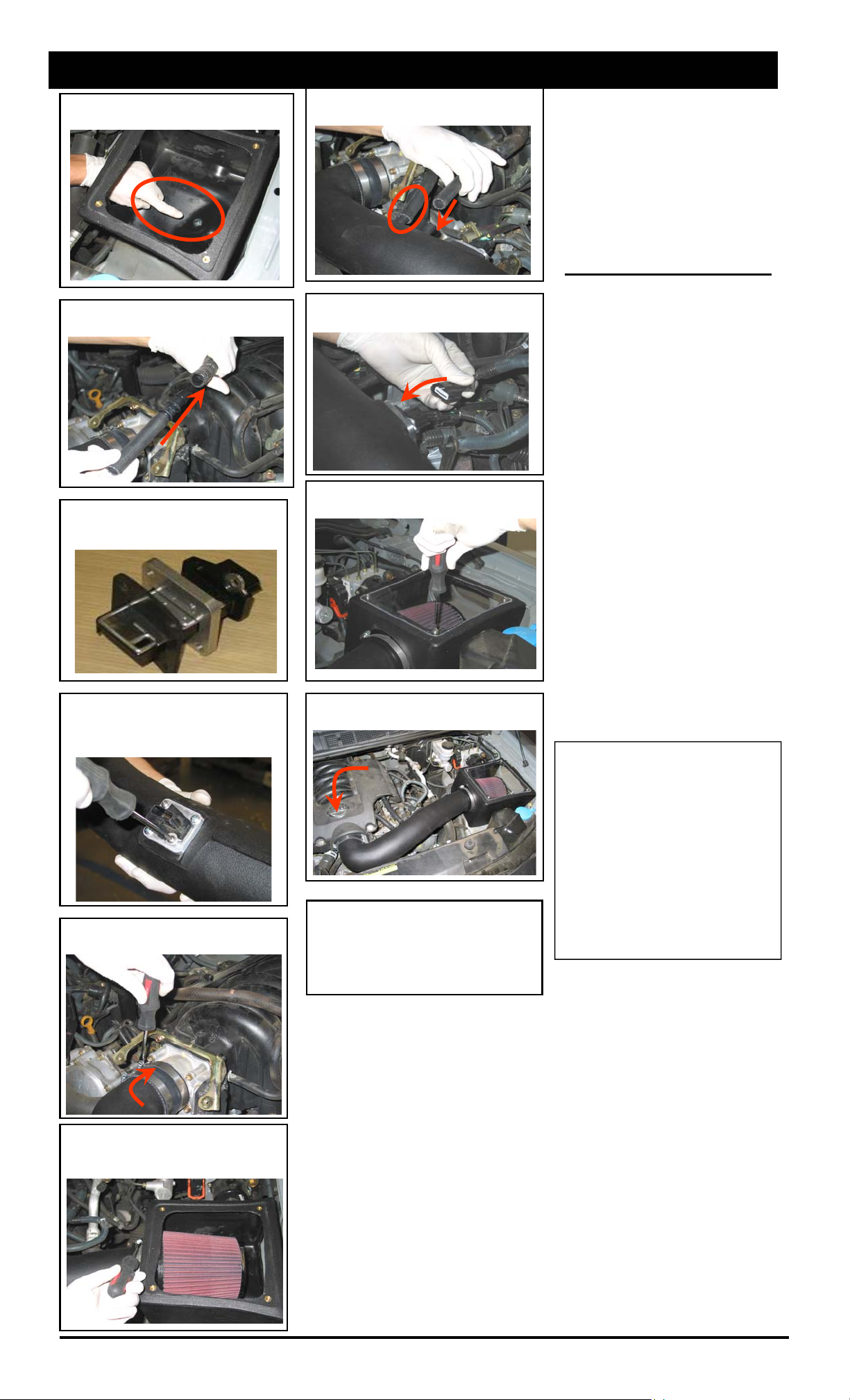
13. Install the S&B air box with the
8mm bolts and washers.
14. Install the 1/2” hoses and hose
barbs to the OE CCV lines.
15. Install the plate and gasket onto the
MAF sensor. Fasten the sensor onto
the plate using the supplied screws.
16. Install the MAF sensor assembly
onto the intake tube. Fasten the plate to
the tube using the supplied screws.
CHECK THE FLOW DIRECTION
17. Install the intake tube and loosely
secure the hose clamps.
19. Connect both CCV lines to the
intake tube.
20. Reconnect the MAF sensor electrical connection.
21. Remove the protective film from the
clear lid then attach it to the air box.
22. Install the engine dust cover and reconnect the negative battery terminal.
23. Check your installation and make
sure the kit is properly positioned and all
fasteners are secure. Apply the C.A.R.B.
sticker in plain site under the hood.
Your installation is now complete.
PERFORMANCE TESTING
∗
Engage parking brake and start
your engine. To ensure that the
system was installed properly,
listen for abnormal noises. If an
air leak is detected, re-inspect
hoses and connections as they
may need to be tightened.
∗ S&B FILTERS RECOMMENDS
THAT YOU KEEP YOUR OEM
INTAKE SYSTEM IN THE
EVENT IT IS REQURIED IN THE
FUTURE.
∗ In order to maintain proper war-
ranty, all connections and components must be checked periodically for realignment and to
tighten all connections. Failure to
do so will void your warranty.
∗ Use only S&B cleaning and oil
products to service your filter.
Using another company’s oil and
cleaner products may void your
warranty.
Smog Certification Note:
The California Air Resource Board
(CARB) requires that an E.O. identification label be applied to the vehicle in
order to pass a smog check inspection
when installing a High Performance
Intake Kit.
You must place the E.O. label provided on or near the intake kit after
installation so that the smog technician
can easily verify the O.E. number during the smog certification process.
18. Install the S&B air filter into the air
box and secure the hose clamp, secure
the hose clamps at the throttle body.
5/23/2011
REV-B
(909) 947-0015 Phone • (909) 947-0603 Fax
www.sbfilters.com
 Loading...