

Page 1
INSTALLATION INSTRUCTIONS
P/N: 75-5073 / 75-5073D
VEHICLE APPLICATION
Year: 2007-10
Make: DODGE
Model: RAM 3500-5500
Chassis Cab Only
Engine: 6.7L Cummins
2010 models: Classic body Only
NOTES
Kit may not fit with the following
Aftermarket Parts installed:
Remote Start
•
Body Lift or Lowering Kit
•
Custom Hood
•
Intercooler or Turbo upgrades
•
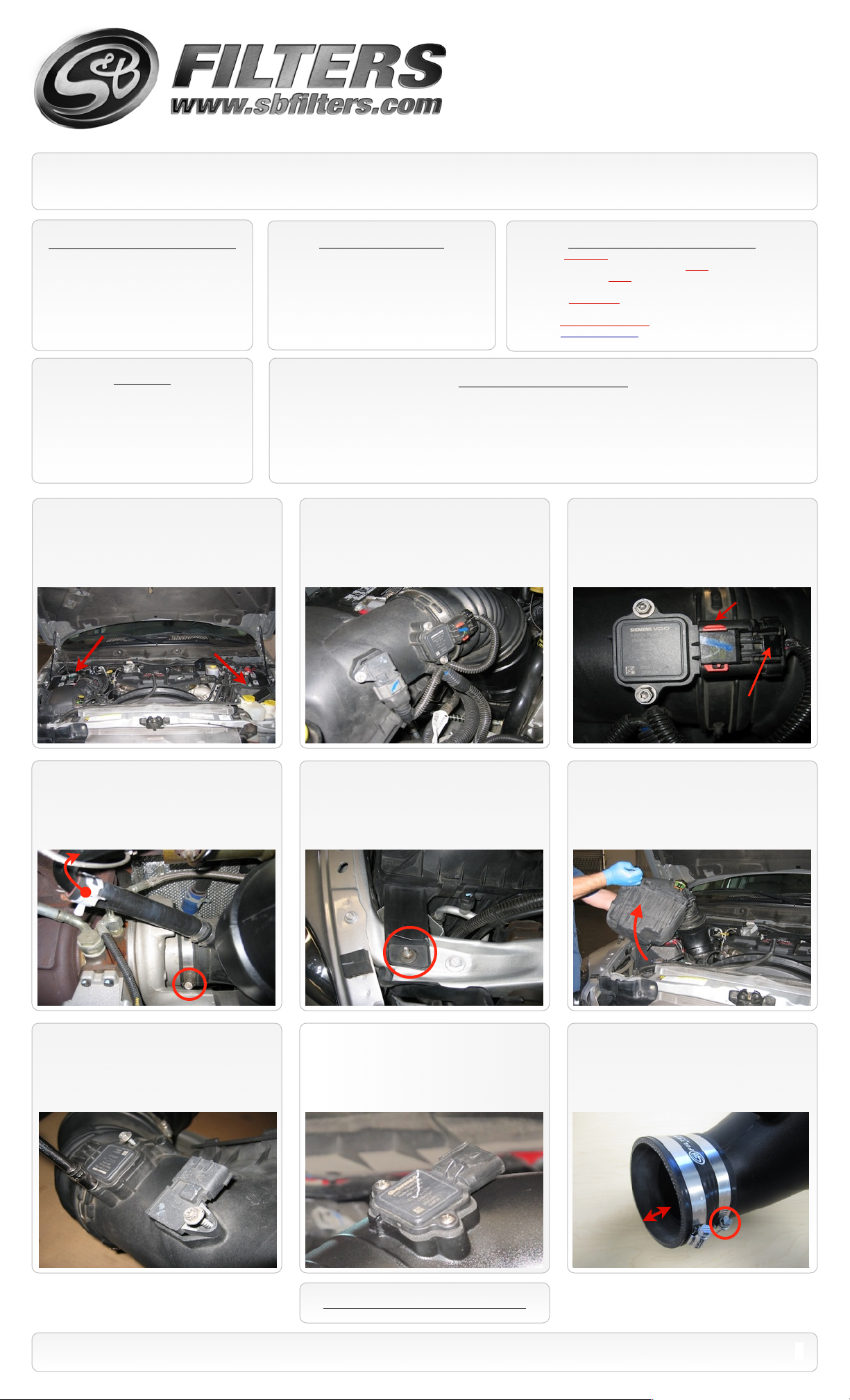
1. With the ignition switched off and the
parking brake set, disconnect the negative
battery cables on both batteries. (Failure to
disconnect the batteries may result in a
Check Engine Light)
TOOLS REQUIRED
8mm &10mm Wrench & Socket
•
T-20 Security Torx Wrench (Supplied w/ Kit)
•
7/16” Wrench and Socket
•
5/16” Nut Driver or Flat Blade Screwdriver
•
Phillips Screwdriver, Pliers or Channel locks
•
Cleanable (KF-1035). If the enclosed filter is Red, it came pre-oiled
from the factory. When serviced, apply (87g) of S&B oil to the main
body of the filter and (17g) to the Power Stack (Top).
Disposable (KF-1035D). If the enclosed filter is White, it is a
disposable filter and should be discarded once it reaches capacity.
This filter (does not require oil). For more info on S&Bʼs disposable
filter, visit www.sbfilters.com.
S&B FILTER MAINTENANCE
BEFORE YOU START
Please read the entire product guide before proceeding.
•
Ensure all components listed on page 4 are present.
•
If you are missing any of the components, call our customer support at (909) 947-0015.
•
Do not work on your vehicle while engine is hot.
•
Make sure the engine is turned off and the vehicle is in Park or the Parking Brake is set.
•
2. Disconnect the electrical connection for
the Intake Air Temp. (IAT) Sensor and the
Mass Air Flow (MAF) Sensor then unsnap the
wire loom from the tube. (See the next step
for removal)
3. For the MAF sensor, Slide the red locking
tab up then depress the black lever while
disengaging the connector. For the IAT
sensor just depress the grey lever while
disengaging the connector.
Locking Tab
4. Loosen the hose clamp at the turbo inlet,
next pinch the spring clamp and slide it up the
steel piping. Then disconnect the silicone
hose from the steel piping and remove spring
clamp.
7. Carefully remove both sensors from the
stock air box and set them aside for now.
5. Remove the mounting nut on the stock air
box.
8. Use the supplied 8-32 SS Screws (F)
and Sensor Gasket (E), and install the MAF
sensor into Intake Tube (C). Do not over
tighten.
Lever
6. Lift up and out to remove the stock air
box assembly from the vehicle.
9. Place the Silicone adapter (B) and both
#64 Hose Clamps (A) onto the Intake tube (C)
as shown. Leave 1.25” between the end of
the silicone and the end of the intake tube.
Tighten the clamp on the intake tube.
1.25”
SEE EXPLODED VIEW ON PAGE 4
15461 Slover Ave., Fontana, CA 92337 - Phone: (909) 947-0015 - Fax: (909) 947-0603 - www.sbfilters.com
1
Page 2
INSTALLATION INSTRUCTIONS (continued)
P/N: 75-5073 / 75-5073D
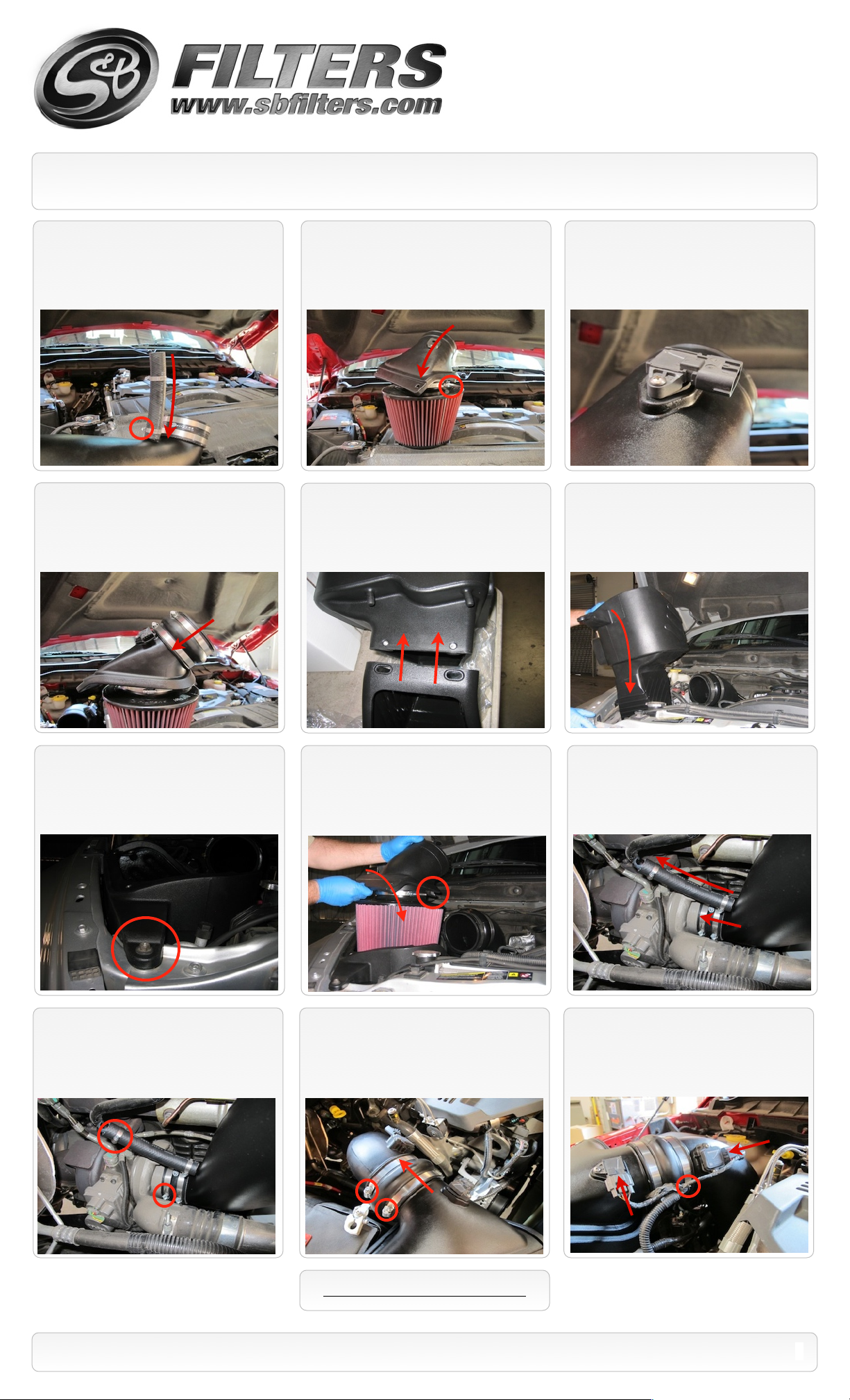
10. Slide the Breather hose over the spout
on the Intake tube (C). Slide both #12 Hose
clamps (X) over the hose and tighten the
clamp on the spout.
14. Slide the 2 #72 Hose clamps (H) over
the Hump Adapter (G). Then push the Hump
adapter (G) over the Adapter tube (K). Leave
clamps loose for now.
11. Place the Adapter tube (K) into the
base of the S&B Air Filter (J) and tighten the
#88 Hose clamp.
15. Attach the Splash Guard (V) to the Air
Box (Q), use the supplied hardware to
secure as instructed in the exploded
view.
12. Use the remaining 8-32 SS Screw
(F) and IAT Sensor Gasket (D), and install the
IAT sensor into Adapter Tube (K).
16. Apply a light amount of grease to the
two prongs on the bottom of the box (Q)
before installing the Air Box assembly into the
vehicle.
17. Attach the Air Box (Q) using the stock
nut removed in Step #5. Leave loose at this
time, it will be tightened in step #24.
20. Make sure the Intake tube (C) and
Adapter tube (K) are aligned up top and
tighten the hose clamp at the turbo
connection. Also tighten the hose clamp at
the crankcase breather connection.
18. Carefully place the filter assembly into
the Air Box trying not to ding or gouge the
wire mesh. Rotate the Filter Adapter
assembly into position and hook the clip into
the Air Box.
21. Slide the Hump Adapter (G) over the
Intake tube (C) and secure both the #72 Hose
Clamps (H).
19. Install the Intake tube assembly by
sliding the breather hose over the steel tube
on the truck. Then push the silicone adapter
over the turbo inlet. Leave loose for now.
22. Reconnect the MAF sensor and IAT
sensor wiring harnesses to the sensors. It
may be necessary to remove the wire tie to
get more slack in the wires.
SEE EXPLODED VIEW ON PAGE 4
15461 Slover Ave., Fontana, CA 92337 - Phone: (909) 947-0015 - Fax: (909) 947-0603 - www.sbfilters.com
2
Page 3

EMISSIONS STANDARD
The California Air Resource Board (CARB) requires that an E.O. identification label be applied to the vehicle in order to pass a smog
check inspection when a Performance Intake Kit has been installed. You must place the E.O. label provided on or near the intake kit
after installation so that a smog check technician can easily verify the E.O. number. As of April 2009, S&B has never had a product
where CARB denied an exemption request; however, the exemption process with CARB can take as long as 18 months. Check the
status of the exemption process by looking up a specific part number at www.sbfilters.com. The CARB Exemption number and/or
status is listed under the Product Details section for each part number. If the status shows as “Pending,” CARB has yet to issue an
exemption. Products that have not been issued an EO number are street legal in most states, but may not be used on emission
controlled vehicles in the state of California and are for off road use only. If you purchased your kit from S&B Filters directly, we will
automatically mail you your Exemption Sticker when it is issued to us. If you purchased your kit from an authorized S&B Filters Dealer,
log onto our web site and register to receive your Exemption Sticker.
INSTALLATION INSTRUCTIONS (continued)
P/N: 75-5073 / 75-5073D
23. Install the Clear Lid (P) using the
supplied 5/16” S.S. Screws (M) and Rubber
Washers (L) along with the 10-24 Screws (N)
and SS Sealing Washers (O). This will secure
the Filter Adapter to the Air Box as well.
PRECISION II
FILTER CLEANING & OILING
24. Reconnect both batteries. Inspect your
installation, make sure the kit is properly
positioned and all fasteners are secure. Affix
the CARB sticker near the intake kit. The
installation is now complete.
RELATED ITEMS FOR YOUR
PURCHASE
Replacement Air Filter (Oiled)
•
(S&B P/N: KF-1035)
Replacement Air Filter (Dry)
•
(S&B P/N: KF-1035D)
Air Filter Wrap (S&B P/N: WF-1023
•
PERFORMANCE TESTING
Engage parking brake and start your engine.
•
Listen for abnormal noises. If an air leak is
detected, re-inspect hoses and connections as
they may need to be repositioned and
tightened.
S&B FILTERS recommends that you keep
•
your OE intake system in the event it is
required in the future.
In order to maintain your warranty, all
•
connections and components must be
checked periodically for alignment and for
proper tension on all connections. Failure to
do so may void your warranty.
Order online today at www.sbfilters.com or
through your local S&B distributor.
Part #: 88-0008
SEE EXPLODED VIEW ON PAGE 4
Use only S&B FILTERS cleaning and oil
•
products to service your filter. Using any other
brand oil and or cleaners on your S&B air filter
may void your warranty.
15461 Slover Ave., Fontana, CA 92337 - Phone: (909) 947-0015 - Fax: (909) 947-0603 - www.sbfilters.com
3
Page 4

ITEM
QTY.
DESCRIPTION
P/NA2
Hose Clamp, #64
AI1018-00
B1Silicone Adapter, 4.10” x 2.0”
AI1029S-00
C1Intake Tube
AL1162-00
D1IAT Sensor Gasket
AI1302-00
E1MAF Sensor Gasket
AI1301-00
F3S.S. Screw, 8-32 x 1/2”
AI1479-00
G1Hump Adapter, 4.50” x 3.0”
AI1462C-00
H2Hose Clamp, #72
AG1009-00
I1Hose Clamp, #88
AG1011-00
J1S&B Air Filter
KF-1035K1
Filter Adapter Tube
AL1161-00
L2Rubber Washer
AI1435-00
M2S.S. Screw, 5/16-18 x 1.0”
AI1297-00
N2S.S. Screw, 10-24 x 1/2”
AI1287-00
ITEM
QTY.
DESCRIPTION
P/NO2
S.S. Sealing Washer, 10-24
AI1272-00
P1Clear Box Lid
AI1442-00
Q1S&B Air Box
AL1107-00
R4Washer/ Spacer, 8mm
AI1402-00
S2Washer, Flat, 1/4”
AI1073-00
T2Washer, Lock, 1/4”
AI1309-00
U2Hex Bolt, 1/4-20 x 3/4”
AI1068-00
V1Splash Guard
AL1109-00
W1Breather Hose, 3/4”x7.0”
AI1040-00
X2Hose Clamp, #12
AG1030-00
EXPLODED VIEW
AM0183-00 Rev.A 04/25/12
P/N: 75-5073 / 75-5073D
15461 Slover Ave., Fontana, CA 92337 - Phone: (909) 947-0015 - Fax: (909) 947-0603 - www.sbfilters.com
4
 Loading...