

Page 1
Installation Instructions
P/N: 75-5068 / 75-5068D
Approx. Install Time 3Hrs 00Min
Vehicle Application
Year: 2013 - 2014
Make: Ram
Model: 2500/3500 Diesel
Engine: 6.7L Cummins
Notes
Kit may not fit with the following
Aftermarket Parts installed:
Body Lift or Lowering Kit
•
Custom Hood
•
Intercooler or Turbo upgrades
•
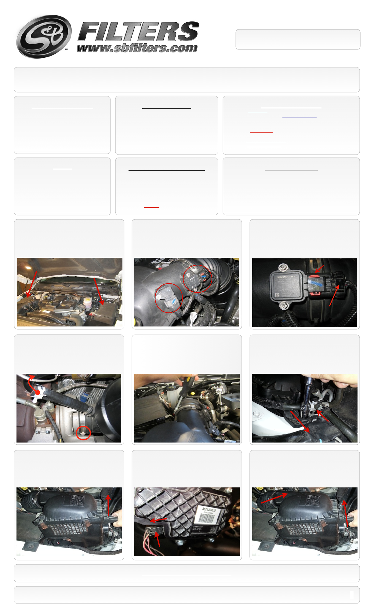
1. With the ignition switched off and the
parking brake set, disconnect the negative
battery cables on both batteries.
Tools Required
7mm, 8mm, 10mm,& 13mm Wrench & Socket
•
1/8” Allen Key (Supplied w/ Kit), 3/16” Allen Key
•
T27 Security Torx Wrench
•
5/16” Nut Driver or Flat Blade Screwdriver
•
Phillips Screwdriver, Pliers or Channel locks
•
5/16” Drill bit and Drill
•
Electrical Tape
•
Razorblade
•
CARB Status - Pending
Product will be submitted to Air Resources
Board for approval shortly.
Not legal for use in CA or other states
adopting CA emissions standards See
Page 6 for more info.
2. Disconnect the electrical connection for the
Intake Air Temp. (IAT) Sensor and the Mass Air
Flow (MAF) Sensor then unsnap the wire loom
from the tube. (See the next step for removal)
Cleanable (KF-1037). If the enclosed filter is Red, it came pre-oiled
from the factory. Please visit www.sbfilters.com for exact oil
amount required after cleaning.
Disposable (KF-1037D). If the enclosed filter is White, it is a
disposable filter and should be discarded once it reaches capacity.
This filter (does not require oil). For more info on S&Bʼs disposable
filter, visit www.sbfilters.com.
Before You Start
S&B Filter Maintnance
Please read the entire product guide before proceeding.
•
Ensure all components listed on page 4 are present.
•
If you are missing any of the components, call customer support
•
at (909) 947-0015.
Do not work on your vehicle while engine is hot.
•
Make sure the engine is turned off and the vehicle is in Park or
•
the Parking Brake is set.
3. For the MAF sensor, slide the red locking
tab up then depress the black lever while
disengaging the connector. For the IAT
sensor just depress the grey lever while
disengaging the connector.
Locking Tab
4. Loosen the hose clamp at the turbo inlet,
next pinch the spring clamp and slide it up the
steel piping. Then disconnect the silicone
hose from the steel piping and remove spring
clamp.
7. Lift up on factory air box, be careful not to
remove the whole box because the swing gate
motor harness is still connected on the side of the air
box. Remember to move the hose forward from Step
6 when pulling out the box.
5. Loosen the hose clamp on the intake
tube to assist with the removal of the air box.
8. Disconnect the factory swing gate motor
connector that is located on the side of the
factory air box. Press in the locking button on
the connector and pull out.
Lever
6. Remove factory retaining bolt on the front of
the factory air box. Once retaining bolt is
removed disconnect hose clip by pulling up and
then move hose forward to help remove air box.
(See Below)
9. Once the swing gate motor is
disconnected completely remove the factory
air box and intake tube by lifting up and out.
SEE EXPLODED VIEW ON PAGE 7
15461 Slover Ave., Fontana, CA 92337 - Phone: (909) 947-0015 - Fax: (909) 947-0603 - www.sbfilters.com
1
Page 2
Installation Instructions (continued)
P/N: 75-5068 / 75-5068D
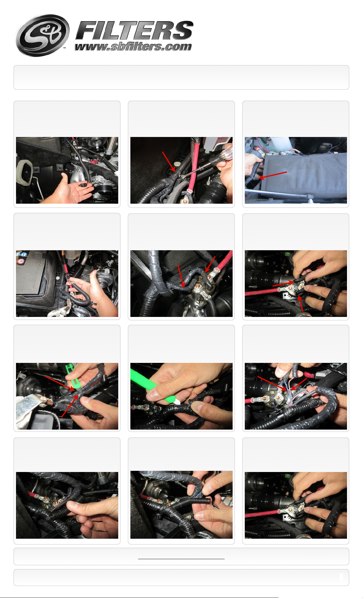
10. Once the factory air box and intake tube
are removed the swing gate motor harness
must be modified for the harness to reach the
S&B air box.
13. Once the push pins are pulled out the
harness can be pulled out further.
11. First remove the harness push pins that
hold the harness down to the battery tray
using a pry tool or flat head screw driver.
14. Pull the harness until it is stopped by
these wires hooked up to the relay
component.
12. Remove the push pins on the harness
that are located on the side and back of the
battery tray.
15. Disconnect the wires from the relay component by
pulling them off. Please take note on which wire was
connected to which terminal because these wires will be
reconnected after modification. Please mark each wire
or take a photo to help remember the wire connections.
16. Cut into the base of the insulation on
each line being careful not the cut or damage
the wires inside.
19. Use the provided insulated sleeve (AC)
to insulate both wires together. The insulated
sleeve gives the wires added protection.
17. Once the insulation is cut at the base of
each line carefully cut into the main harness
and again be careful not to cut or damage the
wires inside.
20. Install the insulated sleeve (AC) over both
wires, this extra length will let the harness extend
and reach the S&B air box. Re-apply electrical tape
to any exposed wires and sleeve to avoid corrosion.
18. Once the insulation is cut pull a length
of about 3 inches for each line.
21. Once both lines are insulated with the
provided insulation sleeve reconnect each
wire to the correct terminal on the relay
component.
SEE EXPLODED VIEW ON PAGE 7
15461 Slover Ave., Fontana, CA 92337 - Phone: (909) 947-0015 - Fax: (909) 947-0603 - www.sbfilters.com
2
Page 3
Installation Instructions (continued) (Optional Step)
P/N: 75-5068 / 75-5068D
LIGHT WIRE
Swing Gate Motor Harness
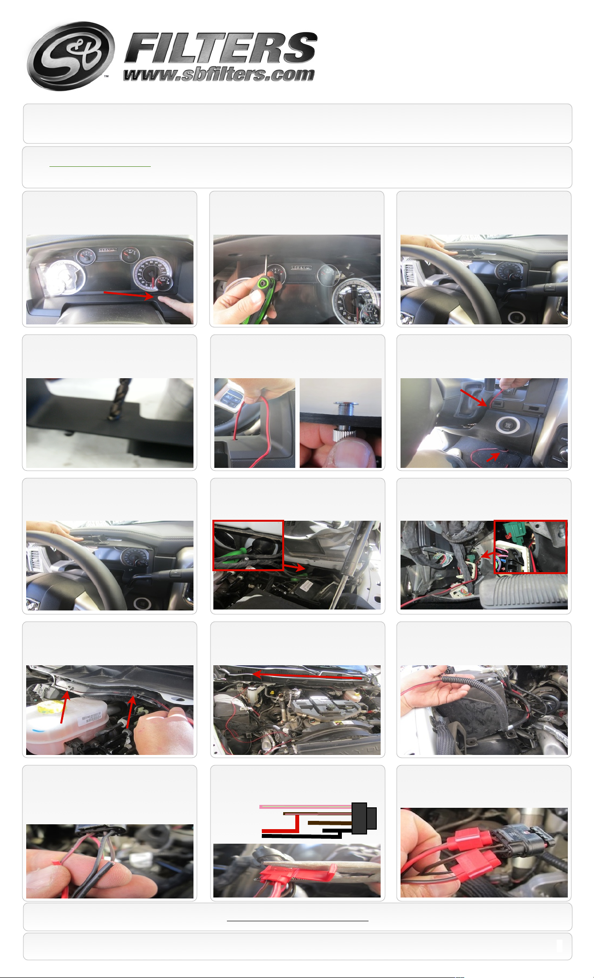
22. Active Monitoring Light Install Light may be installed if desired, we recommend on the trim of the instrumentation panel inside the cab (Warning:
drilling of the instrument panel will be required)
A. Choose a location to drill a hole to install
the monitoring light.
D. Carefully drill a hole using a 5/16” drill bit, use
lower rpm speeds and start hole with smaller bits
like a 1/8” or 3/16” to avoid damage to panel.
B. Remove panel by first removing the 4 Torx
screws under top part of instrument panel.
E. Install monitoring light (AD) into the drilled out
hole, screw the locking nut onto the back of the
panel by running the wire through the nut.
C. Once Torx are removed pull down and out
to remove panel. (lowering of shifter and
steering wheel may be required).
F. Before re-installing the panel run the
indicator light wire down through the steering
column to the bottom of the dash.
G. Reinstall panel, again steering column and
gear shifter may need to be lowered to install
panel.
J. Pull wire through fire wall and run wire
through the vehicles wire/cable guard. A
screwdriver may be needed to unlock tabs.
H. From under the hood on the driver side firewall,
carefully insert a screw driver on the side of the
rubber boot to help run the indicator wire through.
K. Below is a photo of the wire being ran
through the wire/cable guard. Remember to
lock tabs when finished running wire through.
I. From under the dash run the wire through fire wall
to the outside were the screw driver enters the
firewall, use zip ties to fasten down the indicator wire
as needed.
L. Once done running the wire through the guard,
run wire down along the side of the battery. It is
recommended to run the wire through the swing
gate motor harness.
M. This is a photo of how the indicator wire
will be connected into the swing gate motor
harness wires. The Red will connect to the
Brown w/Pink and the Black will connect to
the Black wire. (See illustration on next step)
15461 Slover Ave., Fontana, CA 92337 - Phone: (909) 947-0015 - Fax: (909) 947-0603 - www.sbfilters.com
N. Use the provided tap connectors (AE) to tap both
wires together using pliers. Tap the RED wire into the
Brown w/Pink wire and tap the Black into the Black wire
on the harness.
INDICATOR
SEE EXPLODED VIEW ON PAGE 7
M. Photo of finished harness with the correct wire
taps. It is recommended to use zip ties on lose wires
and to also use electrical tape over the tap
connectors for added protection.
3
Page 4

Installation Instructions (continued)
P/N: 75-5068 / 75-5068D
23. Remove the MAF sensor and IAT
Sensor from the factory air box by removing
the three factory bolts.
26. A good amount of force may be required to
remove the motor from the factory air box. The motor
shaft may need to be rotated while removing from the
factory butterfly valve in the factory air box. Grab both
the butterfly valve and motor and twist while pulling out.
24. Place MAF sensor and IAT Sensor onto
the S&B intake tube (X) using the 8-32 pan
head screws (U) and gaskets (V&W).
27. Mount the swing gate motor onto the
bottom of the S&B intake air box (I) using
spacers (K) and screws (M) and washers
(BB).
25. Remove the swing gate motor (L) from
the side of the factory air box using a T-27
torx key.
28. Construct the S&B Swing Gate Dam to Arm (N&S)
using the provided hardware (O,P,&R) and using the provided
Allen key (AB). If you desire to have both inlets open in the
air box skip this step. Warning: The Dam (N) must be
installed during harsh weather including but not limited to
rain, ice, sleet or snow; or engine damage could result.
29. When placing the swing gate arm (S) onto
motor (L) please make sure the flat side of the swing
gate arm is placed correctly on the flat side of the
motor shaft. Push down on diverter base all the way
down till it snaps into place.
31. Install the provided inlets (G&J) and tube seal
(Q) into the S&B air box (I) by inserting and
snapping into place. A bit of force and effort may be
necessary to install inlets and seal. Line up each
part with the dot on the box.
30. Note: Do NOT remove Swing Gate Arm (S)
after installing it to the motor as this could
damage the snap in feature of the arm. If
removal of Dam (N) is desired, remove with Arm
(S) installed on motor (L).
32. Install the hose (T) with (Y) hose clamps. Next
install coupler (Z) and hose clamps (AA) onto the
S&B intake tube (X). Remember to only tighten hose
clamps (Y) and (AA) on the tube side.
Warning: Never operate the vehicle with
the Swing Gate Arm (S) removed or a
Active Air Box Error will result & require
the motor to be sent to S&B to be reset.
The Dam (N) can be removed during
good weather conditions. See #28
above.
33. Install S&B intake tube (X) into S&B air
box (I) by sliding the tube through the tube
seal (Q). This should be a snug fit. A perfect
seal is not required.
SEE EXPLODED VIEW ON PAGE 7
15461 Slover Ave., Fontana, CA 92337 - Phone: (909) 947-0015 - Fax: (909) 947-0603 - www.sbfilters.com
4
Page 5

Installation Instructions (continued)
P/N: 75-5068 / 75-5068D
34. Place the S&B air box with air tube
assembly into vehicle.
Read step 35 before continuing with #34
36.(b) Reach under the air box to feel if the
posts pushed through the holes (grommets).
Be careful not to push to hard or the tabs will
break off the battery tray.
35. Before installing the air box and tube
assembly attach the swing gate harness
connector to the swing gate motor (L) that is
located underneath the S&B air box.
37. After dropping in the box move hose
forward to let the box drop down completely.
Once box is dropped flush reconnect hose
clip to the vehicle.
36.(a) When fitting the S&B intake box into
the vehicle please make sure that the stand-off
post on the bottom of the air box fit properly into
the holes on the air box tray in the vehicle.
38. Push down on air box and tighten the
provided retaining bolt (H).
39. Connect hose (T) and tighten hose
clamp (Y).
42. Install the filter (E), please make sure to
install with flat side up and feed the filter onto
tube and push down. Once installed tighten
hose clamp.
40. Connect coupler (Z) to turbo and tighten
hose clamp (AA). Please make sure the
coupler is push all the way onto turbo before
tightening completely.
43. Install the provided edge trim (C) around
lid (D)
41. Reconnect the MAF and IAT sensor.
44. Once edge trim is installed roll the sides
of the lid on a flat surface to ensure a tight
seal.
SEE EXPLODED VIEW ON PAGE 7
15461 Slover Ave., Fontana, CA 92337 - Phone: (909) 947-0015 - Fax: (909) 947-0603 - www.sbfilters.com
5
Page 6

Installation Instructions (continued)
P/N: 75-5068 / 75-5068D
1/4” hardware (A&B).
Our active monitoring light
alerts you when the ram-air
gate is open.
46. Reconnect both batteries
Precision II
Filter Cleaning & Oiling
47. The Installation is now complete.45. Install the lid (C) using the provided
RELATED ITEMS FOR YOUR
PURCHASE
Replacement Air Filter (Oiled)
•
(S&B P/N: KF-1037)
Replacement Air Filter (Dry)
•
(S&B P/N: KF-1037D)
Air Filter Wrap (S&B P/N: WF-1037)
•
Order online today at www.sbfilters.com or
through your local S&B distributor.
Part #: 88-0008
Performance Testing
Engage parking brake and start your engine. Listen for abnormal noises. If an air leak is detected, re-inspect hoses and connections as they may need to be repositioned and
•
tightened.
S&B FILTERS recommends that you keep your OE intake system in the event it is required in the future.
•
In order to maintain your warranty, all connections and components must be checked periodically for alignment and for proper tension on all connections. Failure to do so
•
may void your warranty.
Use only S&B FILTERS cleaning and oil products to service your filter. Using any other brand oil and or cleaners on your S&B air filter may void your warranty.
•
Warning!
If your vehicle has a Vehicle Emission Control Information decal affixed to the factory airbox, a new
replacement label must be obtained and installed in a readily visible position in the engine compartment in
order to remain CARB compliant. Failure to do so will prevent the vehicle from passing a smog check.
Replacement labels can be ordered from your local dealership. Regulations state that the VECI label shall
not be affixed to any equipment which is easily detached from the vehicle. Label placement, under the hood
on a painted surface is recommended.
Emissions Standard
The California Air Resource Board (CARB) requires that an E.O. identification label be applied to the vehicle in order to pass a smog check inspection when a Performance
Intake Kit has been installed. You must place the E.O. label provided on or near the intake kit after installation so that a smog check technician can easily verify the E.O. number.
As of April 2009, S&B has never had a product where CARB denied an exemption request; however, the exemption process with CARB can take as long as 18 months. Check
the status of the exemption process by looking up a specific part number at www.sbfilters.com. The CARB Exemption number and/or status is listed under the Product Details
section for each part number. If the status shows as “Pending,” CARB has yet to issue an exemption but the product has been submitted. Products that have not been issued an
EO number are street legal in most states, but may not be used on emission controlled vehicles in the state of California and are for off road use only. If you purchased your kit
from S&B Filters directly, we will automatically mail you your Exemption Sticker when it is issued to us. If you purchased your kit from an authorized S&B Filters Dealer, log onto
our web site and register to receive your Exemption Sticker.
SEE EXPLODED VIEW ON PAGE 7
15461 Slover Ave., Fontana, CA 92337 - Phone: (909) 947-0015 - Fax: (909) 947-0603 - www.sbfilters.com
6
Page 7

ITEM
QTY.
DESCRIPTION
P/N
A4S.S. Screw #10-24 x1/2”
AI1539-00
B4Sealing Washer #10
AI1540-00
C1Edge Trim
AI1620-01
D1Lid
AI1613-00
E1S&B Air Filter
KF-1037F1
Filter Hose Clamp #72
AG1009-00
G1Side Inlet Seal
AI1610-00
H1S.S. Allen Head M8
AI1369-00
I1Air Box
AL1218B-00
J1Front Inlet Seal
AI1610-00
K4Spacer
AI1621-00
L1Factory Swing Gate Motor
------------------
M4Screw #10-24 x 1.75”
AI1619-00
N1Swing Gate Dam
AI1623-00
O4Flat Washer #10
AI1226-00
P2Screw S.S. #10-24 x 3/4”
AI1624-00
Q1Tube Seal
AI1614-00
ITEM
QTY.
DESCRIPTION
P/N
R2Locknut 10-24
AI1047-00
S1Swing Gate Arm
AI1622-00
T1Hose 3/4” x 7”
AI1040-05
U3S.S. Pan Head Screw 8-32 x 1/2”
AI1479-00
V1Gasket MAF
AI1301-00
W1Temp Gasket
AI1302-00
X1Intake Tube
AL1218-00
Y2Hose Clamp #12
AG1030-00
Z1Silicone Adapter, 4.10”IDx2.00”
AI1029C-00
AA2Hose Clamp #64
AG1018-00
BB4Sealing Washer #10 S.S
AI1273-00
PARTS BELOW ARE NOT IN VIEW
AB1Hex Allen Key 1/8”
AI1634-00
AC1Insulation Sleeve 6.0”
AI1625-01
AD1Monitor Light 4M Red/Blk Wire
AI1627-00
AE23M Quick Splice
AI1628-00
AF5Zip Ties
AI1212-00
Exploded View
AM0174-00 Rev.C 12/23/13
P/N: 75-5068 / 75-5068D
Warranty
Visit www.sbfilters.com for complete warranty information.
15461 Slover Ave., Fontana, CA 92337 - Phone: (909) 947-0015 - Fax: (909) 947-0603 - www.sbfilters.com
7
 Loading...