

Page 1
Installation Instructions
P/N: 75-5064 / 75-5064D
Vehicle Application
Year: 2009-13
Make: DODGE/ RAM
Model: 1500
Engine: 5.7L Hemi
Note: Will Not fit 2500 models
Notes
Kit may not fit with the following
Aftermarket Parts installed:
Body Lift or Lowering Kit
•
Custom Hood
•
Throttle body upgrades
•
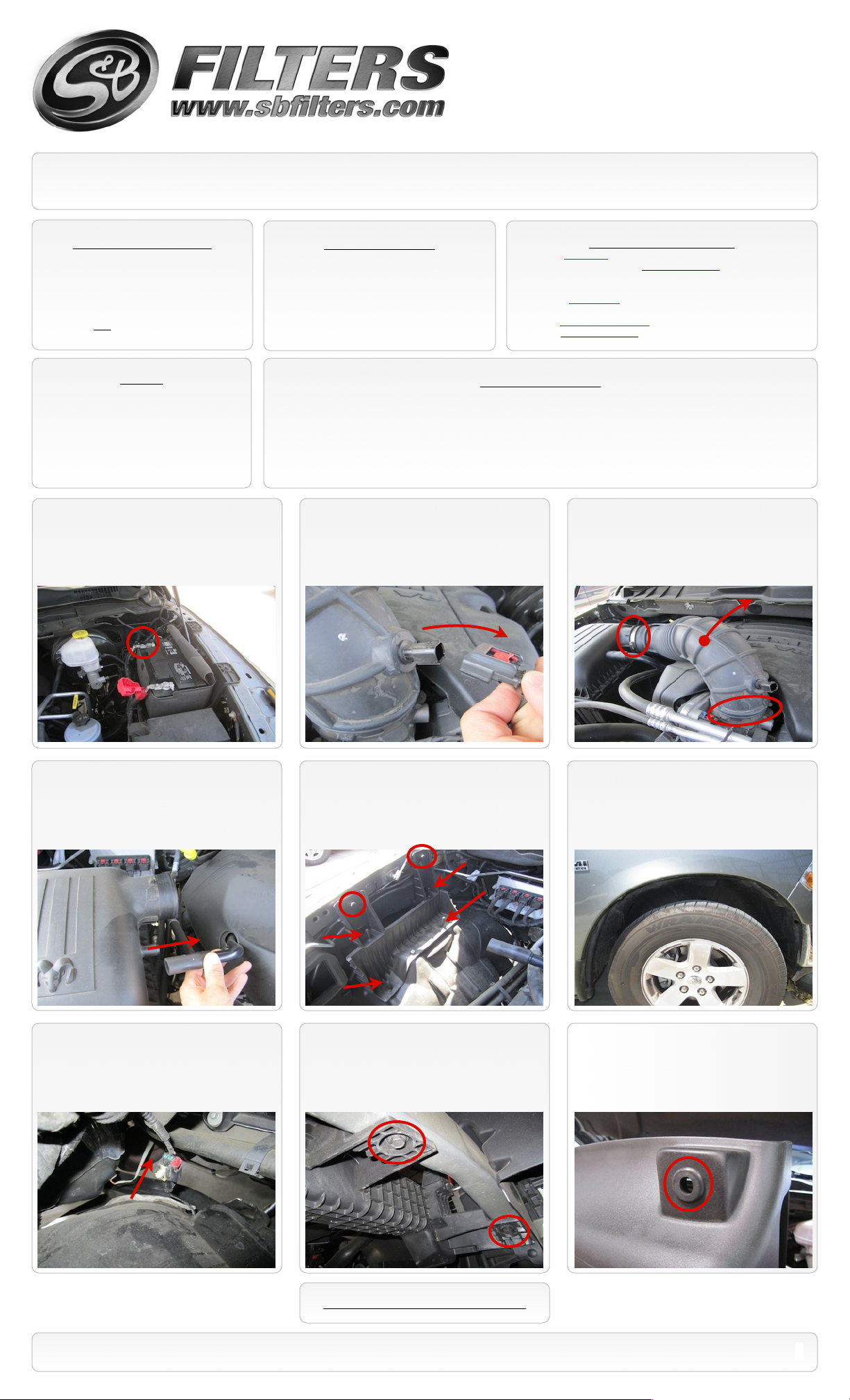
1. With the ignition switched off and the
parking brake set, disconnect the negative
battery cable on the driver’s side.
Tools Required
8mm, 10mm, 13mm Wrench & Socket
•
Pin Removal Tool or Flat Blade Screwdriver
•
7/16” Wrench and Socket
•
5/16” Nut Driver or Flat Blade Screwdriver
•
Phillips Screwdriver
•
Cleanable (KF-1056). If the enclosed filter is Red, it came pre-oiled
from the factory. Please visit www.sbfilters.com for the exact oil
amount required after cleaning.
Disposable (KF-1056D). If the enclosed filter is White, it is a
disposable filter and should be discarded once it reaches capacity.
This filter (does not require oil). For more info on S&Bʼs disposable
filter, visit www.sbfilters.com.
S&B Filter Maintanence
Before You Start
Please read the entire product guide before proceeding.
•
Ensure all components listed on page 4 are present.
•
If you are missing any of the components, call our customer support at (909) 947-0015.
•
Do not work on your vehicle while engine is hot.
•
Make sure the engine is turned off and the vehicle is in Park or the Parking Brake is set.
•
2. Disconnect the electrical connection for
the Temp (IAT) Sensor. Note the sensorʼs
orientation for the re-install.
3. Loosen the hose clamp connecting the
tube to the air box and the clamp attaching
the tube to the throttle body. Then remove
intake tube from the truck.
4. Remove the crank case vent tube from
the air box.
7. From inside the engine compartment,
carefully pull the wiring harness connector out
from the wheel liner. Then remove the wheel
liner from the truck.
5. Remove air box by carefully pulling the air
box up out of the four pins in the air box tray.
Then remove the two bolts mounting the tray
to the frame using 13mm socket.
8. Using 13mm socket, remove the other 2
bolts securing the air box tray. Then remove
the tray from the truck
6. Remove the seven screws securing the
wheel liner using 8mm socket. Then remove
the 3 push pins. S&B has supplied new panel
pins in the event that the OE pins are
damaged during removal.
9. Insert the supplied Grommet (D) into the
Air Box (M).
SEE EXPLODED VIEW ON PAGE 4
15461 Slover Ave., Fontana, CA 92337 - Phone: (909) 947-0015 - Fax: (909) 947-0603 - www.sbfilters.com
1
Page 2
Installation Instructions (continued)
P/N: 75-5064 / 75-5064D
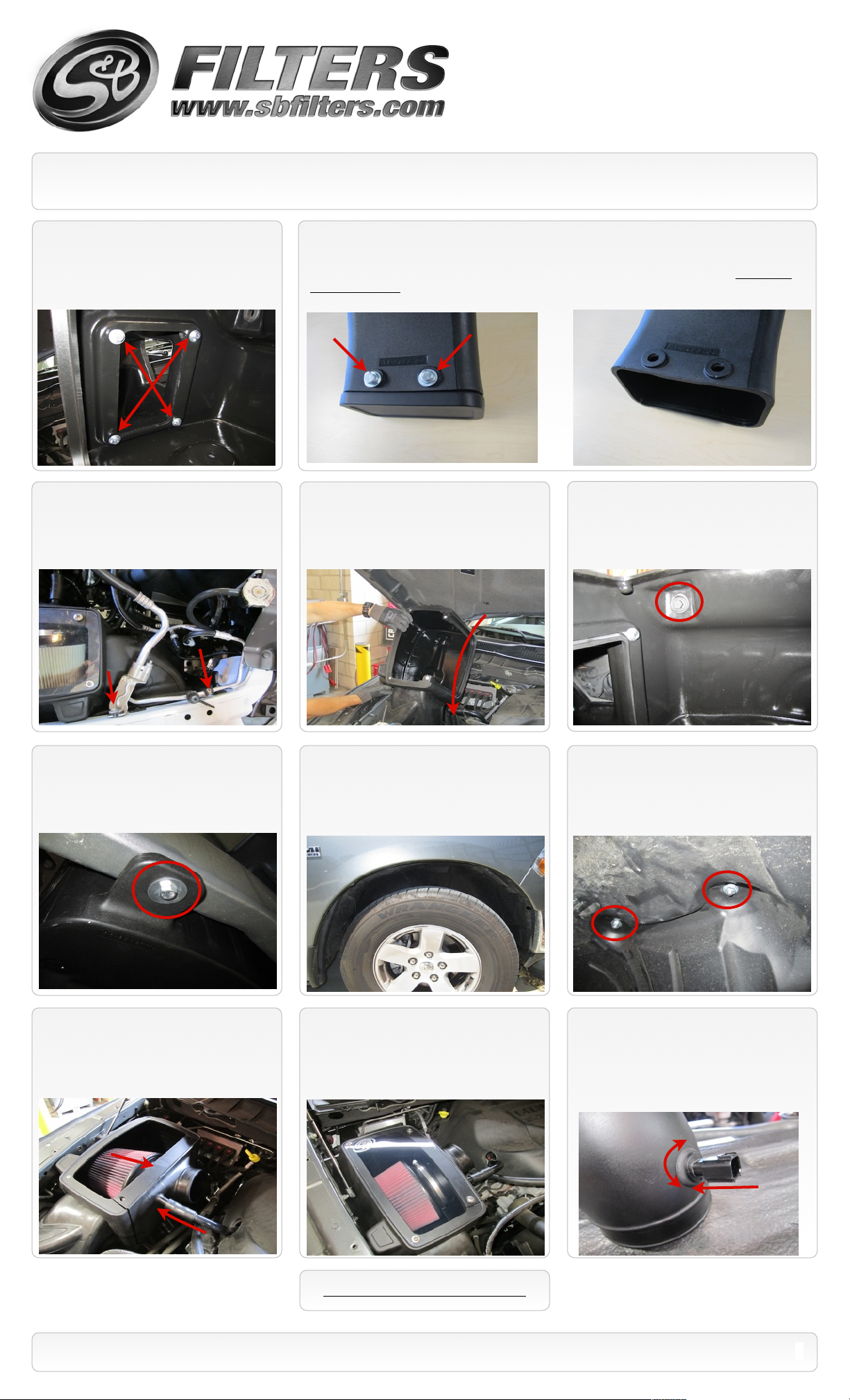
10. Insert the Air Inlet tube (S) onto the Air
Box (M) and secure using the supplied
1/4”-20x3/4” screws (V), 1/4” Lock washers
(U) and 1/4” Flat washers (W).
12. On 2013 models; it may be necessary
to shift the A/C line assembly forward to gain
clearance around the Inlet tube. This can be
done loosening the two screws attaching the
assembly to the fender.
11. For those concerned about minimal engine heat; insert the Air Inlet Plug (T) into the end of the
Air Inlet tube (S). Attach using the supplied 1/4”-20x3/4” screws (V), 1/4” Lock washers (U) and 1/4”
Flat washers (W). For those seeking additional air flow, set the Air Inlet Plug aside and save all the
supplied hardware. (See page 3 for more info and test results)
13. Carefully install the air box assembly
into the truck at an angle as shown below.
14. Using the OE bolt, secure the air box
assembly to the frame. Leave loose for now.
Secure the A/C line assembly if it was
loosened in Step #12.
15. From inside the wheel well, attach the
air box to frame using the supplied M8 x
40mm Hex bolt (K) and Fender Washer (L).
Then secure both bolts mounting the air box
to the frame.
18. Insert the S&B Filter (J) onto the Adapter
Tube (H) and secure the #104 Hose Clamp
(I). Install the assembly into the Air box. Then
push the valve cover breather hose onto the
stem of the Adapter tube.
16. Reinstall the wheel liner using 5 of the
OE screws and 3 supplied Panel Pins (Y).
Reinstall wiring harness connector into wheel
liner that was removed in Step #7.
19. Install the Clear Lid (N) using the supplied
5/16” S.S. Screws (Q) and Rubber Washers (R)
along with the 10-24 Screws (P) and SS Sealing
Washers (O). This will secure the Filter Adapter
to the Air Box as well. (Do not over tighten!)
17. Secure the wheel liner to the air box
using two supplied 1/4”-20x3/4” screws (V)
and Flat washers (W) inside the air box. Use
the 1/4” Nylock nuts (X) and 1/4” Flat washers
(W) under the wheel liner.
20. Note the OE Temp. Sensor orientation.
Then carefully pull it out of the OE tube. Insert
the supplied Grommet (D) into the Intake
Tube (E). Carefully push the Temp. sensor
into the grommet using a twisting motion. Be
sure to match the OE orientation.
SEE EXPLODED VIEW ON PAGE 4
15461 Slover Ave., Fontana, CA 92337 - Phone: (909) 947-0015 - Fax: (909) 947-0603 - www.sbfilters.com
2
Page 3

Installation Instructions (continued)
P/N: 75-5064 / 75-5064D
21. Place a #72 Hose clamp (F) over each
end of the Hump Coupler (G). Then slide the
hump coupler over the end of the Intake Tube
(E).
24. Reconnect the Temp. Sensor wiring
harness.
22. Secure the Silicone Step Coupler (B) to
the throttle body using a #56 Hose Clamp (A).
Place the #60 Hose Clamp (C) around the top
of the Silicone coupler.
25. Reconnect the battery. Inspect your
installation, make sure the kit is properly
positioned and all fasteners are secure. Affix
the CARB sticker (if applicable) near the
intake kit. The installation is now complete.
23. Insert the Intake tube assembly into the
Silicone Coupler, then slide the Hump Adapter
over the Adapter Tube. Tighten all hose
clamps when you are satisfied with the
positioning.
Related Items to Your
Purchase
Replacement Air Filter (Oiled)
•
(S&B P/N: KF-1056)
Replacement Air Filter (Dry)
•
(S&B P/N: KF-1056D)
Air Filter Wrap (S&B P/N: WF-1034)
•
Air Scoop
•
(S&B P/N: AS-1006)
Testing and Maintenance
Engage parking brake and start your engine. Listen for abnormal noises. If an air leak is detected, re-
•
inspect hoses and connections as they may need to be repositioned and tightened.
S&B FILTERS recommends that you keep your OE intake system in the event it is required in the future.
•
In order to maintain your warranty, all connections and components must be checked periodically for
•
alignment and for proper tension on all connections. Failure to do so may void your warranty.
Use only S&B FILTERS cleaning and oil products to service your filter. Using any other brand oil and or
•
cleaners on your S&B air filter may void your warranty. See www.sbfilters.com for complete warranty
information.
Filter Cleaning & Oiling
Order online today at www.sbfilters.com or
through your local S&B distributor.
Precision II
Part #: 88-0008
Air Box End Cap Testing
Stock air boxes are a significant contributor to poor air flow which is why S&B designs custom air boxes with secondary and/or enlarged openings. With
that said, S&B recognizes the benefits of cooler air, so we have included a plug to seal off the opening if so desired. For optimal performance, we
recommend that the intake be used without the end cap except in conditions of extreme heat.
ISO 5011 Test Data:
With the plug installed, the intake improves airflow by an average of 30.0% versus stock.
Without the plug installed, the improvement increases to an average of 36.5%.
SEE EXPLODED VIEW ON PAGE 4
Emissions Standard
The California Air Resource Board (CARB) requires that an E.O. identification label be applied to the vehicle in order to pass a smog check inspection when a Performance
Intake Kit has been installed. You must place the E.O. label provided on or near the intake kit after installation so that a smog check technician can easily verify the E.O. number.
As of April 2009, S&B has never had a product where CARB denied an exemption request; however, the exemption process with CARB can take as long as 18 months. Check
the status of the exemption process by looking up a specific part number at www.sbfilters.com. The CARB Exemption number and/or status is listed under the Product Details
section for each part number. If the status shows as “Pending,” CARB has yet to issue an exemption. Products that have not been issued an EO number are street legal in most
states, but may not be used on emission controlled vehicles in the state of California and are for off road use only. If you purchased your kit from S&B Filters directly, we will
automatically mail you your Exemption Sticker when it is issued to us. If you purchased your kit from an authorized S&B Filters Dealer, log onto our web site and register to
receive your Exemption Sticker.
15461 Slover Ave., Fontana, CA 92337 - Phone: (909) 947-0015 - Fax: (909) 947-0603 - www.sbfilters.com
3
Page 4

ITEM
QTY.
DESCRIPTION
P/NA1
Hose Clamp, #56
AG1019-00
B1Silicone Step Coupler
AI1306S-00
C1Hose Clamp, #60
AG1008-00
D2Grommet
AI1563-00
E1Intake Tube
AL1182-00
F2Hose Clamp, #72
AG1009-00
G1Urethane Hump Coupler
AI1609-00
H1Adapter Tube
AL1128-00
I1Hose Clamp, #104
AG1012-00
J1S&B Filter
KF-1056K1
Screw, Hex Head, M8x40mm
AI1163-00
L1Fender Washer, 1-1/4”OD
AI1080-00
M1Air Box
AL1126-00
N1Clear Lid
AI1561-00
ITEM
QTY.
DESCRIPTION
P/NO2
Washer, SS Sealing, #10
AI1272-00
P2Screw, Pan Head, #10-24
AI1287-00
Q2Screw, Truss, 5/16-18x1.0”
AI1297-00
R2Washer, Rubber
AI1435-00
S1Air Inlet/ Snorkel Tube
AL1183-00
T1Air Inlet Plug
AL1184-00
U6Washer, Split Lock
AI1309-00
V8Screw, Hex Head, 1/4-20x3/4”
AI1068-00
W10Washer, Flat, 1/4”
AI1073-00
X2Nut, Hex Nylock, 1/4-20
AI1074-00
Y3Panel Retainer Pin
AI1567-00
Exploded View
AM0184-00 Rev.E 08/26/13
P/N: 75-5064 / 75-5064D
Warranty
Visit www.sbfilters.com for complete warranty information.
15461 Slover Ave., Fontana, CA 92337 - Phone: (909) 947-0015 - Fax: (909) 947-0603 - www.sbfilters.com
4
 Loading...