

Page 1
Installation Instructions
P/N: 75-5059 / 75-5059D
Vehicle Application
Year: 2009-13
Make: Chevy/ GMC/ Cadillac
Model: Silverado/ Sierra 1500, Tahoe/
Yukon, Suburban/ Yukon XL, Escalade ESV/
EXT, Yukon Denali/ XL, Avalanche
Engine: 4.8L, 5.3L, 6.0L, 6.2L V8
Notes
Kit may not fit with the following
Aftermarket Parts installed:
Body Lift or Lowering Kit
•
Custom Hood
•
Throttle body upgrades
•
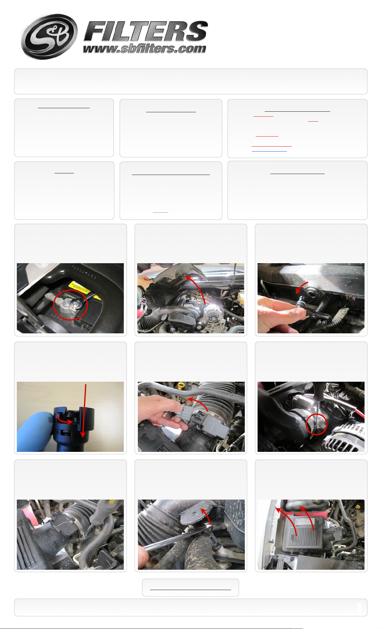
1. With the ignition switched off and the
parking brake set, disconnect the negative
battery cable on the passenger’s side.
Tools Required
Ratchet and extensions
•
10mm Socket and Wrench
•
3/16” Allen Wrench
•
5/16” Nut Driver or Flat Blade Screwdriver
•
Phillips Screwdriver
•
9/16” Wrench
•
CARB Status - Exempt
CARB EO #: D-590-8
Legal for use in CA or other states
adopting CA emissions standards
See Page 3 for more info.
2. Remove the engine cover by lifting it up
out of the grommets, then pull towards the
front of the vehicle.
Cleanable (KF-1055). If the enclosed filter is Red, it came pre-oiled
from the factory. When serviced, apply (90g) of S&B oil to the main
body of the filter.
Disposable (KF-1055D). If the enclosed filter is White, it is a
disposable filter and should be discarded once it reaches capacity.
This filter (does not require oil). For more info on S&Bʼs disposable
filter, visit www.sbfilters.com.
Before You Start
S&B Filter Maintenance
Please read the entire product guide before proceeding.
•
Ensure all components listed on page 4 are present.
•
If you are missing any of the components, call our customer
•
support at (909) 947-0015.
Do not work on your vehicle while engine is hot.
•
Make sure the engine is turned off and the vehicle is in Park or
•
the Parking Brake is set.
3. Disconnect the crank case vent line from
the intake tube plenum by gently pulling it out.
4. Disconnect the other end of the crank
case vent line from the vehicle by sliding the
locking tab over and pull away from the valve
cover port.
7. Disconnect the intake tube from the air
cleaner assembly. Then remove the intake
from the vehicle.
5. Disconnect the MAF sensor wiring
harness from the MAF sensor. Note: If
equipped, disconnect the Pressure Sensor
wiring harness (located on the air cleaner lid)
at this time as well.
8. Using a flat blade screwdriver, remove the
intake tube from the push pin located on the
coolant tube. Then remove the intake from
the vehicle.
6. Disconnect the intake tube from the
throttle body.
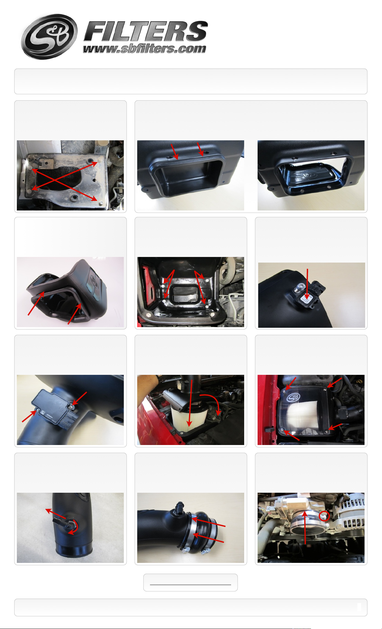
9. Remove the air cleaner box from the
vehicle by carefully pulling it up out of the
factory grommets.
SEE EXPLODED VIEW ON PAGE 4
15461 Slover Ave., Fontana, CA 92337 - Phone: (909) 947-0015 - Fax: (909) 947-0603 - www.sbfilters.com
1
Page 2
Installation Instructions (continued)
P/N: 75-5059 / 75-5059D
S&B
10. Using 10mm socket, remove the 4
bolts securing the air box tray. Then remove
the tray from the truck. Save all 4 bolts for
S&B installation.
12. Install the Air Inlet Fender Seal (C) onto
the lip of the Air Box (B).
11. For those concerned about minimal engine heat; install the Air Inlet Plug (A) into the bottom of
the Air Box (B) by pushing it down until the bead catches the lip as shown below. For those seeking
additional air flow, set the Air Inlet Plug aside. (See page 3 for more info and test results)
13. Install the Air box assembly using the
supplied M6-1.0x10mm Screws (T) and 6mm
Washers (U) in the two holes closest to the
fender and the 2 longer OE screws in the
remaining two holes.
14. If equipped with Pressure Sensor, Drill a
1/4” hole using the drill point located in the Filter
Adapter Tube (K). Be careful only to drill through one
surface (NOT all the way through the backside).
Thoroughly clean the inside of the tube of all debris.
Then install the pressure sensor using the 1/4-20
Socket Screw (L) and a 3/16” allen wrench.
OE
15. Remove the MAF sensor from the OE
air cleaner using the supplied T15 Torx key.
Install it into the Filter Adapter Tube (K) using
the supplied 8-32x1/2” Screws (J). Do not
over tighten.
18. Install the 90degree Hose Barb (P) on to
the Intake Tube (O) until it is hand tight. Then
using a 9/16” wrench turn it one more rotation
into position as shown.
16. Insert the S&B Filter (D) onto the
Adapter Tube (K) and secure the #80 Hose
Clamp (E). Install the assembly into the Air
box as shown below.
2
1
19. Place a #64 Hose clamp (M) over each
end of the Hump Coupler (N). Then slide the
hump coupler over the end of the Intake Tube
(O).
17. Install the Clear Lid (H). Secure the Lid and
Filter Adapter using the supplied 1/4”-20x1-1/4”
S.S. Screws (I) and Rubber Washers (F). Then
use the 1/4”-20x5/8” S.S. Screws (G) and
Rubber Washers (F) in the remaining two holes.
20. Secure the Silicone Step Coupler (S) to
the throttle body using a #64 Hose Clamp
(M). Place the #72 Hose Clamp (R) around
the top of the Silicone coupler.
SEE EXPLODED VIEW ON PAGE 4
15461 Slover Ave., Fontana, CA 92337 - Phone: (909) 947-0015 - Fax: (909) 947-0603 - www.sbfilters.com
2
Page 3

Installation Instructions (continued)
P/N: 75-5059 / 75-5059D
21. Insert the Intake tube assembly into the
Silicone Coupler, then slide the Hump
Coupler over the Adapter Tube. Tighten all
hose clamps when you are satisfied with the
positioning.
24. Re-install the engine cover. Inspect your
installation, make sure the kit is properly
positioned and all fasteners are secure.
22. Push the Silicone Breather Hose (Q)
over the Hose Barb (P) on the Intake tube.
Then push the other end onto the valve cover
vent line. Trim hose to desired fit if necessary.
Hose should not be resting on other parts.
25. Reconnect the battery.
The installation is now complete.
23. Reconnect the MAF sensor wiring
harness (and Pressure Sensor if equipped).
Related Items
Available at www.sbfilters.com
Precision II Filter Cleaning & Oiling Kit
•
(S&B P/N: 88-0008)
Replacement Air Filter (Oiled)
•
(S&B P/N: KF-1055)
Replacement Air Filter (Dry)
•
(S&B P/N: KF-1055D)
Air Filter Wrap
•
(S&B P/N: WF-1035)
Air Scoop
•
(S&B P/N: AS-1003)
Performance Testing
Engage parking brake and start your engine. Listen for abnormal noises. If an air leak is detected, re-inspect hoses and connections as they may need to be repositioned and
•
tightened.
S&B FILTERS recommends that you keep your OE intake system in the event it is required in the future.
•
In order to maintain your warranty, all connections and components must be checked periodically for alignment and for proper tension on all connections. Failure to do so
•
may void your warranty.
Use only S&B FILTERS cleaning and oil products to service your filter. Using any other brand oil and or cleaners on your S&B air filter may void your warranty.
•
Warning!
If your vehicle has a Vehicle Emission Control Information decal affixed to the factory airbox, a new
replacement label must be obtained and installed in a readily visible position in the engine compartment in
order to remain CARB compliant. Failure to do so will prevent the vehicle from passing a smog check.
Replacement labels can be ordered from your local dealership. Regulations state that the VECI label shall
not be affixed to any equipment which is easily detached from the vehicle. Label placement, under the hood
on a painted surface is recommended.
Air Box End Cap Testing
Stock air boxes are a significant contributor to poor air flow which is why S&B designs custom air boxes with secondary and/or enlarged openings. With
that said, S&B recognizes the benefits of cooler air, so we have included a plug to seal off the opening if so desired. For optimal performance, we
recommend that the intake be used without the end cap except in conditions of extreme heat.
The California Air Resource Board (CARB) requires that an E.O. identification label be applied to the vehicle in order to pass a smog check inspection when a Performance
Intake Kit has been installed. You must place the E.O. label provided on or near the intake kit after installation so that a smog check technician can easily verify the E.O. number.
As of April 2009, S&B has never had a product where CARB denied an exemption request; however, the exemption process with CARB can take as long as 18 months. Check
the status of the exemption process by looking up a specific part number at www.sbfilters.com. The CARB Exemption number and/or status is listed under the Product Details
section for each part number. If the status shows as “Pending,” CARB has yet to issue an exemption. Products that have not been issued an EO number are street legal in most
states, but may not be used on emission controlled vehicles in the state of California and are for off road use only. If you purchased your kit from S&B Filters directly, we will
automatically mail you your Exemption Sticker when it is issued to us. If you purchased your kit from an authorized S&B Filters Dealer, log onto our web site and register to
receive your Exemption Sticker.
SEE EXPLODED VIEW ON PAGE 4
15461 Slover Ave., Fontana, CA 92337 - Phone: (909) 947-0015 - Fax: (909) 947-0603 - www.sbfilters.com
Emissions Standard
3
Page 4

ITEM
QTY.
DESCRIPTION
P/N
A1Air Inlet Plug
AI1559-00
B1Air Box
AL1157-00
C1Air Inlet Fender Seal
AI1550-00
D1S&B Air Filter
KF-1055E1
Hose Clamp, #80
AG1010-00
F4Rubber Sealing Washer, 1/4”
AI1571-00
G2Screw, Truss Head, 1/4-20x5/8”
AI1569-00
H1Clear Lid
AI1513-00
I2Screw, Truss Head, 1/4-20x1.25”
AI1568-00
J2Screw, Phillips Head, 8-32x1/2”
AI1479-00
K1Filter Adapter Tube
AL1158-00
L1Screw, Socket Head, 1/4-20x7/8”
AI1570-00
M3Hose Clamp, #64
AG1018-00
N1Hump Coupler, 3.875”x3.00” Long
AI1551-00
ITEM
QTY.
DESCRIPTION
P/N
O1Intake Tube
AL1159-00
P1Hose Barb, 3/8”x1/4”npt, 90degree
AI1307-00
Q1Silicone Breather Tube, 18”
AI1572-01
R1Hose Clamp, #72
AG1009-00
S1Silicone Step Coupler,
AI1542-00
T2Screw, Hex Head, M6-1.0x30mm
AI1257-00
U2Washer, Flat, 6mm
AI1535-00
Exploded View
AM0185-00 Rev.D 10/01/13
P/N: 75-5059 / 75-5059D
Warranty
Visit www.sbfilters.com/Support/Why-S-B/Million-Mile-Limited-Warranty for S&B Filterʼs complete warranty.
15461 Slover Ave., Fontana, CA 92337 - Phone: (909) 947-0015 - Fax: (909) 947-0603 - www.sbfilters.com
4
 Loading...