

Page 1
Installation Instructions
P/N: 75-5054 / 75-5054D
Vehicle Application
Year: 2008-10
Make: FORD
Model: F-250, F-350, F-450, F-550
Engine: 6.4L Power Stroke
Notes
Kit may not fit with the following
Aftermarket Parts installed:
Body Lift or Lowering Kit
•
Custom Hood
•
Intercooler or Turbo upgrades
•
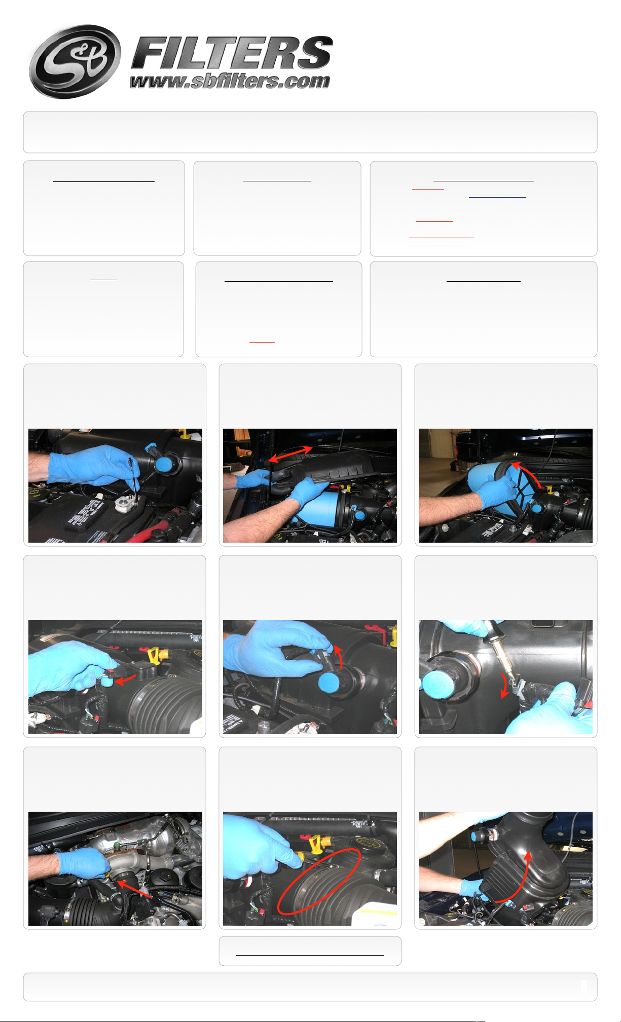
1. With the ignition switched off and the
parking brake set, disconnect the negative
battery cables on both batteries using a 8mm
wrench or socket.
8mm &10mm Wrench & Socket
•
T-20 Security Torx Wrench (Supplied w/ Kit)
•
5/16” Nut Driver or Flat Blade Screwdriver
•
Phillips Screwdriver, Pliers or Channel locks
•
CARB Status - Pending
Tools Required
Product has been submitted to Air
Resources Board for approval.
Not Legal for use in CA or other states
adopting CA emissions standards
See Page 3 for more info.
2. Unclip the OE air box lid and pull the hot
air supply tube out and remove the lid.
Cleanable (KF-1052). If the enclosed filter is Red, it came pre-oiled
from the factory. Please visit www.sbfilters.com for exact oil
amount required after cleaning.
Disposable (KF-1052D). If the enclosed filter is White, it is a
disposable filter and should be discarded once it reaches capacity.
This filter (does not require oil). For more info on S&Bʼs disposable
filter, visit www.sbfilters.com.
Before You Start
S&B Filter Maintnance
Please read the entire product guide before proceeding.
•
Ensure all components listed on page 4 are present.
•
If you are missing any of the components, call our customer
•
support at (909) 947-0015.
Do not work on your vehicle while engine is hot.
•
Make sure the engine is turned off and the vehicle is in Park or
•
the Parking Brake is set.
3. Remove the OE air filter from the air box.
4. Disconnect the electrical connection from
the MAF sensor at the OE air box.
7. Loosen the OE hose clamp at the turbo
inlet.
5. Disconnect the electrical connection from
the OE restriction gauge. Note: Do not rely on
OE restriction gauge or until the dash light is
triggered before you service your S&B filter.
8. Loosen the OE hose clamp at the air box
connection.
6. Use a flathead screwdriver to pry the
wire loom retaining clip from the OE air box.
9. OE air box Removal: Grasp the air box at
the end and lift up, separating the prongs
from the grommets at the bottom of the box.
SEE EXPLODED VIEW ON PAGE 4
15461 Slover Ave., Fontana, CA 92337 - Phone: (909) 947-0015 - Fax: (909) 947-0603 - www.sbfilters.com
1
Page 2
Installation Instructions (continued)
P/N: 75-5054 / 75-5054D
10. Use a flathead screwdriver to pry open
the OE hose clamp securing the crankcase
vent hose to the intake tube. Discard clamp.
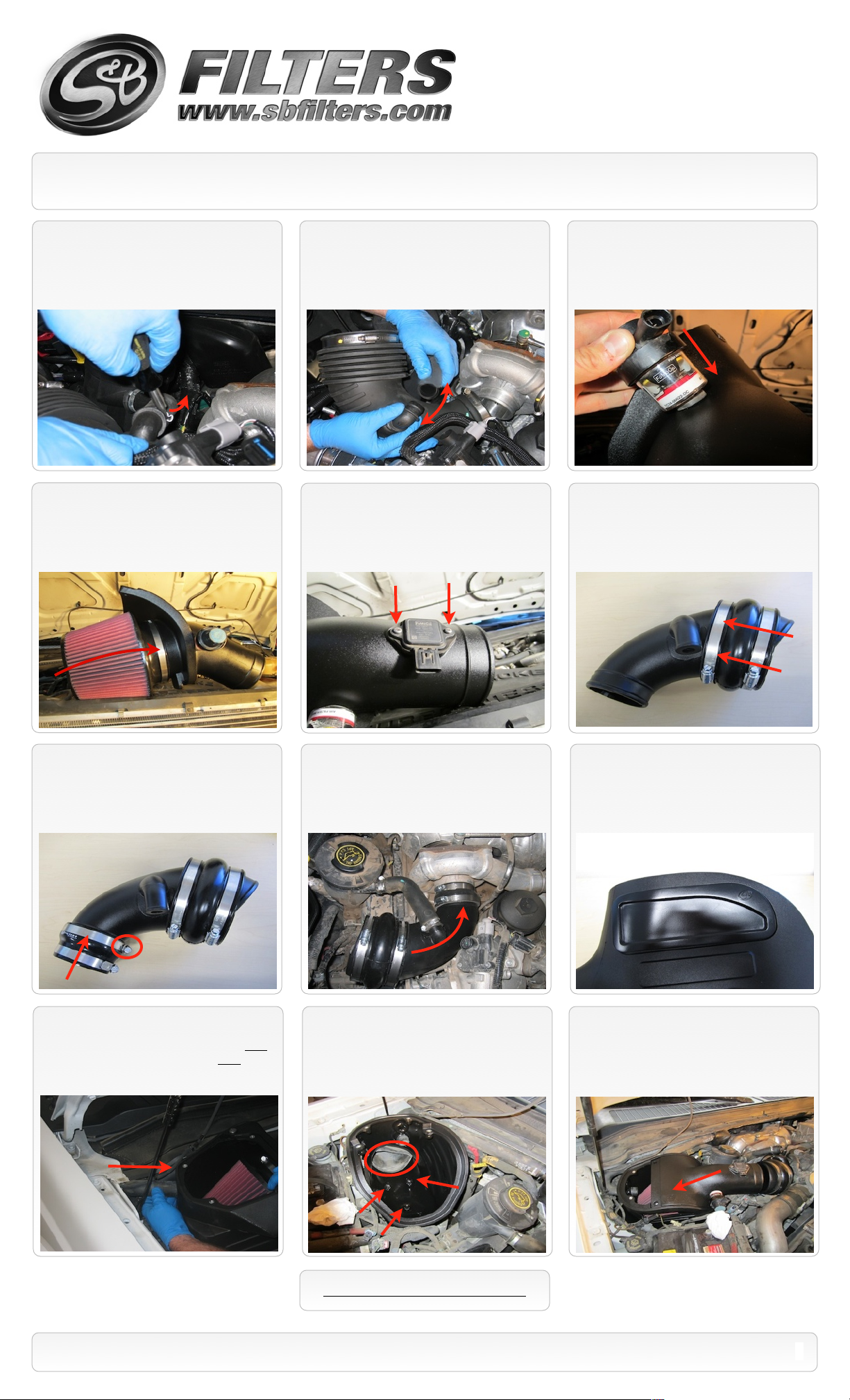
13. Attach the S&B Filter (E) to the Filter
Adapter (G), secure with the #80 hose clamp
(F).
11. Separate the vent hose from the intake
tube and remove intake tube from the vehicle.
14. Remove the MAF sensor for the OE
cover and attach the MAF sensor to the Filter
Adapter (G). Use the MAF Gasket (I) and the OE
screws. For 2009 models use the supplied M4
screws (Q). Do not over tighten!
12. Remove the OE filter gauge and rubber
grommet and insert the grommet into the
Filter Adapter (G), then insert the filter gauge.
15. Place two #72 hose clamps (J) over the
Hump Adapter (K) and slide the Hump
Adapter over the Intake Tube (L) until it is
flush with the end.
16. Place a #52 hose clamp (N) and a #56
hose clamp (P) on the Step Adapter (O) and
secure the larger end to the intake tube.
19. Place Air Box (H) in the area of the
installation and insert the OE hot air into Plug
for warm weather conditions or the Hole for
cold weather conditions.
17. Push the small end of the Intake tube
assembly over the turbo inlet. Leave the
connection loose for now.
20. Install the Air Box (H) by placing the box
at an angle so that it secures around the OE
air inlet on the inner fender. Then push down
until the 3 prongs slide into the OE rubber
grommets. Use grease if necessary.
18. For those concerned about minimal
engine heat; insert the Box Plug (R) into the
side of the Air Box (H). For those seeking
additional air flow, set the Box Plug aside.
(See page 3 for more info)
21. Place the Filter assembly into the Air
Box (H), hook the bottom into the lip on the
Air Box.
SEE EXPLODED VIEW ON PAGE 4
15461 Slover Ave., Fontana, CA 92337 - Phone: (909) 947-0015 - Fax: (909) 947-0603 - www.sbfilters.com
2
Page 3

Installation Instructions (continued)
P/N: 75-5054 / 75-5054D
22. Center the Hump adapter (K) over the
gap between tube ends and secure both #72
hose clamps (J). Then tighten the #52 hose
clamp (N) at the turbo.
25. Reconnect the MAF sensor and
restriction gauge electrical connections.
23. Use the #16 hose clamp (M) to secure
the crank case breather vent line to the Intake
Tube (L). It may be necessary to remove the
other OE clamp and reposition the line. Then
you will use the other #16 clamp and secure.
26. Reconnect both batteries. Inspect your
installation, make sure the kit is properly
positioned and all fasteners are secure. Affix
the CARB sticker near the intake kit. The
installation is now complete.
24. Remove the protective film from both
sides of the Clear Lid (D), place the lid on the air
box and secure using the supplied 10-24 screws
(B) with sealing washers (C) and 5/16” Screws
(A) with Rubber washers (S).
Related Items For Your Purchase
Replacement Air Filter (Oiled)
•
(S&B P/N: KF-1051)
Replacement Air Filter (Dry)
•
(S&B P/N: KF-1051D)
Air Filter Wrap (S&B P/N: WF-1022)
•
Performance Testing
Engage parking brake and start your engine. Listen for abnormal noises. If an air leak is detected, re-inspect hoses and connections as they may need to be repositioned and
•
tightened.
S&B FILTERS recommends that you keep your OE intake system in the event it is required in the future.
•
In order to maintain your warranty, all connections and components must be checked periodically for alignment and for proper tension on all connections. Failure to do so
•
may void your warranty.
Use only S&B FILTERS cleaning and oil products to service your filter. Using any other brand oil and or cleaners on your S&B air filter may void your warranty.
•
Air Box End Cap Testing
Stock air boxes are a significant contributor to poor air flow which is why S&B designs custom air boxes with secondary and/or enlarged openings. With that said, S&B
recognizes the benefits of cooler air, so we have included a plug to seal off the opening if so desired. For optimal performance, we recommend that the intake be used without
the end cap except in conditions of extreme heat.
Warning!
If your vehicle has a Vehicle Emission Control Information decal affixed to the factory airbox, a new
replacement label must be obtained and installed in a readily visible position in the engine compartment in
order to remain CARB compliant. Failure to do so will prevent the vehicle from passing a smog check.
Replacement labels can be ordered from your local dealership. Regulations state that the VECI label shall
not be affixed to any equipment which is easily detached from the vehicle. Label placement, under the hood
on a painted surface is recommended.
Emissions Standard
The California Air Resource Board (CARB) requires that an E.O. identification label be applied to the vehicle in order to pass a smog check inspection when a Performance
Intake Kit has been installed. You must place the E.O. label provided on or near the intake kit after installation so that a smog check technician can easily verify the E.O. number.
As of April 2009, S&B has never had a product where CARB denied an exemption request; however, the exemption process with CARB can take as long as 18 months. Check
the status of the exemption process by looking up a specific part number at www.sbfilters.com. The CARB Exemption number and/or status is listed under the Product Details
section for each part number. If the status shows as “Pending,” CARB has yet to issue an exemption but the product has been submitted. Products that have not been issued an
EO number are street legal in most states, but may not be used on emission controlled vehicles in the state of California and are for off road use only. If you purchased your kit
from S&B Filters directly, we will automatically mail you your Exemption Sticker when it is issued to us. If you purchased your kit from an authorized S&B Filters Dealer, log onto
our web site and register to receive your Exemption Sticker.
SEE EXPLODED VIEW ON PAGE 4
15461 Slover Ave., Fontana, CA 92337 - Phone: (909) 947-0015 - Fax: (909) 947-0603 - www.sbfilters.com
3
Page 4

ITEM
QTY.
DESCRIPTION
P/NA2
S.S. Screw, 5/16-18 x 1.0”
AI1297-00
B2S.S. Screw, 10-24 x 1/2”
AI1287-00
C2S.S. Sealing Washer, 10-24
AI1272-00
D1Clear Box Lid
AI1508-00
E1S&B Air Filter
KF-1051F1
Hose Clamp, #88
AG1011-00
G1Filter Adapter Tube
AL1155-00
H1Air Box
AL1154-00
I1MAF Sensor Gasket
AI1345-00
J2Hose Clamp, #72
AG1009-00
K1Hump Adapter
AI1462C-00
L1Intake Tube
AL1156-00
M2Hose Clamp, #16
AG1001-00
N1Hose Clamp, #52
AG1007-00
ITEM
QTY.
DESCRIPTION
P/NO1
Silicone Step Adapter
AI1316S-01
P1Hose Clamp, #56
AG1019-00
Q2S.S. Screw, M4-0.7x10mm
AL1107-00
R1Box Plug
AI1510-00
S2Rubber Washer
AI1435-00
Exploded View
AM0169-00 Rev.E 09/24/13
P/N: 75-5054 / 75-5054D
Warranty
Visit www.sbfilters.com for complete warranty information.
15461 Slover Ave., Fontana, CA 92337 - Phone: (909) 947-0015 - Fax: (909) 947-0603 - www.sbfilters.com
4
 Loading...