

Page 1
INSTALLATION INSTRUCTIONS
P/N: 75-5050 / 75-5050D
VEHICLE APPLICATION
Year: 2009-10
Make: Ford / Lincoln
Model: F150,Expedition,
Navigator
Engine: 5.4L
NOTES
Kit may not fit with the following
Aftermarket Parts Installed:
Body Lift
•
Custom Hood
•
Throttle Body Upgrade
•
Throttle Body Spacer
•
We have provided a small tube of thread locker in
your kit. Whenever you see the symbol above on a step
of the instructions apply 1 small drop of the thread locker
to the threads of the screws or bolts. This will keep your
hardware from vibrating loose during rough driving. If the
hardware ever needs to be removed, do so slowly to
avoid having the inserts strip out from the plastic. DO
NOT USE ON LID HARDWARE.
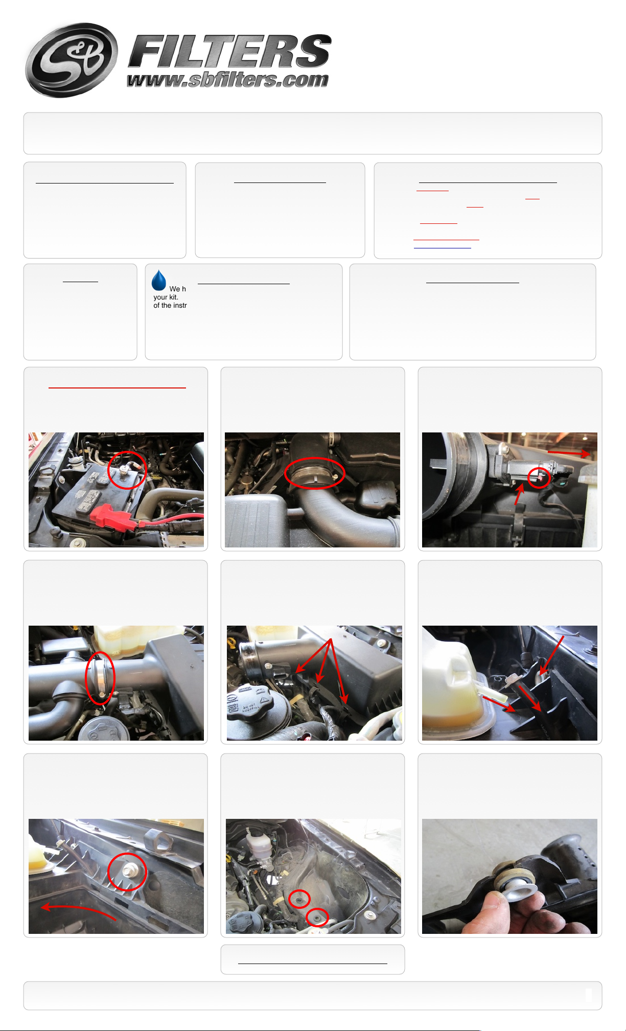
1. Be sure engine is cool before starting!
With the ignition switched off and the parking
brake set, disconnect the negative battery
cable.
TOOLS REQUIRED
10mm, 13mm, 5/16” Wrench or Socket
•
Phillips head Screwdriver
•
5/16” Nut Driver or Flat Blade Screwdriver
•
Teflon tape
•
Ford approved engine coolant (To top off new
•
coolant reservoir if needed)
Thread Locker Use
2. Loosen the hose clamp at the throttle
body.
Cleanable (KF-1035). If the enclosed filter is Red, it came pre-
oiled from the factory. When serviced, apply (87g) of S&B oil to the
main body of the filter and (17g) to the Power Stack (Top).
Disposable (KF-1035D). If the enclosed filter is White, it is a
disposable filter and should be discarded once it reaches capacity.
This filter (does not require oil). For more info on S&Bʼs disposable
filter, visit www.sbfilters.com.
BEFORE YOU START
Please read the entire product guide before proceeding.
•
Ensure all components listed on page 4 are present.
•
If you are missing any of the components, call our customer support
•
at (909) 947-0015.
Do not work on your vehicle while engine is hot.
•
Make sure the engine is turned off and the vehicle is in Park or the
•
Parking Brake is set.
3. Disconnect the MAF sensor by sliding
the red locking pin back, press in the bottom
of the harness and pull out the male
connection.
S&B FILTER MAINTENANCE
4. Loosen the hose clamp at the air box/
intake tube connection. Then remove the
intake tube assembly from the truck.
7. Remove the other air box mounting bolt
using 13mm socket. Carefully tip the air box
assembly away from the fender so that
coolant isnʼt spilt.
5. Undo the three clips holding the air box
cover to the air box. Remove the air box lid
and air filter from the truck.
8. Pull the assembly out of the factory
grommets and remove from truck. Note: You
will have to remove the bolt from the rubber
tube to fit through the air box assembly.
6. Using a 13mm socket, remove the rear
air box mounting bolt. Then carefully remove
the coolant overflow tube from the reservoir
and use the mounting bolt as a temporary
plug for the tube.
9. Remove the mounting insert and rubber
grommet from the OE air box assembly.
SEE EXPLODED VIEW ON PAGE 5
15461 Slover Ave., Fontana, CA 92337 - Phone: (909) 947-0015 - Fax: (909) 947-0603 - www.sbfilters.com
1
Page 2
INSTALLATION INSTRUCTIONS (Continued)
P/N: 75-5050 / 75-5050D
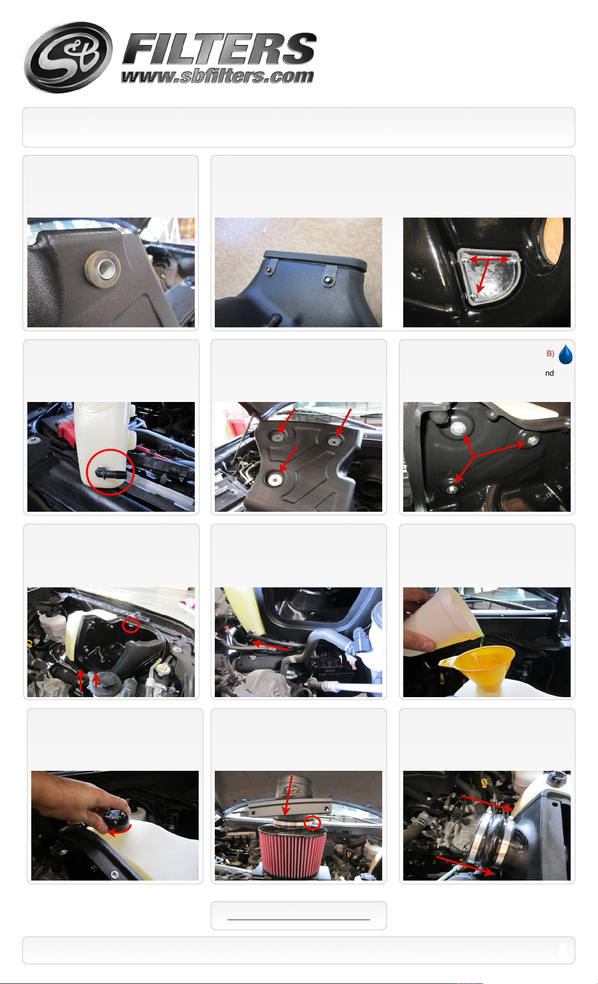
10. Insert the OE rubber grommet and insert
to the Air Box (A) as shown.
12. Apply Teflon tape to the threads of the
90deg. Hose Barb (E). Insert the Hose Barb
into the Coolant Recovery Tank (B) as shown.
Be sure the connection is tight.
11. For those concerned about minimal engine heat; insert the three Clip Nuts (T) over the holes
on the bottom opening of the Air Box (A), insert the Box Plug (U) into the end of the Air Box (A).
Attach using the supplied 1/4-20 Hex Screws (V) and Flat Washers (Y) from the inside of the Air box
using 5/16” socket or ratcheting wrench. For those seeking additional air flow, set the Air Box End
Cap aside. (See page 4 for more info)
13. Place the three Large Fender Washers
(X) into the indents on the side of the Air Box
(A).
14. Place the Coolant Recovery Tank (B)
on the side of the Air Box (A). Attach it
using the supplied 5/16” Hex Bolts (D) and
5/16” Flat Washers (C).
15. Install the Air Box/ Coolant Tank
assembly into the truck. Push the prongs on
the bottom of the air box into the OE
grommets set in the frame. Secure the using
the OE bolt removed in Step #7.
18. Attach the Reservoir Cap (W) to the
Recovery Tank (B).
16. Remove the OE bolt that was inserted
into the rubber coolant tube in Step #6 and
push the tube end over the end of the 90deg.
Hose Barb (E).
19. Insert the Adapter Tube (F) to the S&B
Air Filter (G) as shown. Tighten the #80 Hose
Clamp (H).
17. Remove the coolant from the OE reservoir
and pour it into the Coolant Recovery Tank (B).
Note: It may be necessary to add coolant to meet
fill range of the new tank. Be sure to use Ford
approved coolant. (See Page 4 for more info)
20. Slide the Filter assembly into the Air
Box. Install two #80 Hose Clamps (H) over
the Hump Adapter (Q). Push the Hump hose
over the end of the Adapter Tube (F).
SEE EXPLODED VIEW ON PAGE 5
15461 Slover Ave., Fontana, CA 92337 - Phone: (909) 947-0015 - Fax: (909) 947-0603 - www.sbfilters.com
2
Page 3

INSTALLATION INSTRUCTIONS (Continued)
P/N: 75-5050 / 75-5050D
21. Install the small end of the Silicone
Adapter (R) over the throttle body outlet.
Secure using a #56 Hose Clamp (J). Loosely
slide the #60 Hose Clamp (I) around the
opposite end.
24. Install the supplied MAF sensor
extension harness (Z) between the MAF
sensor and the OE MAF connector. Use the
supplied wire tie to position the harness away
from any potential hazards.
22. Remove the MAF sensor from the OE
air box lid using the supplied Torx tool. With
the small rubber OE ring gasket in place,
install the MAF sensor into the Intake Tube
(P) using the M4 Screws (S).
25. Remove the protective covering from
the Clear Lid (K), then install the lid. Secure
using the four 10/24” Screws (O), Sealing
Washers (N), and two 5/16” Screws (M) and
Rubber washers (L). Do not over tighten.
23. Install the Intake Tube (P) into the
Silicone Adapter (R) and then slide the Hump
Adapter (Q) over the opposite end. Secure all
the hose clamps at this time.
26. Reconnect the battery. Inspect your
installation, make sure the kit is properly
positioned and all fasteners are secure. The
installation is now complete.
ATTENTION: DO NOT USE THREAD
LOCKER ON THESE SCREWS. VAPORS
CAN CAUSE CRACKING ON LIDS.
SEE EXPLODED VIEW ON PAGE 5
15461 Slover Ave., Fontana, CA 92337 - Phone: (909) 947-0015 - Fax: (909) 947-0603 - www.sbfilters.com
3
Page 4

EMISSIONS STANDARD
The California Air Resource Board (CARB) requires that an E.O. identification label be applied to the vehicle in order to pass a smog
check inspection when a Performance Intake Kit has been installed. You must place the E.O. label provided on or near the intake kit
after installation so that a smog check technician can easily verify the E.O. number. As of April 2009, S&B has never had a product
where CARB denied an exemption request; however, the exemption process with CARB can take as long as 18 months. Check the
status of the exemption process by looking up a specific part number at www.sbfilters.com. The CARB Exemption number and/or
status is listed under the Product Details section for each part number. If the status shows as “Pending,” CARB has yet to issue an
exemption. Products that have not been issued an EO number are street legal in most states, but may not be used on emission
controlled vehicles in the state of California and are for off road use only. If you purchased your kit from S&B Filters directly, we will
automatically mail you your Exemption Sticker when it is issued to us. If you purchased your kit from an authorized S&B Filters Dealer,
log onto our web site and register to receive your Exemption Sticker.
INSTALLATION INSTRUCTIONS (Continued)
P/N: 75-5050 / 75-5050D
Air Box End Cap Testing
Stock air boxes are a significant contributor to poor air flow which is why S&B designs custom air boxes with
secondary and/or enlarged openings. With that said, S&B recognizes the benefits of cooler air, so we have included a
plug to seal off the opening if so desired. For optimal performance, we recommend that the intake be used without
the end cap except in conditions of extreme heat.
ISO 5011 Test Data:
With the end cap installed, the intake improves airflow by an average of 37.2% versus stock.
Without the end cap installed, the improvement increases to an average of 61.2%.
Important Coolant Note
USE ONLY MOTORCRAFT PREMIUM GOLD COOLANT OR EQUIVALENT.
MIX 50 / 50 WITH DISTILLED WATER.
DO NOT ADD ORANGE COLORED COOLANT SUCH AS DEXCOOL BRAND.
SEE OWNERS MANUEL FOR ADDITIONAL INFORMATION
Precision II
Filter Cleaning & Oiling
Order online today at www.sbfilters.com or
through your local S&B distributor.
Part #: 88-0008
RELATED ITEMS FOR YOUR
PURCHASE
Ram Air Scoop (S&B P/N: 75-5067)
•
Replacement Air Filter (Oiled)
•
(S&B P/N: KF-1035)
Replacement Air Filter (Dry)
•
(S&B P/N: KF-1035D)
Air Filter Wrap (S&B P/N: WF-1024)
•
SEE EXPLODED VIEW ON PAGE 5
PERFORMANCE TESTING
Engage parking brake and start your engine.
•
Listen for abnormal noises. If an air leak is
detected, re-inspect hoses and connections as
they may need to be repositioned and
tightened.
S&B FILTERS recommends that you keep
•
your OE intake system in the event it is
required in the future.
In order to maintain your warranty, all
•
connections and components must be
checked periodically for alignment and for
proper tension on all connections. Failure to
do so may void your warranty.
Use only S&B FILTERS cleaning and oil
•
products to service your filter. Using any other
brand oil and or cleaners on your S&B air filter
may void your warranty.
15461 Slover Ave., Fontana, CA 92337 - Phone: (909) 947-0015 - Fax: (909) 947-0603 - www.sbfilters.com
4
Page 5

ITEM
QTY.
DESCRIPTION
P/NA1
Air Box
AL1142-00
B1Coolant Recovery Tank
AL1143-00
C3Washer, Flat, 5/16”
AI1093-00
D3Hex Head Bolt, 5/16-18 x 3/4”
AI1467-00
E1Hose Barb, 90deg. 1/4”NPT
AI1307-00
F1Adapter Tube
AL1141-00
G1S&B Filter
KF-1035H3
Hose Clamp, #80
AG1010-00
I1Hose Clamp, #60
AG1008-00
J1Hose Clamp, #56
AG1019-00
K1Clear Lid
AI1482-00
L2Rubber Sealing Washer, 5/16”
AI1434-00
M2Truss Screw, 5/16-18 x 1”
AI1297-00
N4SS Sealing Washer, #10
AI1272-00
EXPLODED VIEW
AM0171-00 Rev.E 11/05/12
P/N: 75-5050 / 75-5050D
ITEM
QTY.
DESCRIPTION
P/NO4
Pan Head Screw, 10-24 x 1/2”
AI1287-00
P1Intake Tube
AL1140-00
Q1Hump Hose, 5.0”ID
AI1338-00
R1Silicone Step Adapter
AI1489S-00
S2Pan Screw, M4x0.7x8mm
AI1360-00
T3Clip Nut, #1/4-20
AI1059-00
U1Box Plug
AL1147-00
V3Hex Head Screw, 1/4-20 x 1.0”
AI1131-00
W1Cap, Coolant Reservoir
AI1526-00
X3Fender Washer, 1.25”OD
AI1080-00
Y3Washer, Flat, M6
AI1535-00
Z1MAF Wiring Harness Extension
(not pictured)
AI1481-00
15461 Slover Ave., Fontana, CA 92337 - Phone: (909) 947-0015 - Fax: (909) 947-0603 - www.sbfilters.com
5
 Loading...