

Page 1
INSTALLATION INSTRUCTIONS
P/N: 75-5045 / 75-5045D
VEHICLE APPLICATION
Year: 1992-00
Make: Chevy / GMC
Model: C/K 1500-3500 w/o MAF
Engine: 6.5L Diesel
*Will not fit 97-98 vehicles equipped with
MAF sensor
NOTES
Kit may not fit with the following
Aftermarket Parts Installed:
Body Lift
•
Custom Hood
•
Intercooler or Turbo Upgrades
•
Larger Battery Group #
•
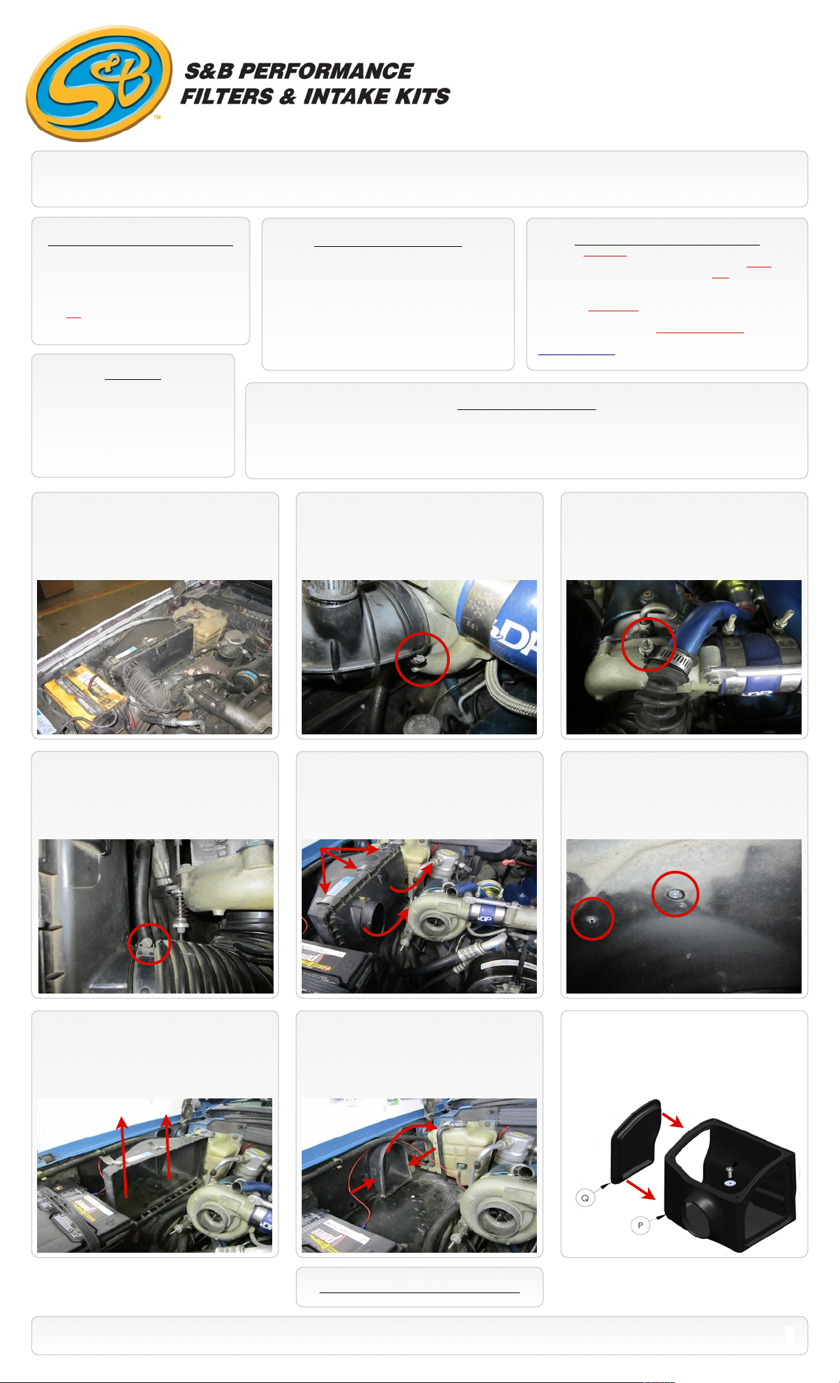
1. Turn off the truck and set the parking
break. Do NOT disconnect the battery
terminals.
TOOLS REQUIRED
9/16” Wrench or Socket
•
Phillips head Screwdriver
•
5/16” Nut Driver or Flat Blade Screwdriver
•
7/32” Allen Wrench
•
S&B FILTER MAINTENANCE
Cleanable (KF-1047). If the enclosed filter is Red, it came
pre-oiled from the factory. When serviced, apply (104g) of
S&B oil to the main body of the filter and (4g) to the Power
Stack (Top).
Disposable (KF-1047D). If the enclosed filter is White, it is a
disposable high flow filter and should be discarded once it
reaches capacity. This filter (does not require oil). For more
info on extending the life of S&Bʼs disposable filter, visit
www.sbfilters.com.
BEFORE YOU START
Please read the entire product guide before proceeding.
•
Ensure all components listed on page 4 are present.
•
If you are missing any of the components, call our customer support at (909) 947-0015.
•
Do not attempt to work on your vehicle while engine is hot.
•
Make sure the engine is turned off and the vehicle is in Park or the Parking Brake is set.
•
2. Loosen the hose clamp at the turbo.
3. Loosen the hose clamp on the crankcase
vent tube (CVT).
4. Loosen the clamp at the tube/ air box
connection. Then remove the tube assembly
from the truck.
7. Remove the air box from the truck.
5. Unclip the air box cover from the air box.
Remove the cover and filter from the truck.
8. Remove the OE snorkel from the fender
by pressings in the sides and popping it out
towards the motor.
6. From under the wheel well, remove the 2
bolts mounting the air box.
9. For those concerned about engine heat,
insert the Air Box End Cap (Q) into the
end of the Air Box (P). For those seeking
additional air flow, set the Air Box End
Cap aside. (See page 3 for more info)
SEE EXPLODED VIEW ON PAGE 4
15461 Slover Ave., Fontana, CA 92337 - Phone: (909) 947-0015 - Fax: (909) 947-0603 - www.sbfilters.com
1
Page 2
INSTALLATION INSTRUCTIONS (Continued)
P/N: 75-5045 / 75-5045D
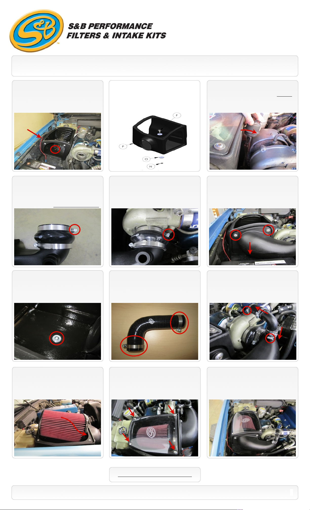
10. Place the Air Box (P) into the truck. Line
the hole in the bottom of the box to the hole
on top of the wheel liner. Position the air inlet
of the box into the hole in the fender.
12. Install the Silicone Turbo Adapter (H) to
the Intake Tube (L). Install the larger ID end
on the tube using the #56 Hose clamp (I).
Place the #52 Hose Clamp (G) on the smaller
end of the adapter. *Note the clamp position*
Small ID
11. Loosely install the Air Box (P) to the
wheel liner using the supplied 3/8”x1.0”
Button Head screw (F) and Fender Washer
(O) on top and the 3/8” Nylock Nut (N) and
Fender Washer in the wheel well.
13. Install the intake tube assembly onto the
turbo first and tighten the #52 Hose Clamp
(G) at the turbo.
Note: For C/K models 1996-00:
(If equipped) It may be necessary to carefully
bend the mounting tabs on waste gate
vacuum canister to clear the new Air Box.
14. Hook the latch on the Intake Tube (L) to
the bottom edge of the Air Box (P). Secure
the tube to the box using the 2 supplied 3/8”
Truss Screws (M).
Large ID
15. When you are satisfied with the
positioning of the box, tighten the hardware
mounting the box to the wheel liner.
18. Completely loosen the clamp (E)
around the Air filter base. Then carefully place
the Air Filter (D) (base end first) inside the Air
Box (P). Push the base of the filter over the
Intake Tube (L) and tighten the hose clamp.
16. Install the 2 #16 Hose Clamps (J) on
each end of the Silicone CVT Elbow (K).
19. Remove the protective covering from the
Clear Lid (C), then install the lid. Secure with
the 10/24” Screws (A) and Sealing Washers
(B). Do not over tighten.
17. With the 2 #16 Hose Clamps in place,
slip the longer hose end of the assembly onto
the OE vent tube and then push the smaller
hose end onto the intake tube. Fully tighten
the all hose clamps.
20. Inspect your installation, make sure the
kit is properly positioned and all fasteners are
secure. Affix the CARB sticker near the
intake kit. The installation is now complete.
SEE EXPLODED VIEW ON PAGE 4
15461 Slover Ave., Fontana, CA 92337 - Phone: (909) 947-0015 - Fax: (909) 947-0603 - www.sbfilters.com
2
Page 3

EMISSIONS STANDARD
The California Air Resource Board (CARB) requires that an E.O. identification label be applied to the vehicle in order to pass a smog
check inspection when a Performance Intake Kit has been installed. You must place the E.O. label provided on or near the intake kit
after installation so that a smog check technician can easily verify the E.O. number. As of April 2009, S&B has never had a product
where CARB denied an exemption request; however, the exemption process with CARB can take as long as 18 months. Check the
status of the exemption process by looking up a specific part number at www.sbfilters.com. The CARB Exemption number and/or
status is listed under the Product Details section for each part number. If the status shows as “Pending,” CARB has yet to issue an
exemption. Products that have not been issued an EO number are street legal in most states, but may not be used on emission
controlled vehicles in the state of California and are for off road use only. If you purchased your kit from S&B Filters directly, we will
automatically mail you your Exemption Sticker when it is issued to us. If you purchased your kit from an authorized S&B Filters Dealer,
log onto our web site and register to receive your Exemption Sticker.
INSTALLATION INSTRUCTIONS (Continued)
P/N: 75-5045 / 75-5045D
Air Box End Cap Testing
Stock air boxes are a significant contributor to poor air flow which is why S&B designs custom air boxes with
secondary and/or enlarged openings. With that said, S&B recognizes the benefits of cooler air, so we have included a
plug to seal off the opening if so desired. For optimal performance, we recommend that the intake be used without
the end cap except in conditions of extreme heat.
ISO 5011 Test Data:
With the end cap installed, the intake improves airflow by an average of 26.9% versus stock.
Without the end cap installed, the improvement increases to an average of 44.4%.
PRECISION
FILTER CLEANING & OILING
Part No. 88-0005
Order online today at www.sbfilters.com or
through your local S&B distributor.
RELATED ITEMS FOR YOUR
PURCHASE
Replacement Air Filter (Oiled)
•
(S&B P/N: KF-1047)
Replacement Air Filter (Dry)
•
(S&B P/N: KF-1047D)
Air Filter Wrap (S&B P/N: WF-1030)
•
SEE EXPLODED VIEW ON PAGE 4
PERFORMANCE TESTING
Engage parking brake and start your engine.
•
Listen for abnormal noises. If an air leak is
detected, re-inspect hoses and connections as
they may need to be repositioned and
tightened.
S&B FILTERS recommends that you keep
•
your OE intake system in the event it is
required in the future.
In order to maintain your warranty, all
•
connections and components must be
checked periodically for alignment and for
proper tension on all connections. Failure to
do so may void your warranty.
Use only S&B FILTERS cleaning and oil
•
products to service your filter. Using any other
brand oil and or cleaners on your S&B air filter
may void your warranty.
15461 Slover Ave., Fontana, CA 92337 - Phone: (909) 947-0015 - Fax: (909) 947-0603 - www.sbfilters.com
3
Page 4

ITEM
QTY.
DESCRIPTION
P/NA4
S.S. Screw, 10-24 x 1/2”
AI1287-00
B4S.S. Sealing Washer, 10-24
AI1272-00
C1Clear Lid
AI1495-00
D1S&B Air Filter
KF-1047E1
Hose Clamp, #64
AG1018-00
F
1
Button Head Screw, 3/8-16x1.0”
AI1497-00
G1Hose Clamp, #52
AG1007-00
H1Silicone Turbo Adapter
AI1440-00
I1Hose Clamp, #56
AG1019-00
J2Hose Clamp, #16
AG1001-00
K1Silicone CVT Elbow
AI1516-00
L1Intake Tube
AI1119-00
M2S.S. Screw, 5/16-18x1.0”
AI1297-00
N1Nylock Hex Nut, 3/8-16
AI1498-00
EXPLODED VIEW
P/N: 75-5045 / 75-5045D
ITEM
QTY.
DESCRIPTION
P/NO2
Fender Washer, 3/8” x 1.25”
AI1183-00
P1Air Box
AL1120-00
Q1Air Box End Cap
AI1441-00
AM0162-00 Rev.E 08/11/11
15461 Slover Ave., Fontana, CA 92337 - Phone: (909) 947-0015 - Fax: (909) 947-0603 - www.sbfilters.com
4
 Loading...