

Page 1
INSTALLATION INSTRUCTIONS
INSTALLATION INSTRUCTIONS
P/N 75-5044
1994-2002 Dodge
Ram 2500 & 3500
5.9L Cummins Turbo Diesel
∗ Kit may not fit vehicles with the following
Aftermarket Parts installed.
∗ Body Lift
∗ Custom Hood
∗ Turbo Upgrade
∗ Intercooler Upgrades
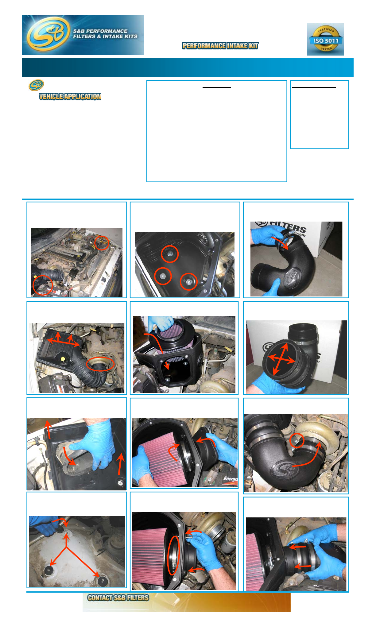
1. With the ignition switched off, place
vehicle in Park and or set Parking Brake.
Then disconnect both negative battery
cables.
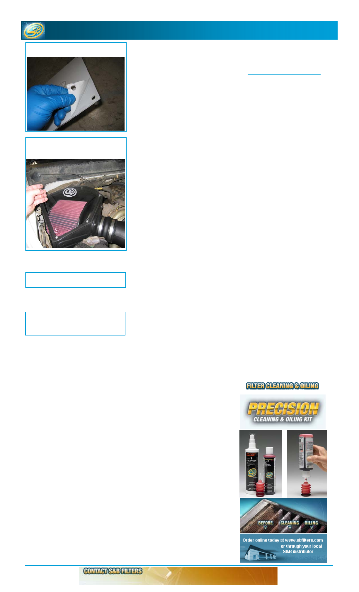
5. Determine whether your vehicle has SAE or
Metric threaded studs and use the appropriate
1/4-20(F) or M6(L) lock nuts supplied and fender
washers to secure the S&B air box (H) to the
inner fender.
PARTS LIST
QTY DESCRIPTION QTY DESCRIPTION
1 (P) Intake Tube 1 (E) # 80 Hose Clamp
1 (H) Air Box 3 (K) # 72 Hose Clamp
1 (I) Air Box Adapter 1 (M) # 64 Hose Clamp
1 (D) Air Filter 2 (J) 5/16-18 SS Screw
1 (Q) Hump Adapter 1 (C) Clear Lid
1 (N) Step Adapter 5 (B) SS Concave Washer
3 (F) 1/4-20 Lock Nut 5 (A) SS 10/24 Phillips Screw
3 (L) M6 Lock Nut 3 (G) Fender Washer
3 (R) Rubber Spacer
9. Slide the Step Adapter (N) over the small
end of the S&B Intake Tube (P) and secure the
# 72 Hose Clamp (K).
TOOLS REQUIRED
10mm Wrench or Socket
13mm Wrench or Socket
5/16” Nut driver or
Flat Blade Screwdriver
Phillips Screwdriver
Your S&B Air Filter P/N
KF-1035 is factory oiled
and ready to use.
When serviced it will
require 87g (main body)
plus 17g (top) of S&B
Filter Oil.
2. Loosen the hose clamp at the turbo inlet,
then unclip the air box top and remove the
OE intake tube and air filter.
3. Remove the restrictive factory air inlet
from the inner fender then pull up to remove
the air box from the vehicle.
6. Place the S&B air filter (D) into the S&B air
box (H).
7. Attach the S&B Filter Adapter (I) to the S&B
Air box (H) while slipping the air filter over the
flange at the same time.
10. Slide the Hump Adapter (Q) over the large
end of the S&B Intake Tube (P) until almost
flush with the end of the tube.
11. Install the S&B air intake tube (P) to the
turbo inlet, secure the # 64 hose clamp (M).
4. Place a rubber spacer (R) over each of
the factory studs on the inner fender, then
set the S&B air box (H) in place over the
studs.
7/29/2008
8. Secure the adapter using the 5/16 screws
(J) provided.
to secure the filter to the adapter (I).
Then tighten the # 80 hose clamp
(909) 947-0015 Phone (909) 947-0603 FAX
www.sbfilters.com
12. Slide the S&B Hump Adapter (Q) over the
filter adapter (I), center over the gap between the
tubes and secure the #72 Hose Clamps (K).
(OVER)
Page 2
INSTALLATION INSTRUCTIONS
INSTALLATION INSTRUCTIONS
13. Remove the protective covering from the
S&B Clear Lid (C).
14. Place the clear lid on the air box and
secure using the 8/32 SS Screws (A) and SS
Washers (B).
(continued)
(continued)
PERFORMANCE TESTING
∗ Engage parking brake and start your
engine. Listen for abnormal noises. If an
air leak is detected, re-inspect hoses and
connections as they may need to be
repositioned and tightened.
∗ S&B FILTERS recommends that you
keep your OE intake system in the event
it is required in the future.
∗ In order to maintain your warranty, all
connections and components must be
checked periodically for alignment and
for proper tension on all connections.
Failure to do so may void your warranty.
∗ Use only S&B FILTERS cleaning and oil
products to service your filter. Using any
other brand oil and or cleaners on your
S&B air filter may void your warranty.
15. Reconnect both negative battery cables.
16. Inspect your installation, make sure kit
is properly positioned and all fasteners are
secure.
7/29/2008
(909) 947-0015 Phone (909) 947-0603 FAX
www.sbfilters.com
Page 3

7/29/2008
 Loading...