

Page 1
Installation Instructions
P/N: 75-5042 / 75-5042D
Vehicle Applications
Year: 2007-2008 Chevrolet
Make: Chevy/ GMC/Cadillac
Model: Avalanche, Suburban 1500,
Tahoe,Yukon, Yukon XL, Yukon
Denali, Escalade (6.2L only)
Engine: V8 4.8L, 5.3L, 6.0L
Notes
Kit may not fit with the following
Aftermarket Parts installed:
Body Lift or Lowering Kit
•
Custom Hood
•
Throttle Body Spacer/ Upgrade
•
1.With the ignition switched off, place
vehicle in Park and or set Parking Brake.
Then disconnect both negative battery
cable.
10mm Wrench & Socket
•
5/16” Nut Driver or Flat Blade Screwdriver
•
Phillips Screwdriver, Pliers or Channel locks
•
4mm Allen Wrench
•
CARB Status - Exempt
Tools required
CARB EO #: D-590-5
Legal for use in CA or other states
adopting CA emissions standards
See Page 3 for more info.
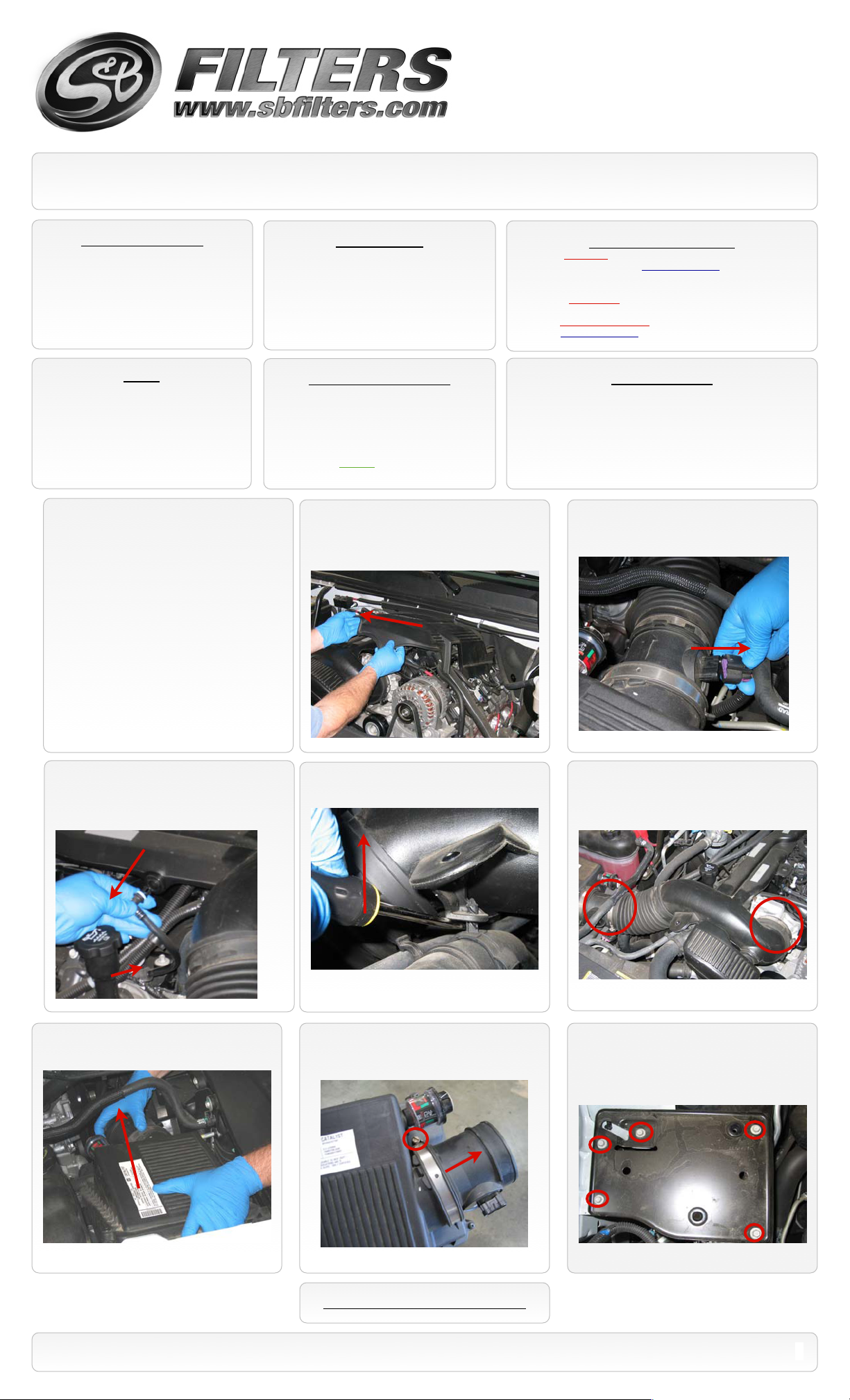
2. Pull up and out to remove the engine
cover from the vehicle.
Cleanable (KF-1035). If the enclosed filter is Red, it came pre-oiled
from the factory. Please visit www.sbfilters.com for exact oil
amount required after cleaning.
Disposable (KF-1035D). If the enclosed filter is White, it is a
disposable filter and should be discarded once it reaches capacity.
This filter (does not require oil). For more info on S&Bʼs disposable
filter, visit www.sbfilters.com.
Before You Start
S&B Filter Maintenance
Please read the entire product guide before proceeding.
•
Ensure all components listed on page 4 are present.
•
If you are missing any of the components, call our customer
•
support at (909) 947-0015.
Do not work on your vehicle while engine is hot.
•
Make sure the engine is turned off and the vehicle is in Park or
•
the Parking Brake is set.
3. Disconnect the electrical connection to
the MAF sensor at the OE air box.
4. Pull the crankcase vent line from the OE
intake tube and then from the engine along
with the rubber connector and remove it from
the vehicle.
7. Pull the OE air box towards the engine
and up to release it from the vehicle.
5.Carefully pry the hose router clamp from
the OE air intake tube.
8. Loosen the hose clamp on the OE air box
and remove the MAF sensor.
Note: Direction of arrow with regards to flow.
6. Loosen the hose clamp at the throttle
body and at the MAF sensor, remove the OE
intake tube from the engine.
9. Remove the OE air box tray from the
vehicle. Four of these bolts if long enough,
may be used to secure the S&B air box to the
vehicle. If not use the supplied M6 allen head
screws (K) and SS washers (R).
SEE EXPLODED VIEW ON PAGE 4
15461 Slover Ave., Fontana, CA 92337 - Phone: (909) 947-0015 - Fax: (909) 947-0603 - www.sbfilters.com
1
Page 2
Installation Instructions (continued)
P/N: 75-5042 / 75-5042D
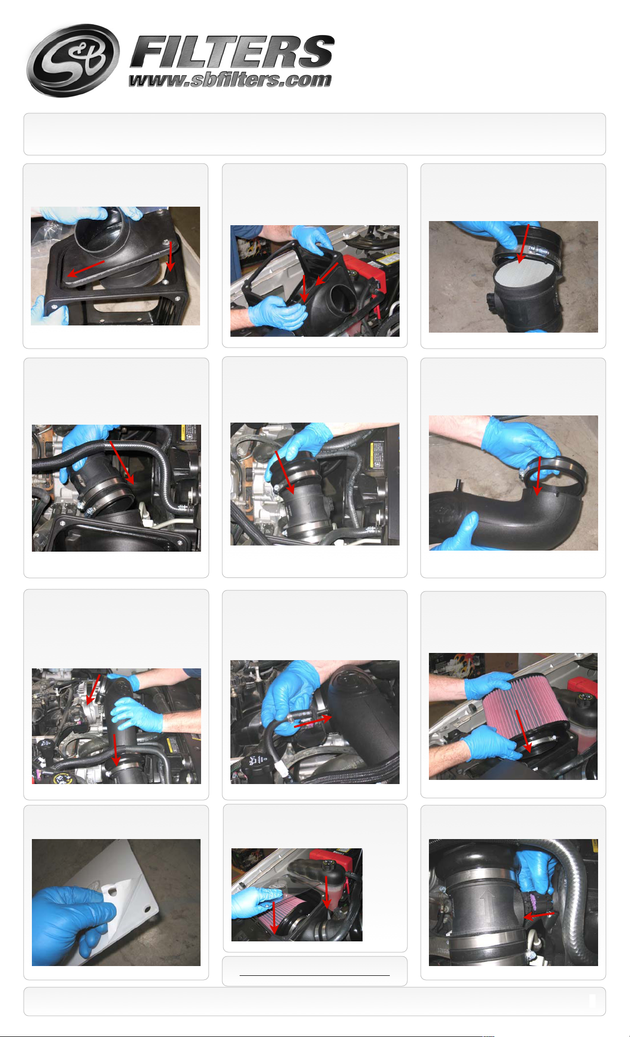
10. Attach the S&B Filter Adapter (I) to the
S&B Air box (G), secure using the 5/16 SS
Screws (H) provided.
13. Connect the MAF sensor assembly to
the S&B Filter Adapter ( I ) and secure using a
#60 Hose Clamp (J).
11. Place the S&B Air Box assembly into the
vehicle, align the 4 holes with the OE
mounting locations and secure using either
the OE bolts or the supplied M6 allen head
screws (K) and SS washers (R).
14. Slide the S&B Hump Adapter (L) over
the MAF sensor’s flange and secure using a #
60 Hose Clamp (J).
12. Slide the S&B Straight Adapter (F) over
the MAF sensor’s honey comb end, secure
using a # 60 Hose Clamp (J).
15. Slide the S&B Throttle Body Adapter (O)
over the S&B Tube (M) along with the # 72
Hose Clamp (N), do not tighten at this step.
16. Place another # 60 hose clamp (J) on
the Hump Adapter (L) then insert the small
end of the S&B Tube (M) into the S&B Hump
Adapter. Then position the other end of the
tube over the throttle body and firmly secure
the # 72 Hose Clamp (N), then secure the #
60 Hose Clamp (J) at the Hump Adapter.
19. Remove the protective covering from the
S&B Clear Lid (C).
17. Install the Crankcase Vent Hose (Q) onto
the S&B Intake Tube (M) vent port and then
onto the engine port where the OE line was
removed in step #4 . Secure with two # 4
Hose Clamps (P).
20. Place the Clear Lid (C) on the Air Box
(G) and secure using the 8/32 SS Screws (A)
and SS Washers (B).
18.Place the S&B Air Filter (D) into the S&B
Air Box (G), rotate the filter about a 1/4 turn
for clearance and slide onto the flange and
secure the # 80 Hose Clamp (E).
21. Reconnect the MAF sensor electrical
connection.
SEE EXPLODED VIEW ON PAGE 4
15461 Slover Ave., Fontana, CA 92337 - Phone: (909) 947-0015 - Fax: (909) 947-0603 - www.sbfilters.com
2
Page 3

EMISSIONS STANDARD
The California Air Resource Board (CARB) requires that an E.O. identification label be applied to the vehicle in order to pass a smog
check inspection when a Performance Intake Kit has been installed. You must place the E.O. label provided on or near the intake kit
after installation so that a smog check technician can easily verify the E.O. number. As of April 2009, S&B has never had a product
where CARB denied an exemption request; however, the exemption process with CARB can take as long as 18 months. Check the
status of the exemption process by looking up a specific part number at www.sbfilters.com. The CARB Exemption number and/or
status is listed under the Product Details section for each part number. If the status shows as “Pending,” CARB has yet to issue an
exemption. Products that have not been issued an EO number are street legal in most states, but may not be used on emission
controlled vehicles in the state of California and are for off road use only. If you purchased your kit from S&B Filters directly, we will
automatically mail you your Exemption Sticker when it is issued to us. If you purchased your kit from an authorized S&B Filters Dealer,
log onto our web site and register to receive your Exemption Sticker.
Installation Instructions (continued)
P/N: 75-5042 / 75-5042D
22. Install the engine cover. 23. Reconnect the negative battery cable. 24. Inspect your installation, make sure kit
is properly positioned and all fasteners are
tight.
25. Affix the C.A.R.B. exemption sticker in
plain sight under the hood.
PRECISION II
FILTER CLEANING & OILING
Order online today at www.sbfilters.com or
through your local S&B distributor.
Part #: 88-0008
RELATED ITEMS FOR YOUR
PURCHASE
Replacement Air Filter (Oiled)
•
(S&B P/N: KF-1035)
Replacement Air Filter (Dry)
•
(S&B P/N: KF-1035D)
Air Filter Wrap (S&B P/N: WF-1023)
•
Performance Testing
Engage parking brake and start your engine. Listen for abnormal noises. If an air leak is detected, re-inspect hoses and connections as they may need to be repositioned and
•
tightened.
S&B FILTERS recommends that you keep your OE intake system in the event it is required in the future.
•
In order to maintain your warranty, all connections and components must be checked periodically for alignment and for proper tension on all connections. Failure to do so
•
may void your warranty.
Use only S&B FILTERS cleaning and oil products to service your filter. Using any other brand oil and or cleaners on your S&B air filter may void your warranty.
•
Warning!
If your vehicle has a Vehicle Emission Control Information decal affixed to the factory airbox, a new
replacement label must be obtained and installed in a readily visible position in the engine compartment in
order to remain CARB compliant. Failure to do so will prevent the vehicle from passing a smog check.
Replacement labels can be ordered from your local dealership. Regulations state that the VECI label shall
not be affixed to any equipment which is easily detached from the vehicle. Label placement, under the hood
on a painted surface is recommended.
15461 Slover Ave., Fontana, CA 92337 - Phone: (909) 947-0015 - Fax: (909) 947-0603 - www.sbfilters.com
SEE EXPLODED VIEW ON PAGE 4
3
Page 4

ITEM
QTY.
DESCRIPTION
P/NA4
10-24 SS Screws
AI1287-00
B410-24 SS Washers
AI1272-00
C1Clear Lid
AI1371-00
D1S&B Air Filter
KF1035E1
#80 Hose Clamp
AG1010-00
F1Straight Adapter
AI1129-00
G1Air Box
AL1080B-00
H25/16” - 18 SS Screw
AI1297-00
I1Air Box Adapter
AL1084A-00
J4#60 Hose Clamp
AG1008-00
K4M6 Allen Head Screw
AI1366-00
L1Hump Adapter
AI1321-00
M1Induction Tube
AL1089-00
N1#72 Hose Clamp
AG1009-00
ITEM
QTY.
DESCRIPTION
P/N
O1Throttle Body Adapter
AI1097-00
P2#4 Hose Clamp
AG1021-00
Q1Hose 3/8 x 13”
AI1037-04
R43/8 x 1” S.S. Washer
AI1341-00
EXPLODED VIEW
P/N: 75-5042 / 75-5042D
15461 Slover Ave., Fontana, CA 92337 - Phone: (909) 947-0015 - Fax: (909) 947-0603 - www.sbfilters.com
AM0129-00 Rev.D 10/01/13
4
 Loading...