

Page 1
INSTALLATION INSTRUCTIONS
P/N: 75-5032 / 75-5032D
!"#$%&&%$!'"(!"#$)*+$!'"#
!"#$%&&%$!'"(!"#$)*+$!'"#((
EFG!+H.!'*(*$2I!
I$$2(I$$'!3A?J!
!
3(I*$K!3(2*$K!3(&*$K!3(**$K!!
/L@M?8;AN!
17$O!+A6>?!E=?AP>!Q;>8><!
!
-!!!!./0!123!450!6/0!789/:;8<!=/09!098!!
65;;5=/4>!!"#$%&'%($#)*'%#+)/4<02;;8?@!
,-./)01"#)
23+#-&)4--.)
53%6-)789%'.$)
:;#$%<--=$%)789%'.$+)
RBSA?=TN=!.A=>U!!"#$"%#&'()#*+#,-'#
"./.#&'0,&12,1*+#3453'#*ʁ,#5+,1(#,-'#
740-#(13-,#10#,&133'&'7#8'9*&'#)*5##
0'&:12'#)*5&#;<=#41[(,'&.#
!
!
VWX!+4DWE!OREW!VWX!+4DWE!OREW!!
>## ?@A#B+,4C'#%58'#D#E1(,'&#F74G,'&# >## ?EA#H5IG#F74G,'&#
>## ?;A#;-*&,#%58'# J# ?KA#L#MN#H*0'#O(4IG#
>## ?PA#F1&#=*Q# R# ?FA#>SDJN#;;#;2&'6#
>## ?TA#O('4&#P17# U## ?=A#V588'	**,'7#640-'&#
J# ?HA#RD>MW>X#=*(,# ># ?/A#YFE#K40C',#
J# ?BA#RD>M#Z40-'&# J# ?OA#XD[J#Q#UD>M#;2&'60#
>## ?"A#;<=##F1&#E1(,'&# ># ?\A## F1&#=*Q#K&*II',#
[## ?!A#LUJ#H*0'#O(4IG# ># ?]A#Y FE#;'+0*&#=(*2C#"99#T(4,'#
###>## ?YA#E'+7'&#Z40-'&# ># ?VA#B+,4C'#%58'#K&*II',#
###>### ?$A#P*2C#$5,# ># ?%A#;,&413-,#F74G,'&#
## ##
W--OE!D/VYRD/Q!
X^#>SII#Z&'+2-#*&#;*2C',#
>DJ_#Z&'+2-#
E(4,#;2&'67&1:'&#*&##
RD>M#$5,#7&1:'&#
T-1((1G#;2&'67&1:'&#
%WJS#;'25&1,)#%*&Q# 6&'+2-#
?05GG(1'7#61,-#C1,A#
RDX_#!&1((#=1,#4+7#!&1((#
`*5&#;<=#F1&#E1(,'
##
942,*&)#*1('7#4+7#&'47)#
#,*#50'.#F1&#E1(,'&#TD$##
\EW>SN[#61((#&'a51&'#bS3#
*9#*1(#6-'+#0'&:12'7.#
)7!!!!!Z1,-#,-'#13+1,1*+#061,2-'7#*99^##
7102*++'2,#,-'#+'34,1:'#84,,'&)#248('0.#
#
*!"4%7!B9#)*5#-4:'#,-'#"/#[W6A!+;>@>\!1+,4C'#
,58'^#(**0'+#,-'#-*0'#2(4IG#4,#,-'#8'((*60.#
#
#
17!!T5((#5G#4+7#*5,#*+#,-'#"/#41*Q#4+7#
,58'#400'I8()#,*#&'I*:'#1,#9&*I#,-'#:'-12('.#
%-'#"/#3&*II',0#0-*5(7#&'I41+#1+#,-'#,&4).#
!"#$%&&%$!'"(!"#$)*+$!'"#
!"#$%&&%$!'"(!"#$)*+$!'"#((
EFG!+H.!'*(*$2I!
I$$2(I$$'!3A?J!
!
3(I*$K!3(2*$K!3(&*$K!3(**$K!!
/L@M?8;AN!
17$O!+A6>?!E=?AP>!Q;>8><!
!
-!!!!./0!123!450!6/0!789/:;8<!=/09!098!!
65;;5=/4>!!"#$%&'%($#)*'%#+)/4<02;;8?@!
,-./)01"#)
23+#-&)4--.)
53%6-)789%'.$)
:;#$%<--=$%)789%'.$+)
RBSA?=TN=!.A=>U!!"#$"%#&'()#*+#,-'#
"./.#&'0,&12,1*+#3453'#*ʁ,#5+,1(#,-'#
740-#(13-,#10#,&133'&'7#8'9*&'#)*5##
0'&:12'#)*5&#;<=#41[(,'&.#
!
!
VWX!+4DWE!OREW!VWX!+4DWE!OREW!!
>## ?@A#B+,4C'#%58'#D#E1(,'&#F74G,'&# >## ?EA#H5IG#F74G,'&#
>## ?;A#;-*&,#%58'# J# ?KA#L#MN#H*0'#O(4IG#
>## ?PA#F1&#=*Q# R# ?FA#>SDJN#;;#;2&'6#
>## ?TA#O('4&#P17# U## ?=A#V588'	**,'7#640-'&#
J# ?HA#RD>MW>X#=*(,# ># ?/A#YFE#K40C',#
J# ?BA#RD>M#Z40-'&# J# ?OA#XD[J#Q#UD>M#;2&'60#
>## ?"A#;<=##F1&#E1(,'&# ># ?\A##F1&#=*Q#K&*II',#
[## ?!A#LUJ#H*0'#O(4IG# ># ?]A#YFE#;'+0*&#=(*2C#"99#T(4,'#
###>## ?YA#E'+7'&#Z40-'&# ># ?VA#B+,4C'#%58'#K&*II',#
###>### ?$A#P*2C#$5,# ># ?%A#;,&413-,#F74G,'&#
## ##
W--OE!D/VYRD/Q!
X^#>SII#Z&'+2-#*&#;*2C',#
>DJ_#Z&'+2-#
E(4,#;2&'67&1:'&#*&##
RD>M#$5,#7&1:'&#
T-1((1G#;2&'67&1:'&#
%WJS#;'25&1,)#%*&Q# 6&'+2-#
?05GG(1'7#61,-#C1,A#
RDX_#!&1((#=1,#4+7#!&1((#
`*5&#;<=#F1&#E1(,'
##
942,*&)#*1('7#4+7#&'47)#
#,*#50'.#F1&#E1(,'&#TD$##
\EW>SN[#61((#&'a51&'#bS3#
*9#*1(#6-'+#0'&:12'7.#
)7!!!!!Z1,-#,-'#13+1,1*+#061,2-'7#*99^##
7102*++'2,#,-'#+'34,1:'#84,,'&)#248('0.#
#
I7!!!!102*++'2,#,-'#&4714,*&#*:'&9(*6#-*0'#
#9&*I#,-'#&'0'&:*1&.##
#cY8>!@TM=;AN!40#,-'#0)0,'I#I4)#8'#5+7'&##
G&'005&'#4+7#,-'#2**(4+,#I4)#8'#-*,.#
27!!R:!/ZM;SS>JU!!102*++'2,#,-'#'('2,&124(#
2*++'2,1*+#4,#,-'#"/#&'0,&12,1*+#3453'.#
#
*!"4%7!B9#)*5#-4:'#,-'#"/#[W6A!+;>@>\!1+,4C'#
,58'^#(**0'+#,-'#-*0'#2(4IG#4,#,-'#8'((*60.#
#
#
17!!T5((#5G#4+7#*5,#*+#,-'#"/#41*Q#4+7#
,58'#400'I8()#,*#&'I*:'#1,#9&*I#,-'#:'-12('.#
%-'#"/#3&*II',0#0-*5(7#&'I41+#1+#,-'#,&4).#
'7!B+0'&,#,-'#;<=#K&*II',#?\A#1+,*#,-'#*:4(#
I*5+,1+3#-*('#1+#,-'#;<=#F1&#=*Q#?PA.#
#
*!"G%7!B9#)*5#-4:'#,-'#"/#[-N>!+;>@>\!1+,4C'#
,58'^#(**0'+#,-'#-*0'#2(4IG#4,#,-'#,5&8*#9(4+3'.#
F+7#G5((#,-'#"/#8&'4,-'&#,58'#9&*I#,-'#:4(:'#
2*:'&.#
#
#
![W6A!+;>@>\!-/!;N=TP>!=M9>!
]7!!V'I*:'#,-'#"/#&'0,&12,1*+#3453'#9&*I#
,-'#"/#1+,4C'^#,-'+#&'I*:'#,-'#3&*II',#
4+7#1+0'&,#1,#1+,*#,-'#&*5+7#-*('#1+#,-'#;<=#
F1&#=*Q#?PA#
#
Vehicle Application
Year: 2003-07
Make: FORD
Model: F-250 - F-550, EXCURSION
Engine: 6.0L DIESEL
Notes
Kit may not fit with the following:
Aftermarket Parts installed
•
Body Lift or Lowering Kit
•
Custom Hood
•
Intercooler or Turbo upgrades
•
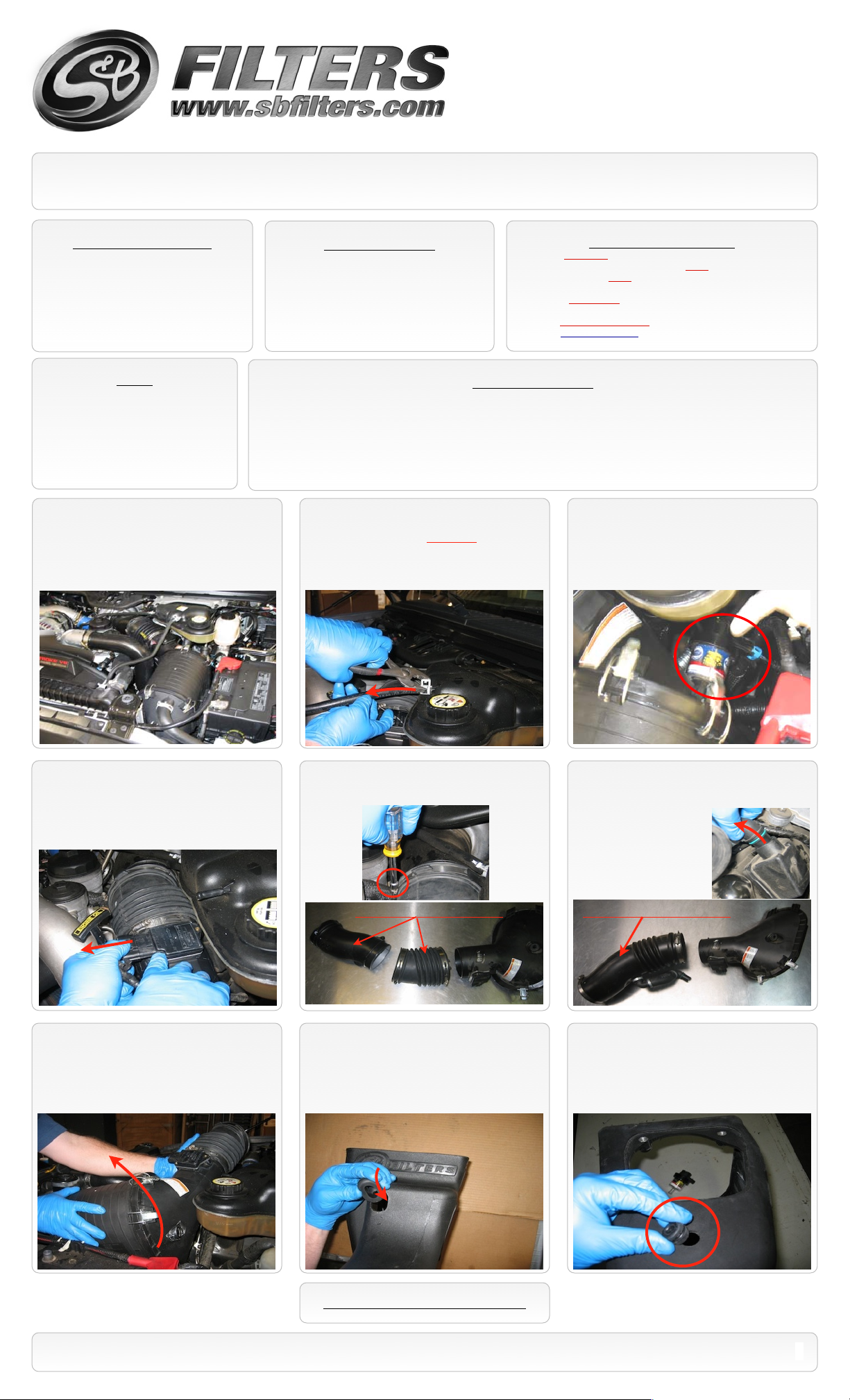
1. With the ignition switched off and the
parking brake set, disconnect the negative
battery cables.
4. Depending on your vehicle year,
disconnect either the MAF sensor or the
Temp. sensor electrical connection on the OE
intake tube.
Tools Required
8mm & 10mm Wrench & Socket
•
1/2” Wrench & Socket
•
Phillips Screwdriver
•
5/16” Nut Driver or Flat Blade Screwdriver
•
Drill and 5/8” Drill Bit
•
Cleanable (KF-1054). If the enclosed filter is Red, it came pre-oiled
from the factory. When serviced, apply (75g) of S&B oil to the main
body of the filter and (23g) to the Power Stack (Top).
Disposable (KF-1054D). If the enclosed filter is White, it is a
disposable filter and should be discarded once it reaches capacity.
This filter (does not require oil). For more info on S&Bʼs disposable
filter, visit www.sbfilters.com.
S&B Filter Maintanence
Before You Start
Please read the entire product guide before proceeding.
•
Ensure all components listed on page 5 are present.
•
If you are missing any of the components, call our customer support at (909) 947-0015.
•
Do not attempt to work on your vehicle while engine is hot.
•
Make sure the engine is turned off and the vehicle is in Park or the Parking Brake is set.
•
2. Disconnect the radiator overflow hose
from the reservoir. Use CAUTION as the
system may be under pressure and the
coolant may be hot.
5 (A). If you have the OE “Two Piece”
intake tube, loosen the hose clamp at the
bellows.
3. If Equipped: Disconnect the electrical
connection at the OE restriction gauge
located at the back of the air box.
5 (B). If you have the OE “One Piece”
intake tube, loosen the hose clamp at the
turbo flange. Then Pull
the OE breather tube
from the valve cover.
6. Pull up and out on the OE air box and
tube assembly to remove it from the vehicle.
The OE grommets should remain in the tray.
“Two Piece” OE Intake Tube “One Piece” OE Intake Tube
7. Insert the Grommet (K) into the oval
mounting hole in the front of the Air Box (L).
8. Remove the OE restriction gauge from
the OE intake, then remove the grommet and
insert it into the round hole in the back of the
Air Box (L).
SEE EXPLODED VIEW ON PAGE 5
787 S. Wanamaker, Ontario, CA 91761 - Phone: (909) 947-0015 - Fax: (909) 947-0603 - www.sbfilters.com
1
Page 2
INSTALLATION INSTRUCTIONS (continued)
P/N: 75-5032 / 75-5032D
9. Prior to installing the Air Box (L), you may
need to rotate the factory intercooler clamp
that is located just below the OE air box to
add clearance for the new one.
11. Carefully place the Air Filter (O) into the
Air Box (L).
10 (A). Grease the prongs on the bottom of the
Air Box (L) and place the box in the vehicle. Tilt
towards the front, align mounting hole over the stud
in the core support. Then push down on the Air Box
to seat the prongs into the OE grommets. Use
Washer (M) and Lock Nut (N) to secure the air box.
NOTE: If you have the OE “Two
Piece” intake tube pictured in step #5(A)
you will skip steps #12 thru #16, resume
at the note prior to step #17.
10 (B). NOTE: If you do not seat the air
box properly in the OE saddle and grommets,
there will be an interference between the air
box and the hood when the hood is closed.
Check for clearances before you proceed.
12. Install the Straight Adapter (T) to the
turbo flange, secure using a #64 Hose Clamp
(G).
13. Spread the OE clamp open and remove
the breather tube assembly from the OE
intake tube.
Loosen Clamp
16. Insert the OE breather tube assembly
into the valve cover.
14. Install the large Grommet (R) into the
Short Tube (S) followed by the 90 degree OE
breather tube fitting.
15. Insert the Short Tube (S) assembly into
the Straight Adapter (T), align the breather
tube then secure using a #64 hose clamp (G).
Grommet
Temp. Sensor NOTE: If your vehicle uses a Temp. Sensor in place of a MAF Sensor: Use
the supplied MAF Block Off Plate (Q), 8/32 Screws (C) and Washers (B) and Gasket (E) in place of
the MAF sensor. You will also need to drill a 5/8” hole at the drill point on the tube, located opposite
of the MAF port. Remove the OE Temp. Sensor and OE grommet and insert the grommet into the
5/8” hole you drilled in the Intake Tube Adapter (J) followed by the Temp Sensor. Continue with step
#19.
Drill 5/8” hole here for
Temp. Sensor only.
* Clean tube of any debris
before installation.
SEE EXPLODED VIEW ON PAGE 5
787 S. Wanamaker, Ontario, CA 91761 - Phone: (909) 947-0015 - Fax: (909) 947-0603 - www.sbfilters.com
2
Page 3

INSTALLATION INSTRUCTIONS (continued)
P/N: 75-5032 / 75-5032D
17. Use the supplied T-20 Torx tool and
remove the MAF sensor from the OE intake.
20. Place the Intake Tube Adapter (J) in the
vehicle as shown, then rotate the tube so the
MAF or Block Off Plate is facing up.
18. Use the supplied MAF Gasket (E) and
8/32 screws (C) to attach the MAF sensor to
the Intake Tube Adapter (J), Do not over
tighten!
21. Attach the Intake Tube Adapter (J) to the
Air Box (L). Clip the adapter to the box and
insert the tube into the Air Filter (O)
simultaneously.
19. Slip the Hump Adapter (F) along with
two #72 hose clamps (D) over the Intake
Tube Adapter (J) until nearly flush with the
end.
22. Secure the adapter to the box using the
5/16 washers (I) and Bolts (H).
23. Secure the Air Filter (O) to the Intake
Tube Adapter (J) using the #72 Hose Clamp
(D).
26. Insert the OE restriction gauge into the
Air Box (L), then reconnect to the harness.
NOTE: DO NOT rely on the OE restriction
gauge or wait until the dash light is triggered
before you service your S&B air filter.
24. Slide the Hump Adapter (F) over the
turbo inlet tube, center over the gap and
secure both #72 Hose clamps (D).
27. Reconnect the radiator overflow tube to
the reservoir.
25. Reconnect the electrical connector to
either the MAF sensor located on top of the
tube or Temp. Sensor located underneath.
28. Remove the protective film from the
Clear Lid (P) and place it on the Air Box (L),
secure using the 10/24 SS Screws (A) and
SS Sealing Washers (B).
SEE EXPLODED VIEW ON PAGE 5
787 S. Wanamaker, Ontario, CA 91761 - Phone: (909) 947-0015 - Fax: (909) 947-0603 - www.sbfilters.com
3
Page 4

EMISSIONS STANDARD
The California Air Resource Board (CARB) requires that an E.O. identification label be applied to the vehicle in order to pass a smog
check inspection when a Performance Intake Kit has been installed. You must place the E.O. label provided on or near the intake kit
after installation so that a smog check technician can easily verify the E.O. number. As of April 2009, S&B has never had a product
where CARB denied an exemption request; however, the exemption process with CARB can take as long as 18 months. Check the
status of the exemption process by looking up a specific part number at www.sbfilters.com. The CARB Exemption number and/or
status is listed under the Product Details section for each part number. If the status shows as “Pending,” CARB has yet to issue an
exemption. Products that have not been issued an EO number are street legal in most states, but may not be used on emission
controlled vehicles in the state of California and are for off road use only. If you purchased your kit from S&B Filters directly, we will
automatically mail you your Exemption Sticker when it is issued to us. If you purchased your kit from an authorized S&B Filters Dealer,
log onto our web site and register to receive your Exemption Sticker.
INSTALLATION INSTRUCTIONS
P/N: 75-5032 / 75-5032D
29. Reconnect the battery cables. Inspect
your installation, make sure the kit is properly
positioned and all fasteners are secure.
Precision II
Filter Cleaning & Oiling
Engage parking brake and start your engine. Listen for abnormal noises. If an air leak is detected, re-
•
inspect hoses and connections as they may need to be repositioned and tightened.
S&B FILTERS recommends that you keep your OE intake system in the event it is required in the future.
•
In order to maintain your warranty, all connections and components must be checked periodically for
•
alignment and for proper tension on all connections. Failure to do so may void your warranty.
Use only S&B FILTERS cleaning and oil products to service your filter. Using any other brand oil and or
•
cleaners on your S&B air filter may void your warranty. Visit sbfilters.com for complete warranty
information.
RELATED ITEMS FOR YOUR
PURCHASE
Replacement Air Filter (Oiled)
PERFORMANCE TESTING
•
•
(S&B P/N: KF-1054D)
•
(S&B P/N: KF-1054)
Replacement Air Filter (Dry)
Air Filter Wrap (S&B P/N: WF-1021)
Order online today at www.sbfilters.com or
through your local S&B distributor.
Part #: 88-0008
SEE EXPLODED VIEW ON PAGE 5
787 S. Wanamaker, Ontario, CA 91761 - Phone: (909) 947-0015 - Fax: (909) 947-0603 - www.sbfilters.com
4
Page 5

ITEM
QTY.
DESCRIPTION
P/NA4
S.S. Screw, 10-24 x 1/2”
AI1287-00
B6S.S. Sealing Washer, 10-24
AI1272-00
C2Screw, 8-32 x 7/16”
AI1192-00
D3Hose Clamp #72
AG1009-00
E1MAF Gasket
AI1357-00
F1Adapter, Hump, 4.10”ID
AI1333S-00
G2Hose Clamp #64
AG1018-00
H2Screw, 5/16-18 x 1.0”
AI1199-00
I2Washer, Flat, 5/16”
AI1093-00
J1Intake Adapter Tube
AL1081A-00
K1Grommet, Air Box
AI1368-00
L1Air Box
AL1090B-00
M1Washer, Fender, 1/4”ID
AI1075-00
N1Nut, Lock, M6-1.0
AI1090-00
ITEM
QTY.
DESCRIPTION
P/NO1
S&B Air Filter
KF-1054
P1Clear Lid
AI1384-00
Q1MAF Block Off Plate
AI1367-00
R1Grommet, Intake Tube
AI1386-00
S1Short Tube
AL1081-00
T1Adapter, Straight, 4.10”ID
AI1029S-00
EXPLODED VIEW
AM0125-00 Rev.K 12/20/12
P/N: 75-5032 / 75-5032D
Warranty
Visit www.sbfilters.com for complete warranty information.
787 S. Wanamaker, Ontario, CA 91761 - Phone: (909) 947-0015 - Fax: (909) 947-0603 - www.sbfilters.com
5
 Loading...