

Page 1

INSTALLATION INSTRUCTIONS
INSTALLATION INSTRUCTIONS
S&B P/N 75-5020
2006 Ford F-150 4.6L
∗ Kit may not fit vehicles with the
following Aftermarket Parts installed.
∗ Body Lift
∗ Custom Hood
∗ Throttle Body Upgrade
∗ Throttle Body Spacer
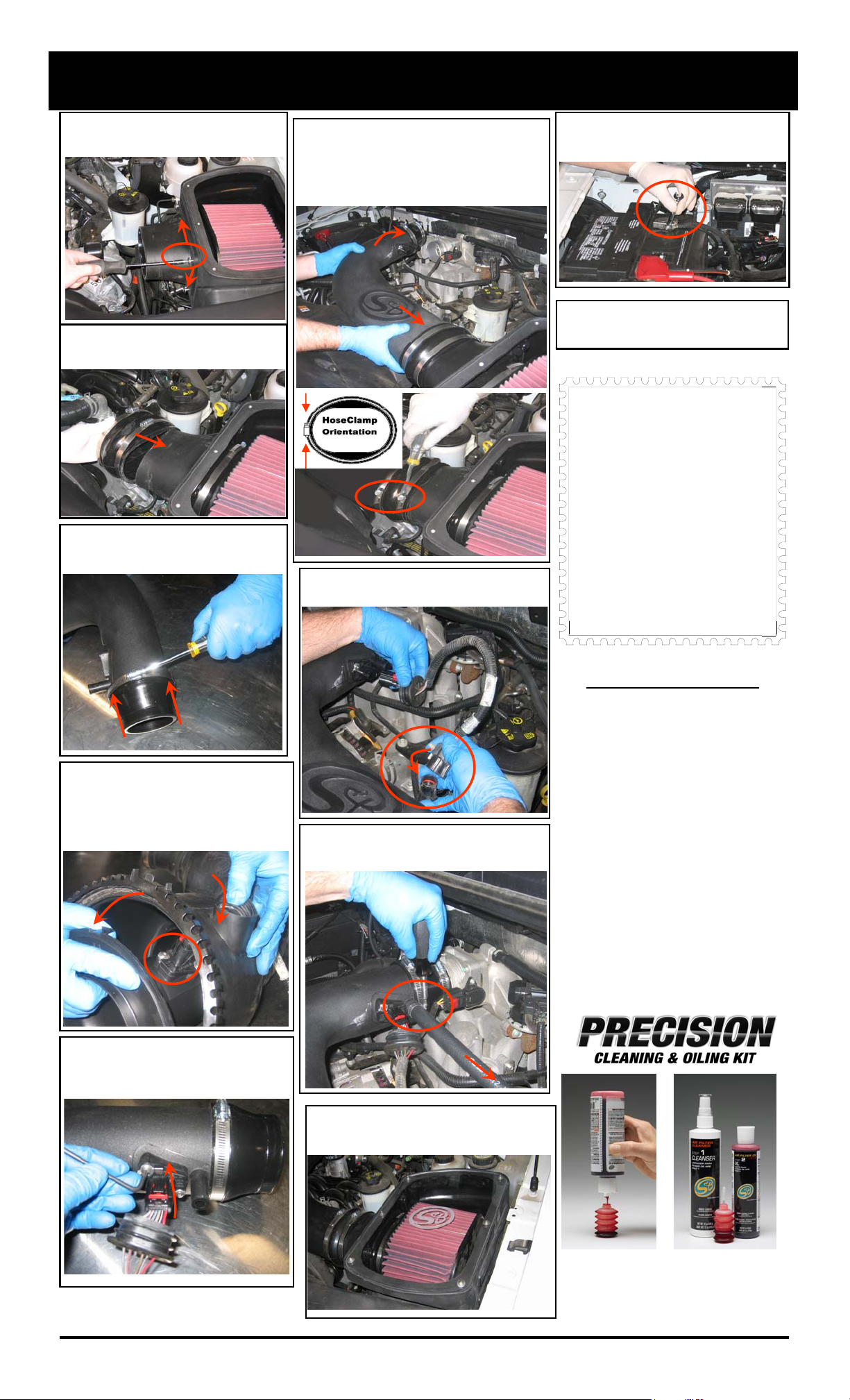
1. With the ignition switched off, disconnect
the negative battery cable, use an 8mm
wrench or socket.
QTY PARTS LIST QTY PARTS LIST
1 (C) Intake Tube 1 (P) 3”-3.5” step adapter
1 (O) Air Box 1 (F) # 56 Hose Clamp
1 (R) Clear Lid 1 (T) #104 Hose Clamp
1 (E) 3.725”x2.938” step adapter 2 (G) # 88 Hose Clamp
4 (I) 5/16-18 SS Screw 1 (D) # 60 Hose Clamp
4 (M) 5/16 Fender Washer 2 (B) # 8 Hose Clamp
2 (N) 5/16-18 Bolt 1 (V) # 52 Hose Clamp
2 (K) 5/16-18 Lock Nut 1 (Q) S&B Air Filter
2 (L) Rubber Spacer 1 (A) 5/8“x25” Hose
1 (J) Filter Adapter 6 (S) 10/24 SS Screws
1 (H) Oval Hump Adapter 6 (U) 10/24 SS Concave Washer
5. Remove the OE rubber grommets from the
inner fender tray (drivers side) and relocate
the wire loom closer to the fender.
7. Install the S&B air box (O) and secure
using the 5/16 bolts (N), fender washers (M),
rubber spacers (L) and lock nuts (K)
provided. See diagram below.
TOOLS REQUIRED
1/2” Wrench & Socket
Ratchet
5/16” Nut Driver or
Flat Blade Screwdriver
T-20 Torx wrench
(supplied with kit)
Phillips head screwdriver
Your S&B Air Filter is
factory oiled and ready
to use. Air Filter P/N
KF-1031 will require 71g
of oil for main body and
17g of oil for the top
when serviced.
2. Disconnect the crank case vent line from
the driver side valve cover to the OE intake
tube and remove from vehicle.
3. Disconnect the electrical connection for
the MAF sensor at the pig tail coming from
the OE intake tube.
6. Install the 3” to 3.5” adapter (P) to the fender
snout on the S&B air box (O), push on as far as
it will go, it may feel loose but will secure with
#56 hose clamp (F).
4. Loosen the hose clamp at the throttle body
pull out and then towards the left, pulling the
OE intake assembly out of the drivers side
inner fender.
8/21/2008
REV-A
(909) 947-0015 PHONE • (909) 947-0603 FAX
www.sbfilters.com
8. Place the S&B air filter (Q) inside S&B air
box (O). Offset flange is toward the front of
the vehicle. Snap S&B filter adapter (J) into
S&B air filter (Q) secure with #104 hose
clamp (T).
(OVER)
Page 2
INSTALLATION INSTRUCTIONS (continued)
9. Secure the S&B flange adapter (J) to the
S&B air box (O) with the four 5/16 SS Phillips
head screws (I) provided.
10. Place the Oval Hump adapter (H) over
the filter adapter (J), do not tighten hose
clamps at this step.
11. Install the 3.75”-2.45” adapter (E) to the
S&B tube (C) as shown, secure with # 60
hose clamp (D).
14. Install the S&B tube (C) into the Oval hump
adapter (H) then onto the throttle body. Center
the Oval hump adapter (H) over gap between the
tube ends and secure with #88 hose clamps
(G) , then secure # 52 hose clamp (V) at throttle
body. Note: Position clamps as shown below.
2nd
1st
15. Reconnect MAF sensor electrical connection.
Check that both connectors are fully engaged.
18. Reconnect the battery. Inspect your
installation, make sure kit is properly
positioned and all fasteners are secure.
19. Affix the C.A.R.B. exemption sticker in
plain sight under the hood near the intake
system.
Smog Certification Note:
The California Air Resource Board
(CARB) requires that an E.O.
identification label be applied to the
vehicle in order to pass a smog
check inspection when a High
Performance Intake Kit has been
installed.
You must place the E.O. label
provided on or near the intake kit
after installation so that a smog
check technician can easily verify
the E.O. number.
12. Remove the MAF sensor from the OE air
box; pull the rubber plug out then turn it sideways and push it through the hole, separate
the housing and using the #T-20 Torx wrench
supplied remove the MAF sensor.
Note: Direction of sensor related to air flow.
13. Install the MAF sensor into the S&B tube
(C). Secure with the OE screws, tighten
evenly and do not over tighten!
Note: Direction of sensor related to air flow.
1.
16. Install the S&B 5/8” crankcase vent hose (A)
from the valve cover to the S&B Intake tube (C),
secure both ends with #8 hose clamps (B).
PERFORMANCE TESTING
∗ Engage parking brake and start your
engine. Listen for abnormal noises. If an
air leak is detected, re-inspect hoses and
connections as they may need to be repositioned and tightened.
∗ S&B FILTERS RECOMMENDS THAT
YOU KEEP YOUR OEM INTAKE SYSTEM IN THE EVENT IT IS REQURIED IN
THE FUTURE.
∗ In order to maintain your warranty, all
connections and components must be
checked periodically for alignment and
for proper tension on all connections.
Failure to do so will void your warranty.
∗ Use only S&B Filter cleaning and oil prod-
ucts to service your filter. Using any other
brand oil and or cleaners may void your
warra
nty.
8/21/2008
REV-A
17. Install the S&B clear lid (R), secure with
10/24 screws (S) and sealing washers (U).
Do not over tighten.
Part No. 88-0005
Order online today at www.sbfilters.com
or though your local S&B Distributor
(909) 947-0015 Phone • (909) 947-0603 Fax
www.sbfilters.com
Page 3

Kit 75-5020
S&B Intake
8/21/2008
REV-A
 Loading...