

Page 1
INSTALLATION INSTRUCTIONS
INSTALLATION INSTRUCTIONS
S&B P/N 75-5003
2005-2006
FORD Mustang GT
4.6L V8
manufactured prior to April of 2005)
Non hydrocarbon absorber equipped
models only.
For 2005 models not equipped with the HC absorber,
permitted Ford intake part numbers 6R33-9C662-BG
(manual trans) or 6R33-9C662-CG (auto trans).
To verify: Locate the label on the front facing vertical
wall of the lower part of the stock air box.
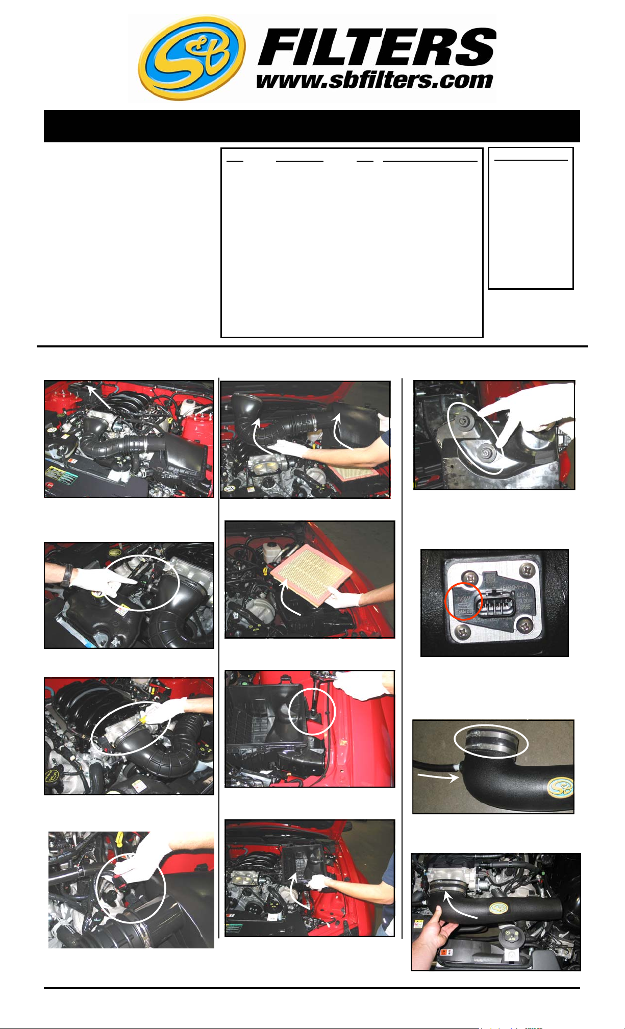
1. Turn off the ignition and disconnect the
negative battery terminal.
(excluding models
QTY PARTS LIST QTY PARTS LIST (continued)
1 1/2” x 16” Hose 1 #10-24 Pan Head Screws
1 4.5” - 2” Adapter 1 #10-24 Nylock Nuts
1 Intake Tube 2 #10 Washers
1 Air Box 1 Angled Bracket
1 Clear Lid 1 1/2” x 1/4” NPT Hose Barb
1 Air Filter 2 5/16” - 18 Acorn Nuts
2 #72 Hose Clamps 2 5/16” Jam Nuts
2 #8 Rubber Washers 2 5/16” Bolts
1 MAF Sensor Mounting Plate 4 Sealing Washers
1 MAF Sensor Mounting Gasket 4 SS Pan Head Screws
2 #10-32 Pan Head Screws 1 #8 Hose Clamp
2 #8-32 Pan Head Screws
5. Unlatch the air box lid and remove the intake
tube and lid assembly.
9. Remove the grommets from the OE air box.
These will be used to secure the S&B air box.
TOOLS REQUIRED
10 mm Wrench &
Socket
1/2” Wrench & Socket
Flat Head Screwdriver
Phillips Screw Driver
T-20 Torx wrench
(supplied)
2. Disconnect the crank case vent line from the
intake tube and the valve cover, remove it from
the vehicle.
3. Loosen the hose clamp that attaches the
intake tube to the throttle body.
4. Disconnect the electrical connection from the
MAF sensor
.
6. Remove the OEM panel filter from the air box.
7. Loosen the bolt that secures the air box using
a 10mm socket and ratchet.
8. Pull up and remove the air box from the
vehicle.
10. Use the # 8 screws and attach the MAF to the
sensor plate with rubber washers between MAF
and plate. Then attach plate to tube. Point the
arrow on the MAF sensor towards the engine.
11. Carefully install the NPT hose barb into the
intake tube making sure not to cross thread, then
install the 1/2” breather hose onto the hose barb.
Next install the 4” round adapter and hose
clamps to the throttle body end of the tube.
12. Install the S&B Intake Tube on to the throttle
body.
2/1/2010
REV-D
(909) 947
-0015 PHONE • (909) 947-0603 FAX
www.sbfilters.com
(OVER)
Page 2
INSTALLATION INSTRUCTIONS (continued)
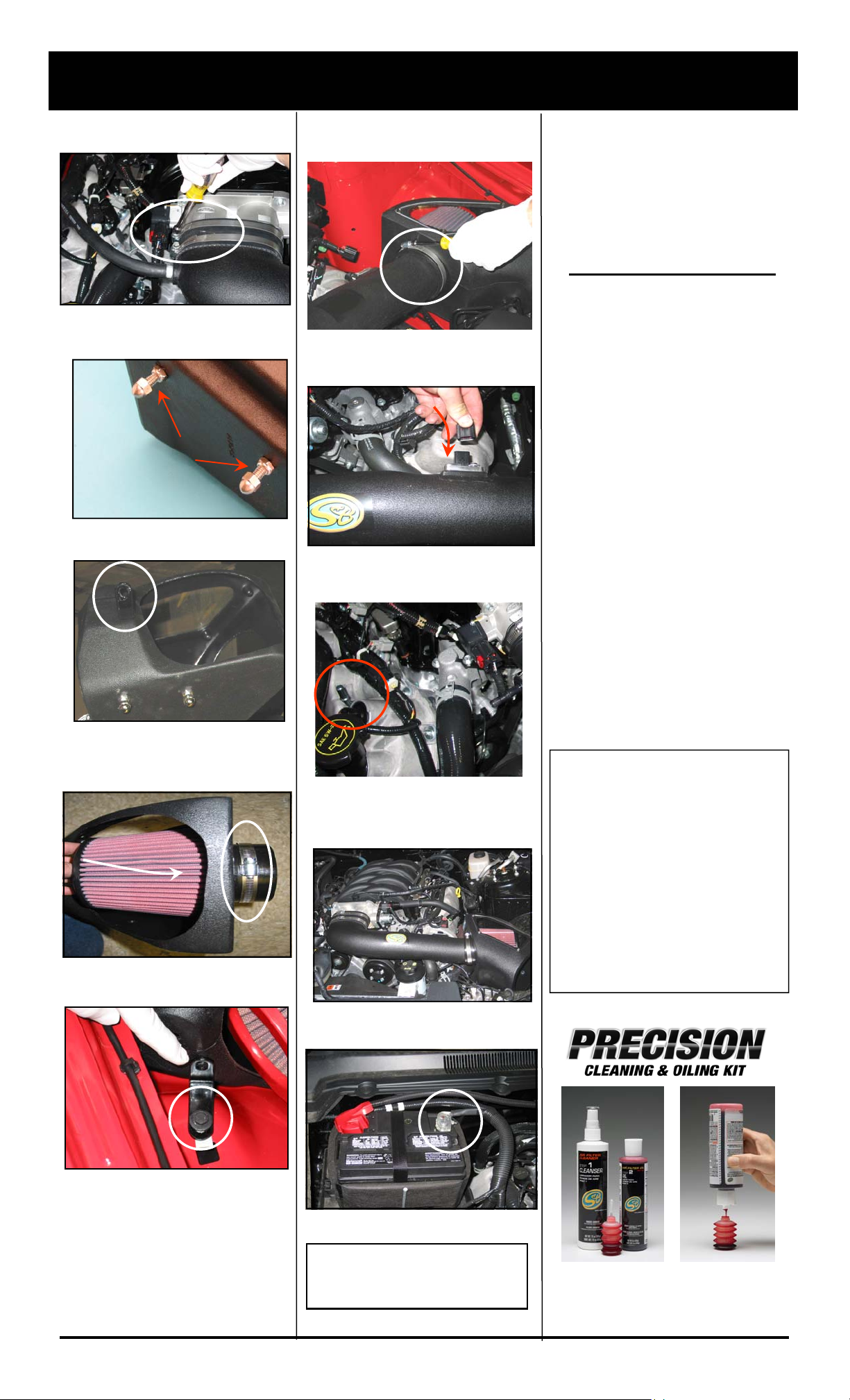
13. Tighten the hose clamp and secure the
tube to the throttle Body.
14. Assemble the air box using the 5/16” hardware. Take the stock grommets from step #9 put
them back in the fender before installing the box.
15. Install the “L” bracket short side to the air
box, leave loose for adjustment.
18. Secure the air filter to the tube by tightening
the hose clamp, then secure the air box “L”
bracket.
19. Reconnect the MAF sensor electrical
connection.
20. Connect the breather hose to the barb
located on the valve cover. Use the #8 hose
clamp to secure the hose to the barb.
PERFORMANCE TESTING
∗
Engage parking brake and start
your engine. Listen for abnormal
noises. If an air leak is detected,
re-inspect hoses and connections
as they may need to be repositioned and tightened.
∗ S&B FILTERS RECOMMENDS
THAT YOU KEEP YOUR OEM
INTAKE SYSTEM IN THE
EVENT IT IS REQURIED IN THE
FUTURE.
∗ In order to maintain your war-
ranty, all connections and components must be checked periodically for alignment and for
proper tension on all connections. Failure to do so will void
your warranty.
∗ Use only S&B Filter cleaning and
oil products to service your filter.
Using any other brand oil and or
cleaners may void your warranty.
16. Insert the High Performance Air Filter into the
air box. Push the flange of the filter thru the hole
in the air box then slide the hose clamp over the
flange.
17. Place the air box assembly into the vehicle.
Slip the tube inside the filter and using the OE bolt
loosely attach the “L” bracket to the inner fender.
21. Install the clear lid. Check all of the hardware
for proper fit, loosen up realign and secure all
fasteners if necessary.
22. Reconnect the negative battery terminal.
Smog Certification Note:
The California Air Resource Board
(CARB) requires that an E.O.
identification label be applied to the
vehicle in order to pass a smog check
inspection when a High Performance
Intake Kit has been installed.
You must place the E.O. label provided
on or near the intake kit after installation
so that a smog check technician can
easily verify the E.O. number.
2/1/2010
REV-D
Check that all tools have been removed from
the engine compartment. The installation is
now complete.
(909) 947-0015 Phone • (909) 947-0603 Fax
www.sbfilters.com
Part No. 88-0005
Order online today at www.sbfilters.com
or though your local S&B Distributor
 Loading...