

Page 1

High Performance
High Performance
Cold Air Intake Kit
Cold Air Intake Kit
INSTALLATION INSTRUCTIONS
INSTALLATION INSTRUCTIONS
QTY PARTS LIST QTY PARTS LIST QTY PARTS LIST
75-3025-1
Chevy S10 Pick Up
2.2L-L4
1 2.75” - 2” Adapter 1 1/2” Grommet 1 Air Filter
1 1/2” x 14” Hose 1 Finishing Washer
1 Intake Box 1 Saddle Clamp
1 Intake Tube 1 1/4” Washer
1 CARB Sticker 1 M6 Nylock Nut
1 Instruction Sheet 1 M6 SS Flat Head Screw
2 #44 Hose Clamps 1 Bent “L” Bracket
1 #72 Hose Clamp 1 1/2” x 1/2” Hose Mender
TOOLS REQUIRED
4mm allen wrench
Flat head screwdriver
10mm & 7/16” socket
wrench
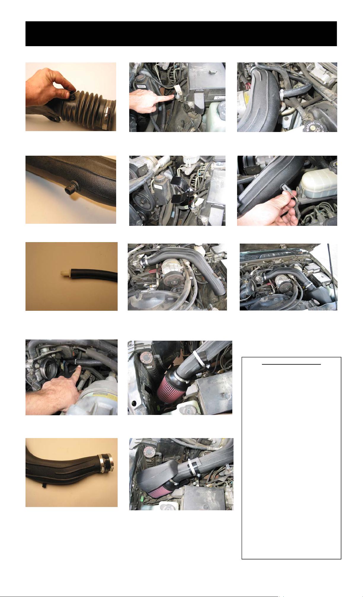
1. Turn off engine and disconnect negative battery
terminal and disconnect the air temperature
sensor electrical connection
2. Unclip the A.C. hose on the radiator shroud
5. Loosen the hose clamp on the i ntake tube
at the resonator box and detach
6. Lift out the stock intake from the vehicle 10. Loosen the hose clam connection from
9. Loosen the bolt that fastens the resonator
box to it’s mounting bracket
the resonator box to the throttle body
3. Loosen the hose clamp on the intake tube
at the air box
4. Prey up the two push pins that fasten
the intake tube to the radiator
7. Loosen the nut that retains the stock air box.
Remove the air box from the vehicle
8. Press down on the tab and lift and remove the
air box mounting bracket fro m the radiator core
support
11. Disconnect the crank case vent hose from the
valve cover and remove the resonator box
12 Install the rubber grommet into the hole in
the S&B cold air intake tube
12/11/2006
(Over)
Page 2
INSTALLATION INSTRUCTIONS (continued)
13. Install the air temperature sensor into
the S&B cold air intake tube
14. Install the air temperature sensor into the
S&B cold air intake tube
18. Locate the air box mounting stub. Slid e t he
1/4 washer down
19. Assemble the “saddle bra cket ” ass embly and
attach the bracket to the air box mount stud.
Tighten the bracket “semi tight” for adjustment
23. Connect the 1/2 crank case vent hose to the
S&B cold air intake
24. Connect the air temperature sensor elec t r ica l
connection
15. Push the 1/2x1/2 plastic hose mender
into the 1/2 vacuum tube.
16. Remove the crank case vent hose from
the resonator and attach it to the 1/2 hose
mender .Reconnect to the valve cover stem
17. Install the 2 3/4x2 adaptor sleeve on the
S&B cold air intake tube. Tighten the hose
clamps
20. Install the S&B cold air intake tube to the throttle body. Tighten the hose clamp s “semi- t igh t ”
21. Slide on the hose clamps up onto the S&B
cold air intake tube and saddle bracket . I nsta ll the
S&B high performance air filter onto the S&B cold
air intake tube
22. Install the air filter heat shield . Tight en all t he
hose clamps, and saddle br acke t assem b ly
25. Installation complete. Reconnect the negative
side of the battery
PERFORMANCE TESTING
∗ Engage parking brake and start your
engine. To ensure that the system was
installed properly, listen for abnormal
noises. If an air leak is detected, reinspect hoses and connections as they
may need to be tightened.
∗ S&B FILTERS RECOMMENDS THAT
YOU KEEP YOUR OEM INTAKE SYSTEM IN THE EVENT IT IS REQURIED
IN THE FUTURE.
∗ In order to maintain proper warranty, all
connections and components must be
checked periodically for realignment
and to tighten all connections. Failure
to do so will void your warranty.
∗ Use only S&B cleaning and oil products
to service your filter. Using other company’s oil and cleaner products may
void your warranty.
Please call (909) 947-0015 should you
have any questions or comments.
12/11/2006
(909) 947-0015 Telephone - (909) 947-0603 Fax
www.sbfilters.com
 Loading...