

Page 1
INSTALLATION INSTRUCTIONS
INSTALLATION INSTRUCTIONS
S&B P/N 75-2529-1
2001-2003 Ford
Explorer Sport, Sport
Trac, Ranger
4.0L V6 SOHC
* Kit may not fit vehicles with body
lift installed.
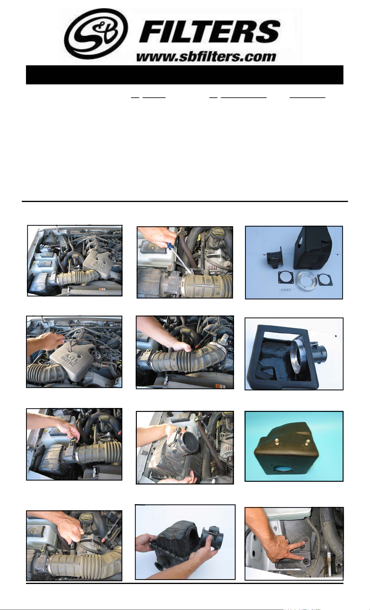
1. With the ignition switched off, disconnect
the negative battery terminal.
QTY PARTS LIST QTY PARTS LIST (continued)
1 3.5” - 2” Adapter 1 5/8” x 2.25” Hose
1 3.25” - 2” Adapter 4 1/4”-20 Hex Head Screws
1 Filter Adapter 4 1/4”’ Washers
1 Intake Tube 2 MAF Sensor Gaskets
1 Air Box 2 5/16” Acorn Nuts
1 Clear Lid 2 5/16” Jam Nuts
1 CARB S ticker 4 Sealing Washers
1 Air Filter 4 18-8 SS Pan Head Screws
4 #56 Hose Clamps 1 Rubber Grommet
Gently pry up on the clip and remove the
5.
MAF sensor wiring from the intake tube.
Locate the S&B air box and the MAF sensor
9.
adaptor hardware.
TOOLS REQUIRED
7/16 socket & Wrench
Flat head screwdriver
Phillips Head Screwdriver
7,10,13mm Wrench
4,5mm Allen
2. Remove the dust cover from the throttle
body housing.
3. Disconnect the electrical connection for the
MAF sensor.
6.
Loosen the hose clamps on the OE tube and
remove the intake tube
7.
Unclip the top of the OE air box and remove
the lid. Pull up on the air box and remove it from
the inner fender.
10.
Assemble the MAF sensor. Use a gasket
on both sides of the box opening.
11.
Assemble the 5/16 hardware provided, as
show below.
4.
Disconnect the crank case vent hose from
the OE intake tube.
Note:Some models have two vent hoses on the
intake tube.
5/1/2008
REV-B
(909) 947-0015 PHONE • (909) 947-0603 FAX
8.
Remove the MAF sensor from the OE
air box.
www.sbfilters.com
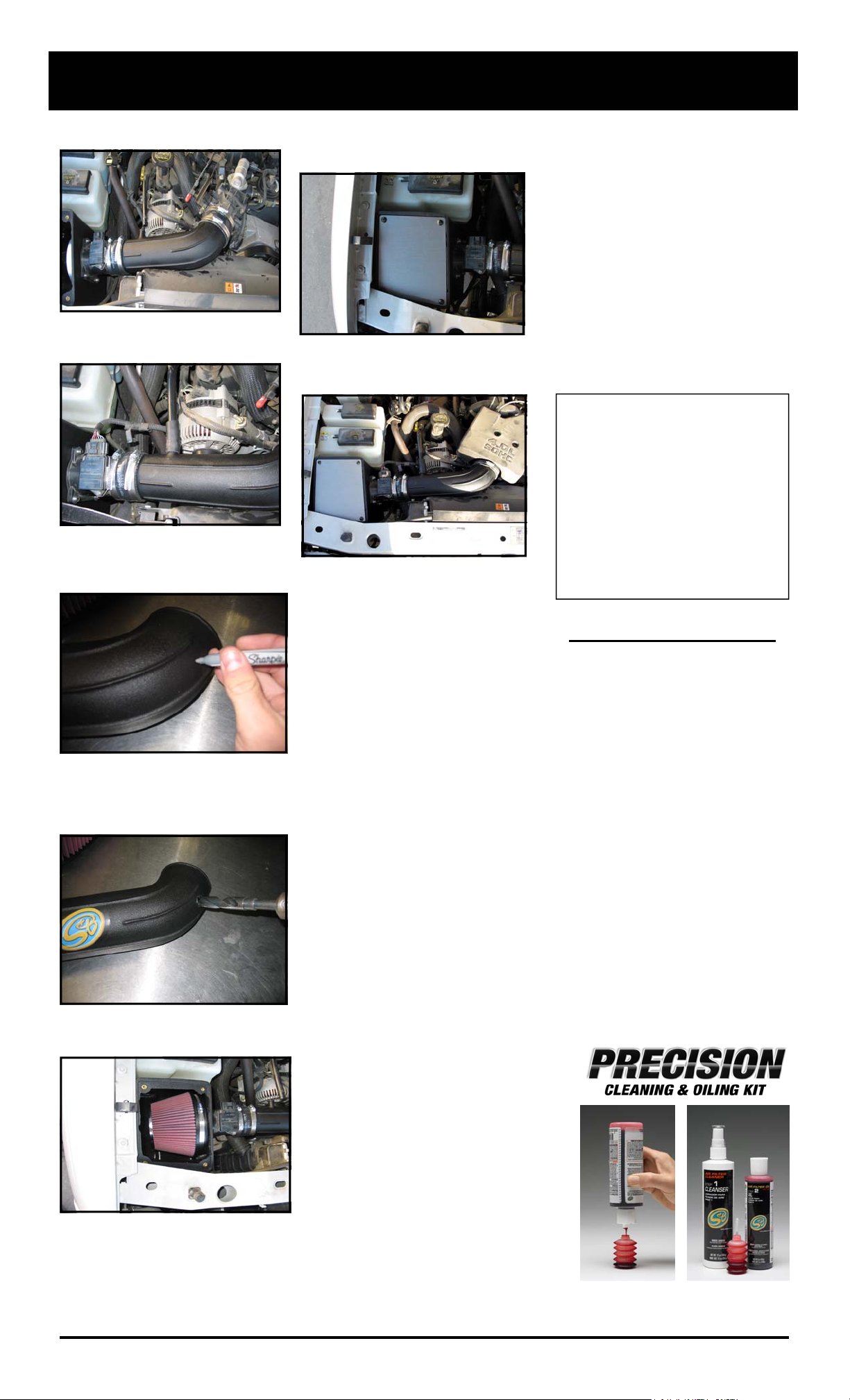
12.
Locate the box mount plate in the vehicle.
Push the S&B air box assembly down into the
OE grommets.
(OVER)
Page 2
INSTALLATION INSTRUCTIONS (continued)
13. Install the S&B intake tube as shown be-
low. Tighten the hose clamps
14
. Re-connect the MAF sensor electrical
connection. Re-connect the crank case vent
hose.
15.
On vehicles equipped with a second vent
hose, line up the vent hose to the intake tube
and mark the tube for drilling.
18. Attach the S&B clear lid using the provided
screws and conical washers.
(note: prototype lid pictured)
19. Replace the throttle body dust cover. And
re-connect the negative battery terminal. The
installation is now complete.
20. Recheck all connections to make
sure they are correct and tight.
Smog Certification Note:
The California Air Resource Board
(CARB) requires that an E.O.
identification label be applied to the
vehicle in order to pass a smog check
inspection when a High Performance
Intake Kit has been installed.
You must place the E.O. label provided
on or near the intake kit after installation
so that a smog check technician can
easily verify the E.O. number.
16.
After marking the tube, remove the tube
from the vehicle and drill a 5/8” hole and install
the provided grommet as shown. Reinstall the
intake tube. Install vent hose into intake tube.
17.
Install the S&B Air Filter.
21.
Adhere the C.A.R.B. exemption sticker in
plain sight under the hood.
PERFORMANCE TESTING
*Engage parking brake and start
your engine. Listen for abnormal
noises. If an air leak is detected,
re-inspect hoses and connections as
they may need to be repositioned
and tightened.
*S&B FILTERS RECOMMENDS
THAT YOU KEEP YOUR OEM
INTAKE SYSTEM IN THE EVENT
IT IS REQURIED IN THE FUTURE.
*In order to maintain your warranty,
all connections and components
must be checked periodically for
alignment and for proper tension on
all connections. Failure to do so will
void your warranty.
*Use only S&B Filter cleaning and
oil products to service your filter.
Using any other brand oil and or
cleaners may void your warranty.
5/1/2008
REV-B
Part No. 88-0005
Order online today at www.sbfilters.com
or though your local S&B Distributor
(909) 947-0015 Phone • (909) 947-0603 Fax
www.sbfilters.com
 Loading...