

Page 1
INSTALLATION INSTRUCTIONS
INSTALLATION INSTRUCTIONS
S&B Part # 75-2514-4
FORD
F-Series V8-4.6L, 5.4L
(Except Super Duty)
Expedition V8-436L, 5.4L
Navigator V8-5.4L SOHC
* Kit may not fit vehicles with a body
lift installed.
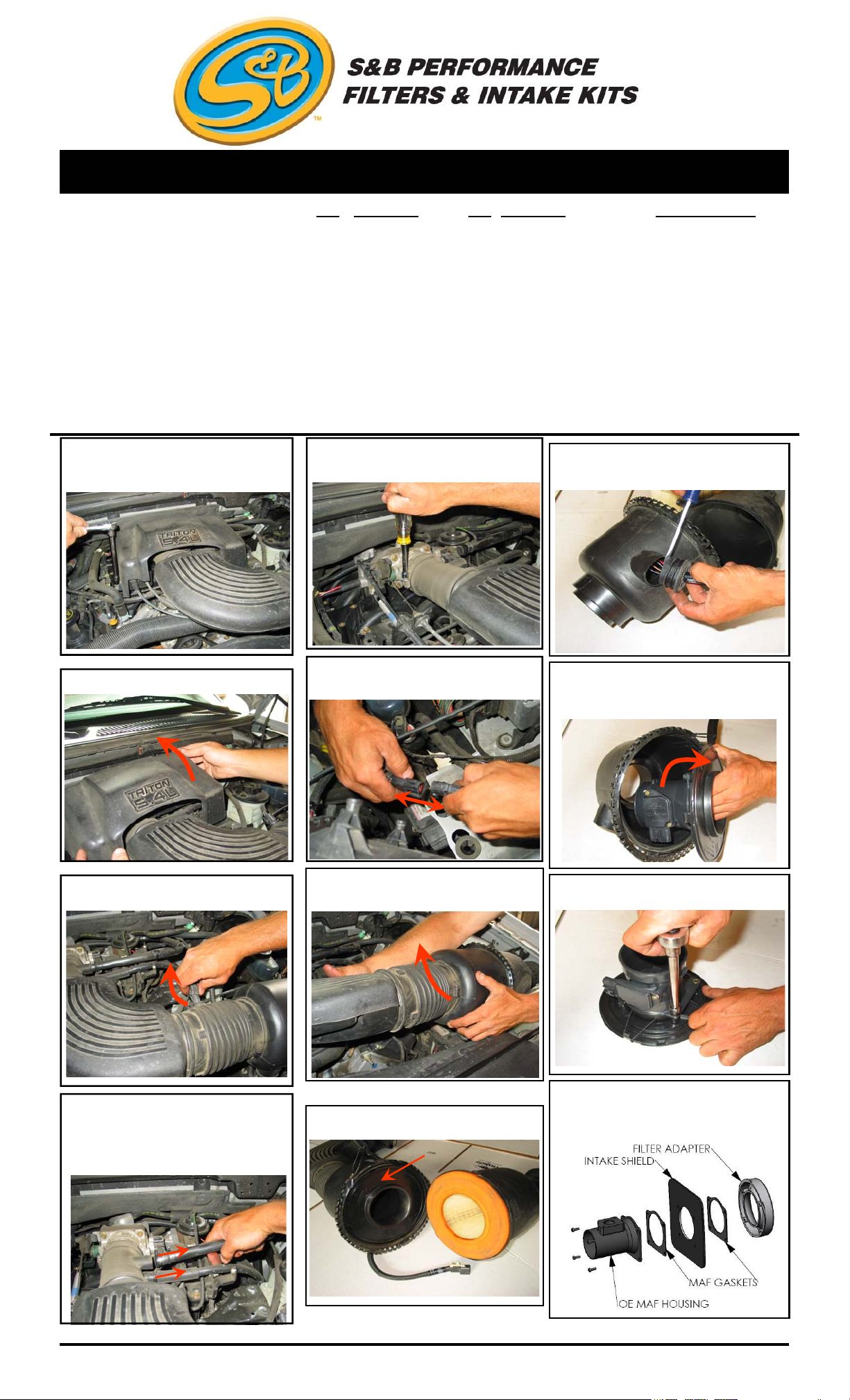
1. With the engine turned off, disconnect the
vehicle’s negative battery cable. Loosen the 3
bolts that secure the throttle body dust cover.
QTY PARTS LIST QTY PARTS LIST
1 3” / 3.5”Step Adapter 1 3/4” x 6” Hose
1 3.5”/ 4” Step Adapter 2 1/4”-20 Speed Nut
1 Intake Tube 2 1/4”-20 x 3/4” Bolt
1 Air Filter Shield 2 1/4” Fender Washer
1 Air Filter 2 Gasket
1 1/2” Grommet 1 Filter Adapter
2 #64 Hose Clamp 4 1/4-20 x 1” Bolt
2 #60 Hose Clamp 4 1/4 Washer
3 #8 Hose Clamp
5. At the throttle body, loosen the hose clamp
on the OE air tube.
9. Use a flat head screw driver to pry up the
rubber grommet, turn it side ways and push it
back through the hole.
TOOLS REQUIRED
Screw Driver (flat)
7/16” Socket
10mm Socket
Socket Extension
(Long)
Ratchet
13mm Wrench
2. Remove the dust cover.
3. Disconnect the electrical connection
for the air temperature sensor.
6. Disconnect the electrical connection for
the MAF sensor.
7. Pull up to release the OE air intake tube
assembly from the grommets. And remove it
from the vehicle.
10. Release the four clips that secure the MAF
sensor housing by pushing with a flat blade
screwdriver. Remove the housing and set the
wiring harness aside for now.
11. Remove the 4 bolts to separate the MAF
from the housing.
4. (a) On 4.6L Engines: Disconnect both the
air bypass valve line and the crankcase vent
line from the OE air intake tube.
4. (b) On 5.4L Engines: Disconnect both the
idle air control line and the crankcase vent
line from the OE air intake tube.
5.4L Engine shown.
3/17/2009
REV-D
(909) 947
8. Unclamp and open the air cleaner to gain
access to the MAF housing.
-0015 PHONE • (909) 947-0603 FAX
www.sbfilters.com
12. Assemble the MAF sensor, heat shield
and the filter adapter using the two gaskets
and 1/4-20 x 1” bolts provided.
(OVER)
Page 2
INSTALLATION INSTRUCTIONS (continued)
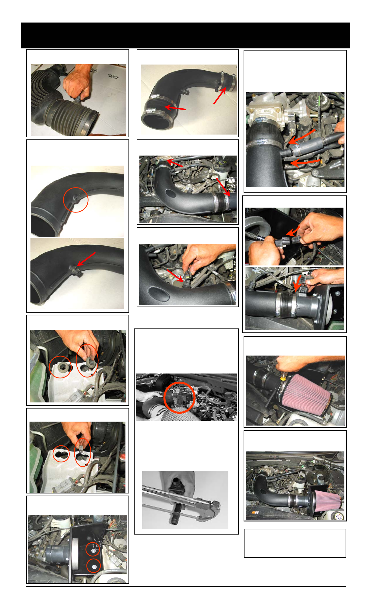
13. Twist and pull to remove the air
temperature sensor from the OE intake tube.
14. Install the rubber grommet provided into
the S&B intake tube and then carefully
insert the air temperature sensor into the
grommet.
18. Install the step adapters and appropriate
hose clamps onto the S&B intake tube.
19. Install the S&B intake tube onto the
throttle body and MAF sensor housing.
21.(b) On 5.4L Engines: Attach the provided
3/4”x6” hose to the crank case vent line and
secure both the vent and idle air control lines
to the S&B intake tube. Use the #8 Hose
Clamps. If the OE vent line allows, you may
cut the provided hose shorter as pictured
below.
22. Reconnect MAF sensor connections.
15. Remove the OE rubber grommets from
the inner fender bracket.
20. Reconnect the air temperature sensor
electrical connection..
21.(a) On 4.6L Engines: Cut the 3/4”x6” hose
down to about 3” to bridge the upper port
on the intake tube to the air bypass valve,
secure with #8 hose clamps.
Reconnect lower vent line to the intake tube’s
lower port, secure with #8 hose clamp.
23. Install the S&B air filter and tighten hose
clamp.
16. Install the speed nut clips to the inner
fender bracket.
17. Install the heat shield to the inner fender
bracket and secure using the 1/4”-20 x 3/4”
bolts and fender washers.
After installing the S&B Intake kit, some
4.6L engines may generate a whistling
sound at the air bypass valve. To eliminate the whistle remove the valve and
cut the flange of the air bypass valve just
up from the last barb, deburr the edge
and re-install the valve.
24. Inspect your installation, make sure
kit is properly positioned and all fasteners
are tight. Reconnect the battery.
25. Affix the C.A.R.B. exemption sticker in
plain sight under the hood near the intake
system.
3/17/2009
REV-D
(909) 947-0015 Phone • (909) 947-0603 Fax
www.sbfilters.com
Page 3

INSTALLATION INSTRUCTIONS (continued)
Smog Certification Note:
The California Air Resource Board
(CARB) requires that an E.O.
identification label be applied to the
vehicle in order to pass a smog
check inspection when a High
Performance Intake Kit has been
installed.
You must place the E.O. label
provided on or near the intake kit
after installation so that a smog
check technician can easily verify
the E.O. number.
∗
Engage parking brake and start your engine. Listen for abnormal noises. If an air leak is detected,
re-inspect hoses and connections as they may need to be repositioned and tightened.
∗ S&B FILTERS RECOMMENDS THAT YOU KEEP YOUR OEM INTAKE SYSTEM IN THE EVENT
IT IS REQURIED IN THE FUTURE.
∗ In order to maintain your warranty, all connections and components must be checked periodically for
alignment and for proper tension on all connections. Failure to do so will void your warranty.
∗ Use only S&B Filter cleaning and oil products to service your filter. Using any other brand oil and or
cleaners may void your warranty.
Please call (909) 947-0015
should you have any questions or comments.
PERFORMANCE TESTING
3/17/2009
REV-D
Part No. 88-0005
Order online today at www.sbfilters.com
or though your local S&B Distributor
(909) 947-0015 Phone • (909) 947-0603 Fax
www.sbfilters.com
 Loading...