

Page 1
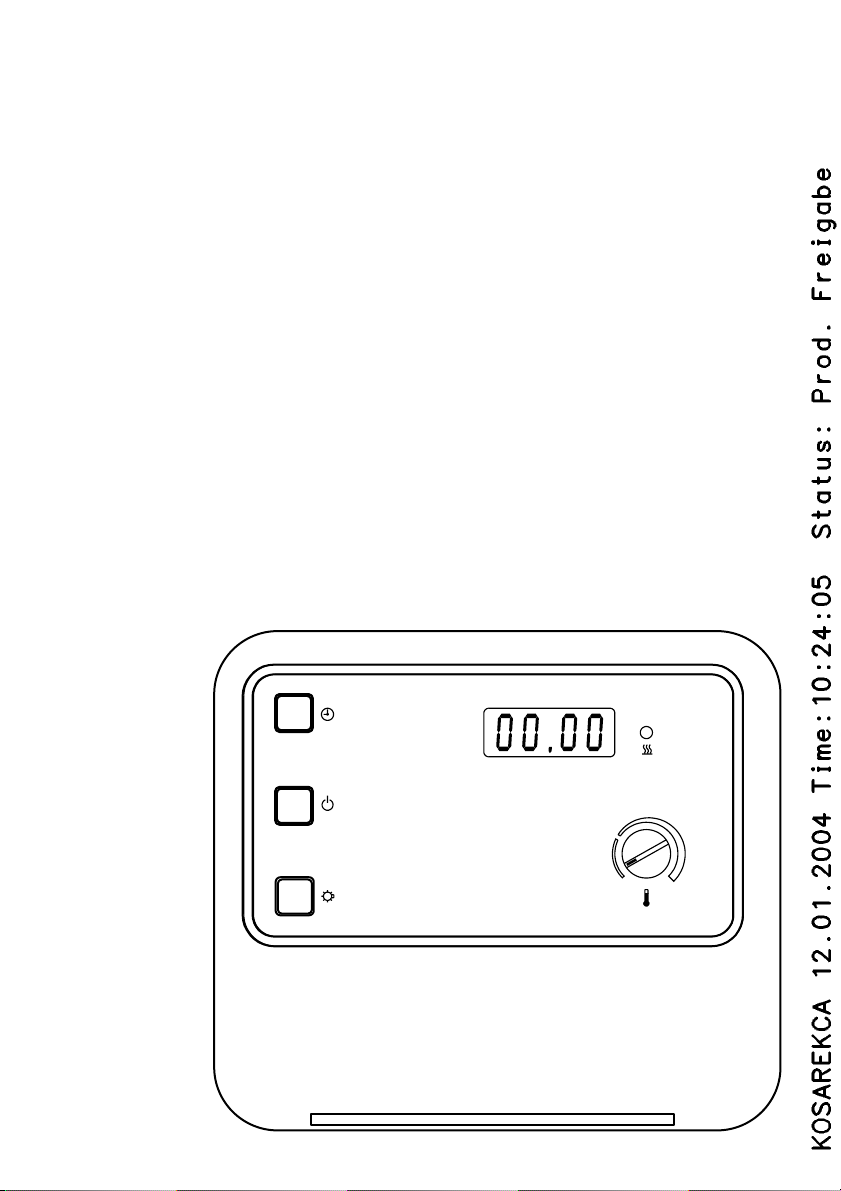
Saunasteuerung AS 21-15
Montageanweisung
Gebrauchsanweisung
DEUTSCH 2 ENGLISH 13
Page 2

Inhaltsverzeichnis
Teil 1 Montageanweisung nur für Fachpersonal
Allgemeine Sicherheitshinweise .................................................................................................................... 3
1 Montage der Saunasteuerung vorbereiten ............................................................................................. 4
2 Saunasteuerung montieren .................................................................................................................... 4
3 Montage der Saunasteuerung beenden ................................................................................................. 5
4 Innenraumtemperatur-Fühler F I mit Übertemperatur-Sicherung montieren ........................................... 5
5 Prüfungen .............................................................................................................................................. 6
6 Wechseln der defekten Sicherung für Innenraumbeleuchtung .....................................................................6
7 Rückmeldung bei auftretenden Fehlern .............................................................................................. 7
Teil 2 Gebrauchsanweisung für den Benutzer
Allgemeine Sicherheitshinweise ................................................................................................................. 8
1 Betriebsarten ........................................................................................................................................ 9
2 Anzeigen ............................................................................................................................................... 9
3 Fehlermeldungen ................................................................................................................................. 9
4 Steuerung und Innenraumbeleuchtung ein- / ausschalten ............................................................... 10
5 Schnell-Start ....................................................................................................................................... 10
6 Betrieb mit Vorwahlzeit ....................................................................................................................... 11
7 Reinigung ............................................................................................................................................11
8 Bei längeren Betriebspausen ..............................................................................................................11
9 Fehler und mögliche Abhilfe ............................................................................................................... 11
10 Wartung ...............................................................................................................................................11
11 Kundendienst ..................................................................................................................................... 12
Teil 3 Technische Daten
Technische Daten...................................................................................................................................... 12
2
Page 3
Montageanweisung nur für Fachpersonal
Sehr geehrter Monteur
Die Montage darf nur durch einen Elektrofach-
mann oder einer vergleichsweise qualifizierten
Person ausgeführt werden.
Arbeiten an der Sauna-Steuerung dürfen nur im
spannungsfreien Zustand ausgeführt werden.
Lesen Sie diese Montageanweisung sorgfältig vor
der Montage der Sauna-Steuerung. Damit nutzen
Sie alle Vorteile, die das Gerät bietet und beugen
Schäden vor.
Beim Auftreten besonderer Probleme, die in die-
ser Montageanweisung nicht ausführlich genug
behandelt werden, wenden Sie sich zu Ihrer eigenen Sicherheit an Ihren Lieferanten.
Eigenmächtige Änderungen oder Umbauten an
der Sauna-Steuerung sind aus Sicherheitsgründen nicht gestattet.
Bedeutung der in der Montageanweisung verwendeten Zeichen:
WARNUNG:
bei Nichtbeachtung besteht die Möglichkeit einer
schweren oder sogar tödlichen Verletzung.
VORSICHT:
bei Nichtbeachtung besteht die Möglichkeit von mittleren bis leichten Verletzungen oder Sachschäden.
HINWEIS:
gibt Anwendungstips und nützliche Informationen.
Bewahren Sie diese Montage- und Gebrauchsanweisung sorgfältig in der Nähe der SaunaSteuerung auf, um jederzeit Sicherheitshinweise
und wichtige Informationen zur Bedienung
nachschlagen zu können.
Allgemeine Sicherheitshinweise
Beachten Sie auch die speziellen Sicherheitshinweise der einzelnen Kapitel.
Installation:
In der Installation ist eine allpolige Abschaltmög-
lichkeit mit 3 mm Kontaktöffnung vorzusehen. (In
der Regel durch die Sicherung gegeben).
Bestimmungsgemäßer Gebrauch:
Vor dem Einschalten der Saunasteuerung und
beim Einschalten einer Vorwahlzeit (Zeit bis zum
Starten des Ofens) ist sicher zu stellen, dass keine brennbaren Gegenstände auf dem Ofen abgelegt sind.
Die Sauna-Steuerung AS 21-15 dient zum Steu-
ern und Regeln der Innenraumtemperatur im Bereich von 40 - 125 Grad Celsius,
Die Sauna-Steuerung AS 21-15 darf nur zum
Steuern und Regeln von 3 Heizkreisen mit maximal 5,0 kW Heizleistung pro Heizkreis eingesetzt werden.
Entsorgung:
Bitte entsorgen Sie Verpackungsmaterialien nach
den gültigen Entsorgungsrichtlinien.
Altgeräte enthalten wiederverwendbare Materiali-
en. Geben Sie deshalb Altgeräte nicht einfach
auf die nächste Mülldeponie, sondern erkundigen Sie sich bei Ihrer Stadt-oder Gemeindeverwaltung nach der Möglichkeit der Wiederverwertung.
3
Page 4
Montageanweisung nur für Fachpersonal
1 Montage der Saunasteuerung
vorbereiten 1
Die Saunasteuerung wird ausserhalb der Saunakabine oder gemäß der Kabinenhersteller-Empfehlung montiert.
Die elektrische Versorgung erfolgt als Festanschluss.
VORSICHT - Schäden am Gerät:
Die Saunasteuerung ist spritzwassergeschützt
(Schutzgrad IP 24). Trotzdem sollte die Saunasteuerung nicht direkt mit Wasser in Berührung kommen.
Die Saunasteuerung an einem trockenen Ort montieren. Die Umgebungsbedingungen von max. 40°
Celsius und einer maximalen Luftfeuchte von 95 Prozent einhalten.
1. Verriegelung 5 leicht eindrücken und das Ge-
häuse-Oberteil 6 abnehmen.
2. Kreuzschlitzschraube 16 mm Länge für die
obere Befestigungsbohrung 1 bis zum Abstand von 7 mm zur Saunawand eindrehen
(siehe Detail) und Gehäuse-Unterteil 4 an der
Rückseite einhängen.
2 Saunasteuerung
montieren 2 6
1. Leitungen des Temperatur-Fühlers F I mit Übertemperatur-Sicherung durch die Montageöffnung
6 in das Gehäuse-Unterteil 1 führen und gemäß dem Schaltplan an die Klemmleiste 3 anklemmen.
VORSICHT - Schäden am Gerät:
Die Sauna-Steuerung darf nur zum Steuern und Regeln von 3 Heizkreisen mit maximal 5,0 kW Heizleistung pro Heizkreis eingesetzt werden.
Die Fühlerleitungen müssen zu anderen Netz- und
Steuerleitungen getrennt verlegt werden.
3. Anschlußleitungen des Heizsystems durch die
Montageöffnung 8 in das Gehäuse-Unterteil
1 führen und gemäß dem Schaltplan an die
Klemmleisten 7/C anklemmen.
4. Netzanschlussleitungen (als Festverdrahtung)
durch die Montageöffnung 9 in das GehäuseUnterteil 1 führen und gemäß dem Schaltplan
an die Klemmleisten 7/C anklemmen.
5. Lichtleitungen durch die Montageöffnung A in
das Gehäuse-Unterteil 1 führen und gemäß
dem Schaltplan an die Klemmleisten 7/C anklemmen.
6. Zwei Kreuzschlitzschrauben, 20 mm Länge, in
die unteren Befestigungsbohrungen 5 eindrehen. Sicheren Sitz des Gehäuse-Unterteiles 1
prüfen.
4
Page 5
Montageanweisung nur für Fachpersonal
3 Montage der Saunasteuerung
beenden 3 6
1. Gehäuse-Oberteil 5 oben auf das GehäuseUnterteil 1 aufsetzen, nach unten schwenken
und bis zum hörbaren Einrasten drücken.
4 Temperatur-Fühler F I mit Über-
temperatur-Sicherung montieren
4 6
Der Temperatur-Fühler F I mit Übertemperatur-Sicherung wird in der Saunakabine circa 15 cm unterhalb
der Decke oberhalb des Heizsystemes, oder nach
Angaben des Kabinen-Herstellers montiert.
Der Fühler F I darf nur mit der beiliegenden bis
150 °C temperaturbeständigen Anschlussleitung
angeschlossen werden.
Ausserhalb der Sauna-Kabine kann die temperaturbeständige Anschlussleitung mit handelsüblichen
Leitungen verlängert werden.
VORSICHT - Doppelisolation ist notwendig:
Die Fühlerleitungen müssen zu anderen Netz- und
Steuerleitungen getrennt verlegt werden.
Einfach isolierte Leitungen müssen durch ein Rohr
(Doppelisolation) geschützt sein.
1. 2 x 2-polige Leitung 5 zum Montageort des
Fühlers F I 4 in der Kabinenwand verlegen und
mit Leitungsschellen fixieren.
2. Zwei Halbschalen 1 des Fühlers F I auseinan-
derziehen und vier Anschlüsse der temperaturbeständigen Anschlussleitung gemäß dem
Schaltplan anklemmen.
3. Runde Anschlussplatte 2 mit den Anschlüssen
quer in die Halbschalen 1 einlegen, Halbschalen 1 schliessen und mit den beiden Kreuzschlitzschrauben 3, Länge 9 mm verschrauben.
Sicheren Verschluss des Fühlers F I prüfen.
4. Prüfungen nach Kapitel 6, Prüfungen vorneh-
men.
5. Fühler FI 4 fluchtend mit der Ofenmitte im Ab-
stand von 15 cm zur Decke, oder nach Angaben
des Kabinen-Herstellers mit zwei Holzschrauben auf die Kabinenwand schrauben.
5
Page 6
Montageanweisung nur für Fachpersonal
5 Prüfungen
Die Prüfungen müssen von einem zugelassenen
Elektroinstallateur durchgeführt werden.
WARNUNG - Stromschlag:
Die nachfolgenden Prüfungen werden bei eingeschalteter Versorgungsspannung durchgeführt.
1. Prüfen der Erdklemmen-Kontaktierung.
2. Prüfung der Sicherheitsabschaltung bei unter-
brochener Leitung zum Temperaturfühler / -sicherung:
- Das Lösen der Leitung muss am Fühler durch-
geführt werden, dadurch wird die Fühlerleitung
in die Prüfung einbezogen.
- Beim Lösen der weißen ebenso beim Lösen
der roten Fühlerleitung muss das Heizsystem
selbständig abschalten.
3. Prüfen der Phasendurchschaltung L1, L2, L3
zu u,v,w.
Fehlerbeschreibung:
Relais flattern
Die eingestellte Temperatur wird nicht konstant
gehalten.
Störende Geräusche kommen aus der Steuerung.
Die Innenraumbeleuchtung leuchtet nicht.
Die Temperatursicherung hat ungeplant ausgelöst.
Heizung wird dauernd abgeschaltet
6 Wechseln der defekten Siche-
rung für Innenraumbeleuchtung
1 2 3
VORSICHT
Vor dem Öffnen des Gehäuse-Oberteiles Gerät
stromlos machen.
1. Drehknopf TEMPERATUR 3 bis zum An-
schlag nach links drehen und nach oben abziehen.
2. Verriegelung 5 leicht eindrücken und das Ge-
häuse-Oberteil 6 abnehmen.
3. Bedienteil 2 vorsichtig vom Gehäuse-Unterteil
4 abziehen.
4. Sicherung D austauschen.
HINWEIS:
Die Abdeckung 2 muss in den beiden seitlichen
Aufnahmen 4 geführt werden.
5. Abdeckung 2 in die beiden seitlichen Aufnah-
men 4 einsetzen und vorsichtig bis zum hörbaren Einrasten auf das Gehäuse-Unterteil 1
drücken.
6. Sicheren Sitz der Abdeckung 2 prüfen.
7. Gehäuse-Oberteil 5 oben auf das Gehäuse-
Unterteil 1 aufsetzen, nach unten schwenken
und bis zum hörbaren Einrasten drücken.
8. Drehknopf TEMPERATUR 3 vorsichtig auf-
drücken.
9. Sicheren Sitz des Drehknopfes TEMPERATUR
3 prüfen.
Fehler tritt unmittelbar nach dem Einschalten
auf.
Der Fehler tritt erst nach längerer Einschaltzeit
auf.
6
Page 7
Montageanweisung nur für Fachpersonal
7 Rückmeldung bei
auftretenden Fehlern
Sehr geehrter Monteur,
sollte wider Erwarten dieses Gerät Anlaß zur Beanstandung geben, bitten wir Sie, im Interesse einer
zügigen Reparaturabwicklung, um eine möglichst
genaue Fehlerbeschreibung.
Bitte senden Sie uns zu jeder Steuerung grundsätzlich auch den Temperaturfühler zurück.
Die Fehlermeldungen in der Anzeige bedeuten:
E-F1: Leitungskurzschluss / unterbrochene
Leitung / Ofenfühler defekt.
E- 12: Unterbrochene Leitung oder Scha
den an der Übertemperatur-Siche
rung.
E-P I: Schaden im Potentiometer 3 für
die Temperatur-Einstellung.
7 Fortsetzung
Sonstiges:
______________________________________
______________________________________
______________________________________
______________________________________
______________________________________
______________________________________
______________________________________
______________________________________
______________________________________
7
Page 8
Gebrauchsanweisung für den Benutzer
Sehr geehrter Anwender
Lesen Sie diese Gebrauchsanweisung sorgfältig
vor dem Gebrauch der Sauna-Steuerung. Damit
nutzen Sie alle Vorteile, die das Gerät bietet und
beugen Schäden vor.
Beim Auftreten besonderer Probleme, die in die-
ser Gebrauchsanweisung nicht ausführlich genug behandelt werden, wenden Sie sich zu Ihrer
eigenen Sicherheit an Ihren Lieferanten.
Eigenmächtige Änderungen oder Umbauten an
der Sauna-Steuerung sind aus Sicherheitsgründen nicht gestattet und lassen die Garantie erlöschen.
Technische Änderungen vorbehalten.
Bedeutung der in der Gebrauchsanweisung verwendeten Zeichen:
WARNUNG:
bei Nichtbeachtung besteht die Möglichkeit einer
schweren oder sogar tödlichen
VORSICHT:
bei Nichtbeachtung besteht die Möglichkeit von mittleren bis leichten Verletzungen oder Sachschäden.
HINWEIS:
gibt Anwendungstips und nützliche Informationen.
Feuergefahr
Allgemeine Sicherheitshinweise
Beachten Sie auch die speziellen Sicherheitshinweise der einzelnen Kapitel.
Bestimmungsgemäßer Gebrauch:
Vor dem Einschalten der Saunasteuerung und
beim Einschalten einer Vorwahlzeit (Zeit bis zum
Starten des Ofens) ist sicher zu stellen, dass keine brennbaren Gegenstände auf dem Ofen abgelegt sind.
Die Sauna-Steuerung AS 21-15 dient zum Steu-
ern und Regeln der Funktionen gemäß den Technischen Daten.
Die Sauna-Steuerung AS 21-15 darf nur zum
Steuern und Regeln von 3 Heizkreisen mit maximal 5,0 kW Heizleistung pro Heizkreis eingesetzt werden.
Entsorgung:
Altgeräte enthalten wiederverwendbare Materiali-
en. Geben Sie deshalb Altgeräte nicht einfach
auf die nächste Mülldeponie, sondern erkundigen Sie sich bei Ihrer Stadt-oder Gemeindeverwaltung nach der Möglichkeit der Wiederverwertung.
Bei längeren Betriebspausen:
Bei längeren Betriebspausen Hauptsicherungen der
Steuerung im Sicherungskasten ausschalten.
Bewahren Sie diese Montage- und Gebrauchsanweisung sorgfältig in der Nähe der SaunaSteuerung auf, um jederzeit Sicherheitshinweise
und wichtige Informationen zur Bedienung
nachschlagen zu können.
8
Page 9
Gebrauchsanweisung für den Benutzer - Abbildung 5
1 Betriebsarten
Die Saunasteuerung kann direkt als Schnell-Start
(siehe Kapitel 5) oder nach Ablauf einer eingestellten Vorwahlzeit - Zeit bis zum Einschalten des
Ofens (siehe Kapitel 6) gestartet werden.
2 Anzeigen
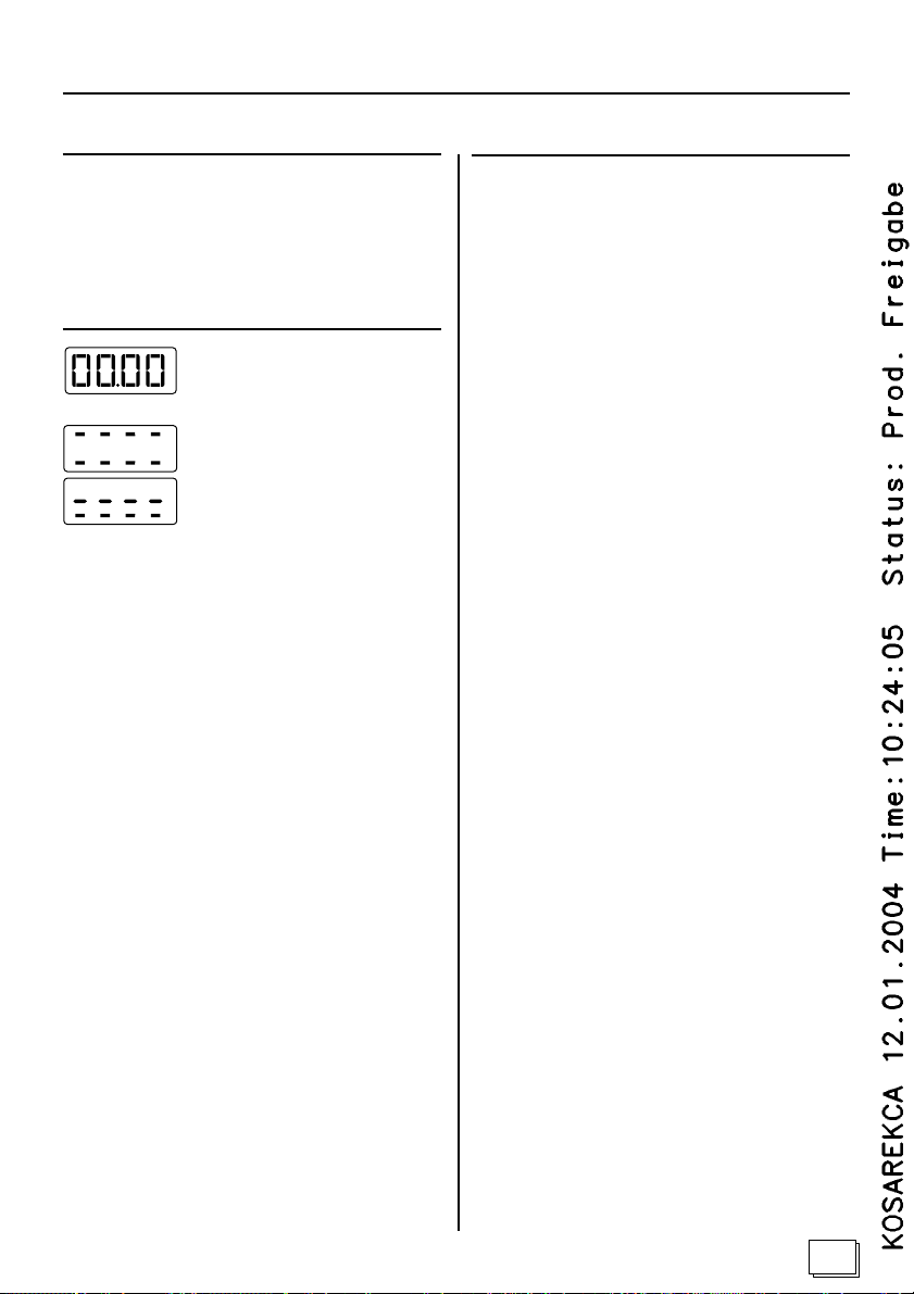
Selbsttest der Steuerung (Anzeige
blinkt).
Heizung ist in Betrieb.
Heizung ist nicht in Betrieb.
3 Fehlermeldungen
3.1 Fehler-Meldungen in der Anzeige 4:
Eine Fehler-Meldung signalisiert einen elektrischen
Defekt der Anlage.
Die Steuerung ist nicht mehr betriebsbereit:
1. Fehler-Meldung notieren.
2. Hauptsicherungen der Steuerung im
Sicherungskasten ausschalten.
3. Verständigen Sie Ihren Kundendienst.
4. Kennzeichnen Sie die Steuerung als defekt.
Mit den folgenden Fehlermeldungen in der Anzeige
4 können Sie Ihrem Kundendienst Informationen
über mögliche Fehler geben.
Die Fehlermeldungen bedeuten:
E-F1: Leitungskurzschluss / unterbroche
ne Leitung / Ofenfühler defekt.
E- 12: Unterbrochene Leitung oder Scha
den an der Übertemperatur-Siche
rung.
E-P I: Schaden im Potentiometer 6 für
die Temperatur-Einstellung.
3.2 Rote Kontroll-Leuchte 5 blinkt:
Die Steuerung schaltet beim Ansprechen der Übertemperatur-Sicherung die Heizung automatisch ab.
Die Steuerung ist nicht mehr betriebsbereit:
1. Hauptsicherungen der Steuerung im Sicherungskasten ausschalten.
2. Verständigen Sie Ihren Kundendienst.
3. Kennzeichnen Sie die Steuerung als defekt.
9
Page 10
Gebrauchsanweisung für den Benutzer - Abbildung 5
4 Steuerung und Innenraumbe-
leuchtung ein- / ausschalten
5 Schnell-Start
4.1 Steuerung einschalten
WARNUNG - Feuergefahr:
Vor dem Einschalten der Saunasteuerung
und beim Einstellen einer Vorwahlzeit (Zeit
bis zum Starten des Ofens) ist sicher zu stellen, dass keine brennbaren Gegenstände
auf dem Ofen abgelegt sind.
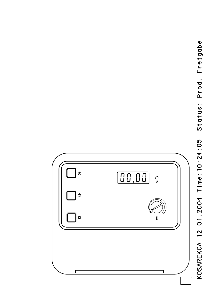
1. Steuerung am EIN / AUS Schalter 1 einschalten. Es erfolgt ein Selbsttest:
Die Kontroll-Leuchte 5 leuchtet kurz.
Ein Summer piept einmal.
In der Anzeige 4 blinkt: 00.00
Die Steuerung ist betriebsbereit.
4.2 Steuerung ausschalten
1. Nach beendetem Saunabad den
EIN / AUS Schalter 1 ausschalten.
Die Kontroll-Leuchte 5 erlischt.
Die Steuerung ist ausgeschaltet.
4.3 Die Sauna-Innenraumbeleuchtung ein- /
ausschalten
5.1 Steuerung einschalten
Steuerung gemäß Kapitel 4.1 einschalten.
5.2 Steuerung einstellen und starten
1. Mit dem Drehknopf 6 die gewünschte Temperatur einstellen.
Markieren Sie sich die Ihnen angenehme Temperatur, z.B. mit einem Bleistiftstrich.
2. Zeittaste 2 kurz drücken (kleiner 2 Sekunden)
Die Heizung beginnt zu heizen.
Die Kontroll-Leuchte 5 leuchtet permanent.
Wenn die gemessene Kabinentemperatur kleiner
als die eingestellte Solltemperatur ist, wird der Ofen
angesteuert. Der Ofen heizt.
Wenn die gemessene Kabinentemperatur größer
als die eingestellte Solltemperatur ist, wird der Ofen
nicht angesteuert.
5.3 Steuerung ausschalten
Steuerung gemäß Kapitel 4.2 ausschalten.
1. Taste 3 schaltet die Sauna-Innenbeleuchtung
EIN / AUS.
10
Page 11
Gebrauchsanweisung für den Benutzer - Abbildung 5
6 Betrieb mit Vorwahlzeit
6.1 Steuerung einschalten
Steuerung gemäß Kapitel 4.1 einschalten.
6.2 Vorwahlzeit einstellen
Es wird die Zeit bis zum Einschalten des Ofens eingestellt. Die minimal einstellbare Zeit beträgt 15 Minuten (Anzeige 00.15), die maximal einstellbare
Zeit beträgt 23 Std.und 45 Minuten (Anzeige
23.45).
1. Zeittaste 2 drücken und gedrückt halten.
Die Vorwahlzeit wird auf Null zurückgestellt und
zählt danach in 15 Minuten Schritten.
2. Zeittaste 2 loslassen.
Die Anzeige 4 zeigt die gewählte Vorwahlzeit.
Die Vorwahlzeit wird gestartet und die jeweils
verbleibende Zeit bis zum Start des Ofens angezeigt.
3. Mit dem Drehknopf 6 die gewünschte Temperatur einstellen.
Markieren Sie sich die Ihnen angenehme Temperatur, z.B. mit einem Bleistiftstrich.
Nach Ablauf der Vorwahlzeit wird der Ofen gestartet. Wenn die gemessene Kabinentemperatur kleiner als die eingestellte Solltemperatur ist, wird der
Ofen angesteuert. Die Steuerung heizt.
Wenn die gemessene Kabinentemperatur größer
als die eingestellte Solltemperatur ist, wird der Ofen
nicht angesteuert.
6.3 Vorwahlzeit löschen
1. Zeittaste 2 kurz drücken.
Die Vorwahlzeit wird gelöscht.
6.4 Steuerung ausschalten
7 Reinigung
VORSICHT - Schäden am Gerät:
Die Steuerung sollte nicht mit Wasser übergossen
oder sehr feucht gereinigt werden.
Benutzen Sie zum Reinigen ein leicht angefeuchtetes Reinigungstuch, das mit etwas milder Seifenlauge (Spülmittel) versehen ist.
8 Bei längeren Betriebspausen
Hauptsicherungen der Steuerung im Sicherungskasten ausschalten.
9 Fehler und mögliche Abhilfe
9.1 Automatische Zeitbegrenzung
Die Steuerung schaltet nach 6 Stunden oder
nach permanenter Heizzeit die Heizung automatisch ab.
Zum weiteren Betrieb den EIN / AUS Schalter
1 ausschalten und nach 10 Sekunden wieder
einschalten.
9.2 Innenraumbeleuchtung leuchtet nicht
EIN / AUS Schalter 1 ausschalten.
Hauptsicherungen der Steuerung im Siche-
rungskasten ausschalten.
Glühlampe austauschen.
Hauptsicherungen einschalten und Taste 3
betätigen.
Leuchtet die Innenraumbeleuchtung weiterhin
nicht, verständigen Sie bitte Ihren Kunden-
dienst oder Elektoinstallateur. (siehe Teil 1, Ka-
pitel 6)
10 Wartung
Die Steuerung ist wartungsfrei.
Im gewerblichen Einsatz ist die Steuerung ge-
mäß den aktuellen Unfall-Verhütungs-Vorschrif-
ten zu Warten / Prüfen.
11
Page 12
11 Kundendienst
Bitte tragen Sie Ihre Kundendienst-Adresse
hier ein:
Technische Daten
Thermische Sicherheit:
Ofen-Fühler mit Übertemperatur-Sicherung,
Abschalt-Temperatur 139°C.
Automatische Abschaltung nach max. 6 Stunden (je
nach Werkseinstellung).
Technische Daten
Umgebungsbedingungen:
Lagertemperatur: -25°C bis + 70°C
Umgebungstemperatur: -10°C bis + 40°C
Luftfeuchtigkeit: max. 95 %
Minimale Temperaturbeständigkeit
der Anschlussleitungen:
Heizsystem-, Licht-, Ofenleitungen mindestens
150°C Temperaturbeständigkeit.
Maximale Leitungslängen:
Ofenfühler: 3 m
Steuerung:
Schaltspannung / dreiphasig 3N: 400 V
Frequenz: 50 Hz
Schaltleistung / Heizung AC 1: 3 x 5 kW
Schaltstrom pro Phase / Heizung AC 1: 23 A
Nennspannung: 230 V
Min. / Max. Aufnahmeleistung: 7 / 12 VA
Schutzart (Spritzwassergeschützt): IP X4
Anschluss an das Versorgungsnetz als Festverdrahtung (Festanschluss).
Einstellbereiche:
Temperatur: 40-125 Grad Celsius
über dem Ofen.
Vorwahlzeit: in 15 Minuten Stufen
Min. Vorwahlzeit. 15 Minuten
Max. Vorwahlzeit: 23 Stunden 45 Minuten
Heizdauer: Automatische Abschaltung nach 6
Stunden *.
* Bei der Verwendung in Wohnblöcken, Hotels oder
ähnlichen Standorten, muss der Betriebszeitraum
auf maximal 12 Stunden begrenzt sein.
12
Licht:
AC1 Schaltstrom: 1A
Ausgabe: 09-2003 Ident-Nr. 150 73 20
Page 13
ENGLISH
Sauna control AS 21-15
Assembling Instructions
Operating instructions
13
Page 14

Table of Contents
Part 1 Assembling Instructions for Specialist Staff Only
General Safety Information ......................................................................................................................... 15
1 Preparing for assembling the sauna control ......................................................................................... 16
2 Assembling the sauna control .............................................................................................................. 16
3 Finishing the assembly of the sauna control ......................................................................................... 17
4 Installing the interior temperature sensor F I with overtemperature fuse ............................................... 17
5 Tests .................................................................................................................................................... 18
6 Changes of the defective fuse for interior lighting .......................................................................... 18
7 Feedback messages of occurring errors ........................................................................................... 19
Part 2 Operating instructions for the User
General safety information ........................................................................................................................ 20
1 Operating modes ................................................................................................................................ 21
2 Displays .............................................................................................................................................. 21
3 Error messages .................................................................................................................................. 21
4 Turning on / off the control and the interior lighting .......................................................................... 22
5 Quick-Start .......................................................................................................................................... 22
6 Operation at selected time ................................................................................................................. 23
7 Cleaning .............................................................................................................................................. 23
8 Pausing operation for a longer time period ....................................................................................... 23
9 Errors and possible remedies ............................................................................................................ 23
10 Maintenance ....................................................................................................................................... 23
11 Customer service ............................................................................................................................... 24
Part 3 Technical Data
Technical data ........................................................................................................................................... 24
14
Page 15
Assembling Instructions for Specialist Staff Only
Dear Assembler
Assembling may be performed by an electrician or
a comparatively qualified person only.
Make sure the sauna control has been disconnec-
ted from the main power supply before starting
work.
Read the assembling instructions carefully, before
assembling the sauna control. In doing so you will
utilize all the benefits of the device and you will
prevent damages.
Should particular problems occur, which are not
sufficiently dealt with in these assembling instructions, to protect yourself, turn to your supplier.
Unauthorized changes or modifications of the sau-
na control are not permitted due to safety reasons.
We reserve the right to make technical changes.
Meaning of characters in the assembling instructions:
WARNING:
if not observed you may be subject to severe or even
deadly injury.
CAUTION:
if not observed you may be subject to medium to
light injuries or material damages.
NOTE:
gives advice concerning applications and useful information.
General safety information
Follow also the special safety information of
each chapter.
Installation:
On installation an all-pin disconnection turn-off
needs to be provided with a 3 mm contact opening. (Generally provided for by the fuse).
As directed use:
Prior to turning on the sauna control and to set-
ting the desired time (time until the stove starts)
make sure that no combustible objects have
been placed on top of the stove.
The purpose of the sauna control AS 21-15 is to
control the temperature of the interior within the
range of 40 - 125 degrees Celsius.
You are only allowed to use the sauna control
AS 21-15 for controlling 3 heating circuits with a
maximum heating capacity of 5.0 kW per heating
circuit.
Disposal:
Please dispose of packaging materials in accordan-
ce with applicable disposal regulations.
Old used devices contain recycable materials.
Therefore please do not simply dispose of them
at the nearest landfill, but do inquire at the administrative offices of your city or district about the
possibility of recycling.
Keep these assembling and operating instructions near the sauna control for quick and
easy reference regarding important information
for safety and operation.
15
Page 16
Assembling Instructions for Specialist Staff Only
1 Preparing the Assembly of the
Sauna Control 1
Mount the sauna control on the exterior of the sauna cabin or in accordance with the recommendations of the manufacturer.
A non-detachable supply connection provides the electrical power supply.
CAUTION - Damages of Device:
The sauna control is protected from splashing water (protection degree IP 24). Nevertheless the sauna controls should not come in contact with water.
Mount the sauna control at a dry location. With environmental conditions of 40° Celsius and a maximum
of 95 percent humidity.
1. Interlock 5 slightly push in and lift off the top
of the enclosure 6.
2. Recessed head screw 16 mm length for the up-
per mounting hole 1 tighten up to a gap of 7
mm to the sauna wall (refer to detail) and hang
up bottom of enclosure 4 at the back side.
2 Assembling the Sauna Control
2 6
1. Guide the circuit lines of the temperature sensor
F I with overtemperature fuse through the mounting opening 6 into the bottom of the enclosure 1 andin accordance with the circuit diagram
clamp to the terminal strip 3.
CAUTION- Damages of Device:
You are only allowed to use the sauna control ASV
for controlling 3 heating circuits with a maximum
heating capacity of 5.0 kW per heating circuit.
The sensor lines have to run separately to other circuit and control lines.
3. Guide the supply cable of the heating system th-
rough the mounting opening 8 into the bottom of the enclosure 1 and in accordance with
the circuit diagram (page 9) clamp to the terminal strip 7/C.
4. Guide the power supply cable (as non-detacha-
ble wiring) through the mounting opening 9
into the bottom of the enclosure 1 and in accordance with the circuit diagram clamp to the
terminal strip 7/C.
5. Guide the lighting circuit lines through the
mounting opening into the bottom of the enclosure 1 and in accordance with the circuit diagram clamp to the terminal strip 7/C.
6. Screw two recessed head screws, 20 mm in
length, into the bottom mounting holes.5
Check for secure fit of the bottom of the enclosure 1.
16
Page 17
Assembling Instructions for Specialist Staff Only
3 Finishing the Assembly of the
Sauna Control 3 6
1. Place top of enclosure 5 on top of the bottom
of the enclosure 1 rotate it to bottom and push
until you hear it lock.
4 Mount temperature sensor F I with
overtemperature fuse 4 6
Mount the temperature sensor F I with overtemperature fuse in the sauna cabin about 15 cm below the
ceiling and above the heating system, or in accordance with specifications of the cabin manufacturer.
The sensor F I can only be connected with the attached 150°C temperature-resistant connecting
line.
On the outside of the sauna cabin the temperatureresistant connecting line can be extended with customary lines.
CAUTION - Double insulation is required:
The sensor lines have to run separately to other circuit and control lines.
Single insulated lines have to be protected with a
pipe (double insulation).
1. Run two x two-pin line 5 to mounting site of
sensor FI 4 at the cabin wall and fix in position
with wiring clips.
2. Separate two half shells 1 of the sensor F I
and clamp to four terminal connectors of the
temperature-resistant connection line according
to the circuit diagram.
3. Insert round adaptor plate 2 with the connec-
tion cross-wise in the half shells, 1 close half
shells 1 and tighten with the two recessed
head screws 3 which are 9 mm in lenght.
Check for secure locking of the sensor F I.
4. Run tests according to chapter 6, Tests.
5. Bolt sensor F I 4 with two wooden screws to
the cabin wall in aligment with the middle of the
heater, keep a distance of 15 cm to the ceiling,
or in accordance with specifications of the cabin manufacturer.
17
Page 18
Assembling Instructions for Specialist Staff Only
5 Tests
Tests have to be conducted by an authorized electrical engineer.
WARNING - Danger of Electric Shock:
The following tests have to be conducted with supply voltage turned on.
1. Test contact to ground terminal.
2. Test the safety shutdown with interrupted line to
the temperature sensor / fuse.
- The line has to be loosend at the sensor, so
that the sensor line is included in the test.
- When loosening the white or the red sensor li-
nes the heating system has to turn off by itself.
3. Test the phase interconnection L1, L2, L3 to
u,v,w.
Error description:
Relay wobble.
The set temperature is not kept constant.
Disturbing sounds come from the control.
The interior lighting does not light.
The temperature fuse has been triggered unexpectedly.
Heater will be continuously turned off.
Error occurs immediately after turn-on.
6 Changes of the defective fuse
for interior lighting 1 2 3
CAUTION
Before opening the top of enclosure diconnect the
unit from the power supply.
1. Rotary knob TEMPERATURE 3 turn to the left
until limit stop and pull upward.
2. Interlock 5 slightly push in and lift off the top
of the enclosure 6.
3. Operating device 2 carefully pull off from the
bottom of the enclosure 4.
4. Change the fuse D.
NOTE!
The cover 2 has to be guided into holding fixtures
at the sides 4.
5. Insert cover 2 into both holding fixtures at the
sides 4 and carefully push down on the bottom of the enclosure until you hear it lock 1.
6. Check for secure fit of the cover.
7. Place top of enclosure 5 on top of the bottom
of the enclosure 1 rotate it to bottom and push
until you hear it lock.
8. Rotary knob TEMPERATURE 3 carefully
press down.
9. Check for secure fit of the rotary knob TEMPE-
RATURE 3.
Error occurs after it has been turned on for a
while.
18
Page 19
Assembling Instructions for Specialist Staff Only
7 Feedback of
Occurring Errors
Dear Assembler,
Should, against expectations, there be reasons for
complaints regarding this device, we would ask you
to please describe the error as accurately as possible to allow for speedy repair processing.
For every returned control please always include
the temperature sensor(s).
Error messages in the display indicate:
E-F1: short in line / break in
line/ stove sensor defective
E- 12: break in line or defective
overtemperature protector.
E-P I: damage of the potentiometer 6
for temperature setting
7 Continued
Miscellaneous:
______________________________________
______________________________________
______________________________________
______________________________________
______________________________________
______________________________________
______________________________________
______________________________________
______________________________________
19
Page 20
Operating instructions for the user
Dear User
Carefully read the operating instructions before
using the control . By doing so you will utilize all
the benefits of the device and you will prevent
damages.
To protect yourself, turn to your supplier should
particular problems occur, which are not sufficiently dealt with in these assembling instructions.
Unauthorized changes or modifications of the
control are not permitted due to safety reasons.
We reserve the right to make technical chan-
ges.
Meaning of characters in the operating instructions:
WARNING:
if not observed you may be subject to severe or even
deadly injury.
CAUTION:
if not observed you may be subject to medium to
light injuries or materials may be damaged.
NOTE:
gives advice concerning applications and useful information.
General Safety Information
Follow the special safety information of each
chapter.
As directed use:
Prior to turning on the sauna control and to set-
ting the desired time (time until the stove starts)
make sure that no combustible objects have
been placed on top of the stove.
The control AS 21-15 is used to control the
functions in accordance with the technical data.
Do not place any objects on top of the stove.
You are only allowed to use the control AS 21-
15 for controlling 3 heating circuits with a maxi-
mum heating capacity of 5.0 kW per heating
circuit.
Disposal:
Old used devices contain recyclable materials.
Therefore please do not simply dispose of them
at the nearest landfill, but do inquire at the ad-
ministrative offices of your city or district about
the possibility of recycling.
Pausing operation for a longer time period
When pausing operation for a longer time period,
shut off the main fuses of the control in the fuse
box.
Fire hazard
Keep these assembling and operating instructions near the control for quick and easy reference regarding important information for safety
and operation.
20
Page 21
Operating instructions for the user - Figure 5
1 Operating modes
You can start the sauna control directly via the
Quick-Start feature (refer to chapter 5) or after the
set desired time has elapsed - time until the stove
turns on (refer to chapter 6).
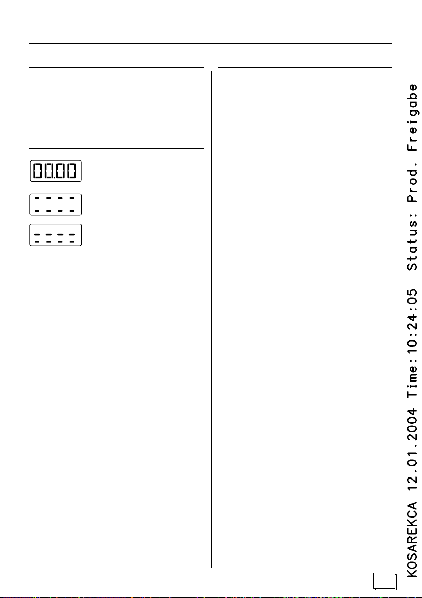
2 Displays
Self-testing of the control (display
flashes).
Heater is running.
Heater is not running.
3 Error messages
3.1 Displayed error messages 4:
An error message signals an electrical defect of the
system.
The control is no longer ready-to-operate:
1. Write down the error message.
2. Switch off the main fuses of the control in
the fuse box.
3. Contact customer service.
4. Mark the control as being defective.
Using the following displayed error messages 4
you can inform customer service of possible errors/
defects.
The error messages mean:
E-F1: short in line / break in
line/ stove sensor defective
E- 12: break in line or defective
overtemperature protector.
E-P I: damage of the potentiometer 6
for temperature setting
3.2 Red signal lamp 5 flashes:
Automatically, the control will turn off the heater if
the overtemperature protector has responded.
The control is no longer ready-to-operate:
1. Shut off the main fuses of the control in the
fuse box.
2. Contact customer service.
3. Mark the control as being defective.
21
Page 22
Operating instructions for the user - Figure 5
4 Turning on / off the control and
the interior lighting
5 Quick-Start
4.1 Turning on the control
WARNING - Fire hazard:
Prior to turning on the sauna control and
when selecting the start-time (time until the
stove starts) make sure that no combustible objects have been placed on top of the
stove.
1. Turn on the control with the ON / OFF key 1.
A self-test follows:
Briefly the signal lamp 5 lights up.
A buzzer will beep once.
The display 4 flashes: 00.00
The control is ready-to-operate.
4.2 Turning off the control
1. After your sauna bath press the ON / OFF key
1.
The signal lamp 5 will go out.
The control has been turned off.
4.3 Turning the sauna interior lighting on / off
5.1 Turning on the control
Turn on the control according to chapter 4.1.
5.2 Adjusting and starting the control
1. Set the desired temperature using the knob 6.
Note (with a pencil mark) the temperature most
agreeable to you.
2. Briefly press time key 2 (less than 2 seconds)
The heater starts.
The signal lamp 5 is lit constantly.
If the cabin temperature measured is less than the
desired temperature set, the stove will be respond.
The stove will heat.
If the cabin temperature measured is greater than
the desired temperature set, the stove will not be
respond.
5.3 Turning off the control
Turn off the control according to chapter 4.2.
1. Key 3 turns sauna interior lighting ON / OFF.
22
Page 23
Operating instructions for the user - Figure 5
6 Operation at selected time
6.1 Turning on the control
Turn on the control according to chapter 4.1.
6.2 Setting the desired time
You can set the time, after which the stove is to
start heating. You can set the time at a minimum of
15 minutes (display 00.15), or at a maximum of 23
hrs. and 45 minutes (display 23.45).
1. Press and hold time key 2.
The desired time is reset to zero and from there-
on will count at 15 minute increments.
2. Release the time key 2.
The display 4 indicates the desired time.
The time set starts and the remaining time until
the stove will start is indicated.
3. Set the desired temperature using the
knob 6.
Note (with a pencil mark) the temperature most
agreeable to you.
7 Cleaning
CAUTION - Damages of Device:
Do not pour water on the control or clean it with a
wet cloth.
For cleaning please use a cleaning cloth, which has
been slightly moistened with a mild soapy solvent (
dish detergent).
8 Pausing operation for a longer
time period
Shut off the main fuses of the control in the fuse
box.
9 Errors and possible remedies
9.1 Automatic time limitation
Automatically, the control will turn off the hea-
ting after 6 hours of continuous heating.
To continue operation turn off the ON / OFF
switch 1 and turn it on again after 10 seconds.
9.2 Interior lighting does not work
After the desired time set has elapsed the stove will
be started. If the cabin temperature measured is
less than the desired temperature set, the stove will
be respond. The stove will heat.
If the cabin temperature measured is greater than
the desired temperature set, the stove will not be
respond.
6.3 Cancelling the desired time
1. Briefly press the time key 2.
The desired start-time will be cancelled.
6.4 Turning off the control
Turn off the control according to chapter 4.2.
Turn off the ON / OFF 1 switch.
Shut off the main fuses of the control in the
fuse box.
Replace the light bulb.
Switch on the main fuses and press key 3.
Contact customer service or the electrical engi-
neer, if the interior light still does not work. (look
at part 1, chapter 6)
10 Maintenance
The control is maintenance-free.
Maintain and test the control in accordance
with prevailing regulations regarding accident
prevention procedures during commercial use.
23
Page 24
12 Customer service
Please write down the address of your custo-
mer service here:
Technical Data
Thermal safety:
Stove sensor with overtemperature protector,
shutdown temperature 139°C.
Automatic shutdown after, at the maximum of 6
hours (depending on the factory setting).
Technical Data
Environmental conditions:
Storage temperature: -25°C to + 70°C
Ambient temperature: -10°C to + 40°C
Air humidity: max. 95 %
Minimum temperature stability
of the connecting lines:
Heating system, lighting circuits, and stove lines are
heat-resistant to at least 150°C .
Maximum length of lines:
stove sensor: 3 m
Control:
Switching voltage / three-phase 3N: 400 V
Frequency: 50 Hz
Switching capacity / heating AC 1: 3 x 5 kW
Switched current each phase /
heating AC 1: 23 A
Nominal voltage: 230 V
Min. / max. pick-up capacity: 7 / 12 VA
Degree of protection (splash-proof): IP X4
Range of adjustment:
Temperature: 40-125 degrees Celsius
above the stove.
Selected start-time: in 15 minute increments
Min. of selected start-time. 15 minutes
Max.of selected start-time: 23 hours 45 mi
nutes
Duration of heating: Automatic shutdown after 6
hours:
* If used in apartment buildings, hotels, or similar
buildings, the operational timeframe has to be limited to 12 hours.
24
Connection to the main circuit as permanent wiring
(non-detachable connection).
Light:
AC1 switched current: 1A
Edition: 09-2003 Ident-No. 150 73 20
 Loading...