

PARTS & SERVICE MANUAL for RB-33VS Conveyor Bun Toaster
The RB-33VS Conveyor Bun Toaster is engineered for efficient,
dependable service throughout the years. Like any piece of fine
equipment with moving parts and broad temperatures ranges,
physical wear takes it toll. When this happens, the information
found in this Manual will prove very helpful.
NOTICE
Although the instructions are easy to follow, all
repair procedures, should be carried out by a
1200-JDM 07105
Savory Certified Service Technician.
RB-33VS PARTS REPLACEMENT INSTRUCTIONS
WARNING
DISCONNECT TOASTER FROM POWER SOURCE
BEFORE ATTEMPTING ANY SERVICE PROCEDURES
General information
The information on the following pages will describe
how to replace the most common components of the
RB-33VS Toaster. Though the instructions are easy
to follow, the work should be handled by a qualified
Service Technician.
A Case Cover Removal:
1. Remove reflector tray and chute toast tray.
2. Remove the screws securing front trim panel and
remove panel.
3. Remove left front panel.
4. Remove the screws securing control panel to unit and
carefully pull control panel outward and towards
center of toaster.
5. When replacing cover, be sure tabs on sides and top
of cover fit into grooves on back of toaster.
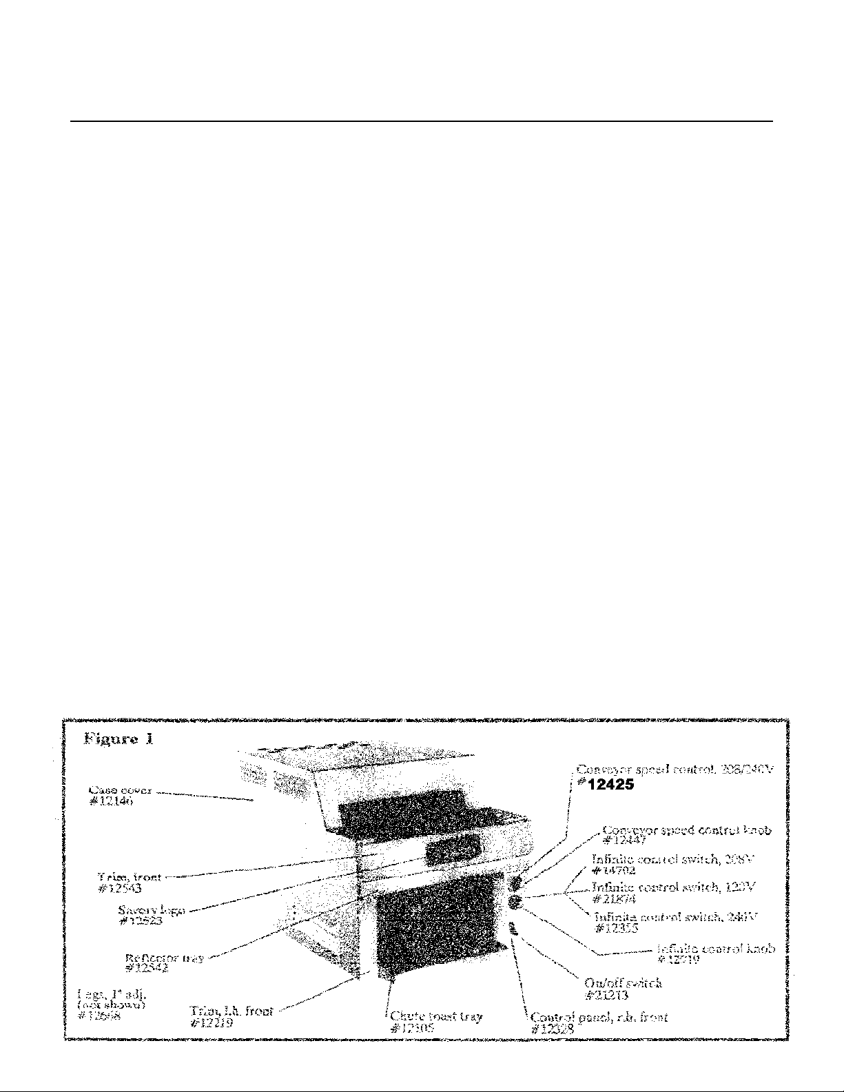
C Conveyor Speed Control/P.C. Board
(Figure 1 & 2)
1. Remove case cover. (Section A)
2. Pull off speed control knob and remove the nut
securing the control to the panel. Pull out
control from back of control panel.
3. Cut wire harness tie and remove speed control
wires.
4. Disconnect motor lead and on/off lead from P.C.
board terminals.
5. Remove 2 screws and nuts securing P.C. board
to floor of unit and remove P.C. board assembly.
6. Reverse this procedure to install new assembl;y.
(Refer to wiring diagram)
B Main Power On/Off Switch
(Figures 1 & 2)
1. Remove the case cover. (Section A)
2. Disconnect the 2 wires at the on/off switch terminal
ends. Note correct orientation of wires
3. Remove the 2 slotted screws securing switch to
control panel.
4. The on/off switch can now be removed from the back
of the control panel.
5. Reverse this procedure to install new switch.
(Refer to wiring diagram)
D Infinite Control Switch
(Figure 1 & 2)
1. Remove case cover. (Section A)
2. Pull off heater control knob to gain access to 2
slotted screws that secure control to control
panel. Remove these 2 screws.
3. Disconnect the wires from the control terminal
ends, noting proper orientation of wires.
4. Install new control from back of control panel
and secure with 2 slotted screws.
5. Re-attach wires to terminal ends. (Refer to
wiring diagram)
2
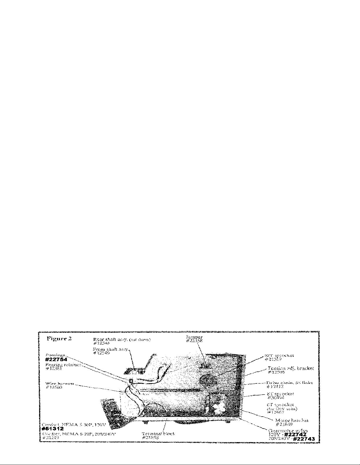
E Terminal Block
(Figure 2)
1. Remove case cover. (Section A)
2. Remove the wires at the terminal ends noting
proper wire orientation.
3. Remove the 2 nuts securing the terminal block to
the floor of the toaster.
4. Reverse this procedure to install new terminal
block. (Refer to wiring diagram)
F Gearmotor and Motor
Sprocket
(Figure 2, 6 & 7)
1. Remove case cover. (Section A)
2. Loosen the 4 motor mounting screws and slide
motor to achieve slack in the drive chain. Remove drive chain.
3. Loosen set screw on motor sprocket and remove
sprocket.
4. Remove the 4 motor mounting screws and lift out
motor.
5. Disconnect 2 wire leads from motor, one at wire
connector and the other at the terminal block.
6. Reverse this procedure to install new motor.
(Refer to wiring diagram)
G Resistor
Not shown
1. Remove case cover. (Section A)
2. Disconnect wires from resistor.
3. Remove hardware securing resistor bracket and
resistor.
4. Reverse this procedure to install new resistor.
(Refer to wiring diagram)
SPECIAL NOTE: The RB-33VS is no longer built
with the resistor installed.
H Drive Chain
(Figure 2 & 6)
1. Remove case panel. (Section A)
2. Loosed, but do NOT remove, the 4 motor
mounting screws. Slide motor to achieve slack in
drive chain and remove chain.
3. When installing new chain, check for proper chain
orientation and tension.
I Conveyor Shaft Sprocket
(Figure 2, 6 & 7)
1. Remove right side panel. (Section A)
2. Remove drive chain. (Section H)
3. Loosen set screw on hub of sprocket and slide sprocket
off shaft.
4. When installing new sprocket, make sure set screw rests
in hole on shaft.
5. Replace drive chain. (Section H)
J Conveyor Belt
(Figure 2 & 8)
1. Remove case cover. (Section A)
2. Loosen, but do NOT remove, the bearing retainer
brackets on both sides of toaster.
3. Loosen, but do NOT remove, the tension adjusting
brackets on both sides of toaster.
4. Push front conveyor shaft towards the back of the
toaster to loosen belt tension.
5. Separate the conveyor belt at any link and slide out of
toaster.
6. When installing new conveyor belt, check for proper
link orientation. (Figure 7)
7. Starting at front of toaster, slide belt under front shaft
and push towards rear of unit. Bring belt up and over
the rear shaft and pull towards front of toaster. Make
sure belt is resting on both belt support guides. Reconnect links. CAUTION: Make sure belt is not in-
stalled at an angle.
8. Pull forward on front conveyor shaft until excess slack
is removed.
9. Tighten tension adjusting brackets and bearing retainer
brackets on both sides of toaster.
3

K Front and Rear Shafts
M Individual Heating Ele-
and Bearings
(Figures 2 & 8)
1. Remove case cover. (Section A)
2. To remove front shaft and front shaft bearings: Remove bearing retainers on both sides of
toaster. Loosen conveyor belt tension adjusting
brackets on both sides of toaster. Bearings (with
shaft) will now slide out. Note proper orientation of spacers.
3. To remove rear shaft and rear shaft bearings:
Remove drive chain (Section H), and conveyor
shaft sprocket (Section I). Remove rear bearing
retainer brackets from both sides of toaster.
Bearings (with shaft) will now slide out. Note
proper orientation of spacers.
4. Replace bearings, spacers and shaft. Replace
conveyor belt tension adjusting brackets on front
and rear shafts.
5. Replace conveyor shaft sprocket and drive chain
on rear shaft.
6. Adjust tension of conveyor belt on front shaft to
remove excess slack.
L Heater Element Assembly
(Figure 3, 4 & 5)
1. Remove case cover. (Section A)
2. Remove the 6 sheet metal screws (3 on each side
securing the assembly to toaster sides.
3. Disconnect the 2 wires at the heating element
terminal ends.
4. Carefully lift out assembly.
5. Reverse this procedure to install new assembly.
(Refer to wiring diagram)
ment
(Figure 3, 4 & 5)
1. Remove case cover. (Section A)
2. Remove heating element assembly. (Section L)
3. Remove the 2 hex head screws securing element
to end plate. Note proper orientation of spacers,
nuts and retainer bars.
4. Bend the holding tabs to achieve clearance of
element. CAUTION: CHECK FOR PROPER
VOLTAGE AND WATTAGE STAMPED ON
EACH ELEMENT BEFORE INSTALLATION.
5. Reverse this procedure to install new element.
(Refer to wiring diagram)
N Power Cord
(Figure 2)
1. Remove case cover. (Section A)
2. Disconnect green ground wire and the 2 wires at
the large wire connectors.
3. Tilt toaster on back panel. Squeeze strain relief
bushing and pull out from toaster.
4. Reverse this procedure to install new power cord.
(Refer to wiring diagram)
456


NOTE: To wire or convert units with the old style Unit Assembly, which in-
cluded a Resistor and/or P.C. Board, do the following: Gearmotor, which has 2
black wires, one is plugged into white side of the terminal block, and the other is
spliced together with black wire off the Conveyor Speed Control POT. Then the
blue wire off the Conveyor Speed Control POT, is attached to the #1 position of
the on/off switch.
7

RB-33VS PARTS LISTING
DESCRIPTION #Req. Part #
Cordset –NEMA 6-20P 208/240V 1 21219
Cordset –NEMA 5-30P 120V 1 51312
Reflector tray 1 12542
Chute toast tray 1 12105
Chute, rear delivery only 1 12405
Leg, 1” adjustable 4 12668
Trim, front 1 12543
Savory logo 1 12523
Trim, left hand front 1 12219
Trim, right hand front 1 12328
Infinite control switch, 208V 1 14702
Infinite control switch, 120V 1 21874
Infinite control switch, 240V 1 12355
On/Off switch 1 21213
Infinite control knob 1 12919
Conveyor speed control knob 1 12425
Conveyor speed control 120V 1 12464
Conveyor speed control knob 1 12447
Wire harness kit (wires only) 1 12500
Terminal block 1 21858
Jumper 1 21358
Savory lubricant 1 30042
DESCRIPTION # Req. Part #
Drive chain, 55 links 1 12412
Tension adjusting bracket 2 12508
32T sprocket 1 21319
8T drive sprocket for 208/240V 1 30494
6T sprocket for 120V 1 12467
Motor bracket 1 21849
Gearmotor assembly 208/240V 1 22743
Gearmotor assembly 120V 1 22742
120V element 1100W 2 12463
208V element 1200W 2 12126
240V element 1185W 2 21103
120v heater assembly 1 12493
208V heater assembly 1 12494
240V heater assembly 1 12149
Bearings 4 22754
Bearing retainer 4 12381
Conveyor chain, coated 1 12552
Conveyor chain link, coated 45 12583
Front shaft assembly 1 12549
Rear shaft assembly 1 12548
Bushing, rear 2 12534
Bushing, front 2 12533
1111 N. Hadley Rd.
Fort Wayne, In. 46804
Tel. 800-701-2992
Fax (219) 436-0735 www.mercosavory.com
8
 Loading...