


PARTS & SERVICE Manual for CG-30 Gas Conveyor Toaster
The CG-30 Gas Toaster brings to commercial
toasting all the advancements and versatility
usually associated only with electric toasters.
Speed is combined with the known economy of
operation and service free characteristics in this
new approach to the oldest way of toasting.
The CG-30 is engineered for efficient, dependable service throughout the years. Like any
other piece of fine equipment with moving parts
and broad temperature ranges, physical wear
and tear takes its toll. When this happens, the
following information will prove most helpful.
Although the instructions are easy to follow, the
work should be done by a qualified Savory
Certified Service Representative.
THIS MANUAL SHOULD BE RETAINED FOR FUTURE REFERENCE
1200-JDM 07019

WARNING
REMOVE PLUG FROM WALL RECEPTACLE
AND SHUT OFF GAS SUPPLY BEFORE
ATTEMPTING ANY SERVICE ON THIS UNIT.
Servicing: To gain access to the drive components,
switches and wire guard plate, remove the right side
panel. To gain access to the gas burners, associated
components and burner controls remove the left side
panel. Each side panel is easily removed by removing the
two screws located on the underside of the unit.
A On/Off Switch Replacement
1. Remove right side panel.
2. Remove two retaining screws from front panel.
3. Disconnect wiring harness from switch terminals.
4. Connect wiring harness to new switch and install
switch in panel. (Refer to wiring diagram)
B Bun/Toast Switch Replacement
1. Remove right panel.
2. Disconnect wiring harness from switch terminals.
3. Depress two spring clips on top of switch and tilt
switch forward.
4. Insert the new switch into the panel opening, snapping
snugly into place.
5. Reconnect the wiring harness to the terminals. (Refer
to wiring diagram)
3. Remove the two nuts at the bottom of the motor
mounting plate and slide plate to the left. Disengage drive chain from sprocket and remove from
weld bolts.
4. From the back of the plate, remove the four
screws holding the gearmotor.
5. Using a 1/16” Allen wrench, loosen sprocket
locking Allen screws and remove sprocket from
shaft.
6. Fasten new gearmotor to motor mounting plate.
7. Place motor mounting plate on weld bolts,
replace nuts. Do NOT tighten.
8. Slip sprocket on gearmotor shaft with hub facing
outward, mesh with drive chain, align with
sprocket clutch and tighten Allen screws.
9. Remove drive chain slack by sliding the mounting
plate to the right. Tighten nuts on motor mounting plate.
10. Connect motor leads to terminal block and on/off
switch.
11. Replace side panel.
C Gearmotor Replacement
(Refer to illustrations 3 & 5)
1. Remove right side panel.
2. Disconnect motor lead wires from the terminal block
and on/off switch.
2
D Drive Chain Adjustment
1. Tension is correct when chain can be
depressed about 1/8” on each side with
slight pressure. Shifting the motor mounting
plate to the right will tighten the drive chain
tension. Sliding it to the left will loosen the
tension (Illustration 3).
2. An overtight chain tension will result in
premature wear of the chain and sprocket
and may cause a bind. Too loose pressure
will create excessive noise, with the possibility of jumping off the sprocket teeth.
E Drive Chain Replacement
(Refer to illustration 3 & 5)
1. Remove right side panel.
2. Loosen motor mounting bolts and slide
motor to left to loosen chain.
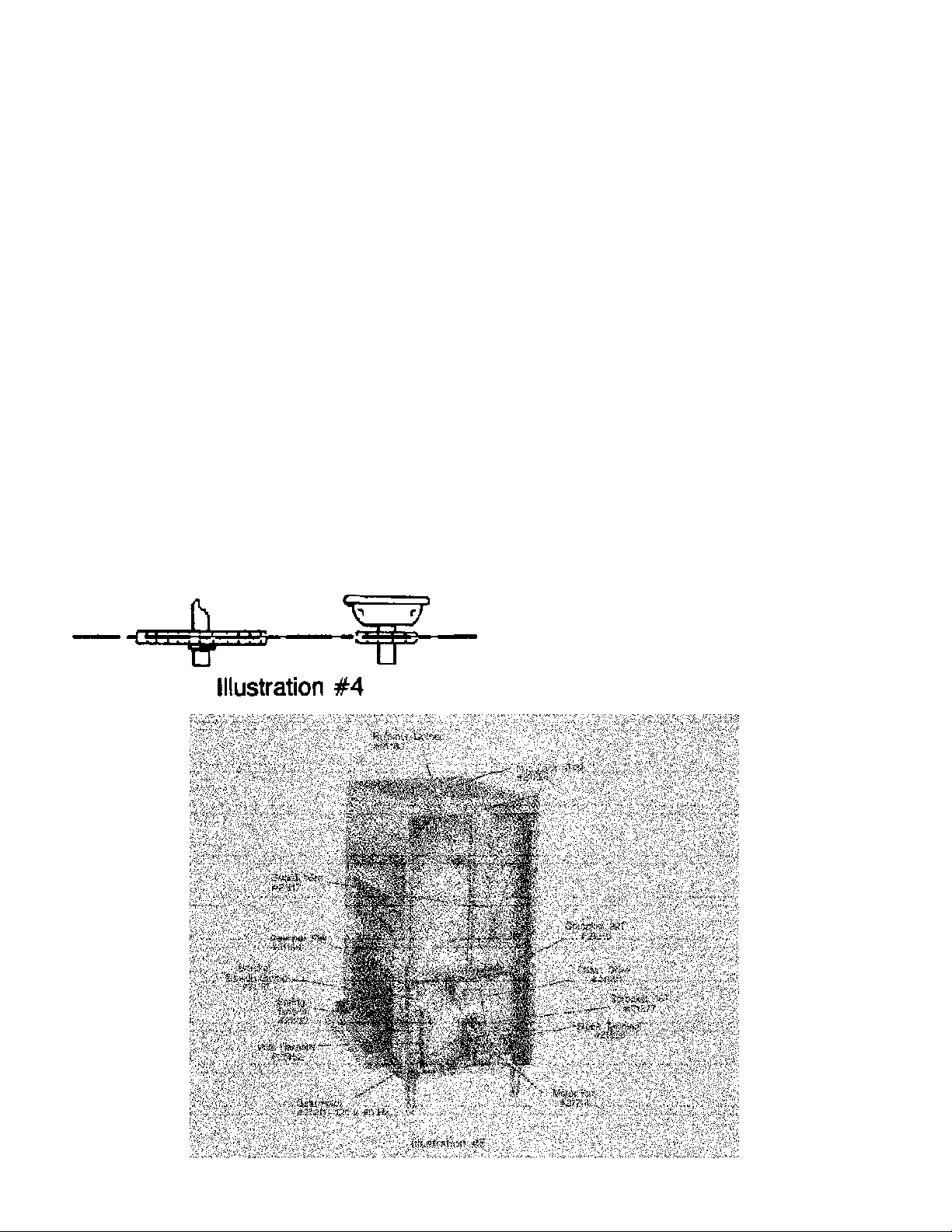
3. Lift off old chain and position new chain over
sprockets. Check orientation. (Illustration 4)
4. Slide motor to right to remove chain slack
and tighten motor mounting bolts.
5. Check chain tension. (Illustration 3) Too
tight will result in premature wear of chain,
sprocket and bearing and may bind drive
components. Too loose will result in chain
slipping or falling off sprockets.
F Clutch Replacement
(Refer to illustration 4 & 5)
1. Remove right side panel.
2. Loosen motor mounting bolts and slide motor to
left and remove drive chain.
3. Loosen Allen screws on clutch sprocket and
remove sprocket from motor shaft.
4. Install new sprocket on motor shaft and tighten
screws. Check sprocket alignment. (Illustration
4)
5. Position chain on sprocket and slide motor to
right to remove slack. Tighten mounting bolts.
Check chain orientation.
6. Check chain tension (Illustration 3) and adjust if
necessary. (See Section D)
7. Replace side panel.
G Hubbed Sprocket Replacement
(Refer to illustration 4 & 5)
1. Remove right side panel.
2. Loosen motor mounting bolts and slide motor left.
3. Remove drive chain and loosen Allen screws on
hub of sprocket and slide off shaft.
4. Install new sprocket and align set screws with
indents in transmission shaft.
5. Replace drive chain and slide motor to right to
tighten. (Illustration 3)
6. Replace side panel.
3

H Bearing Replacement
Coupling Bearing (Right Side)
1. Remove right side panel and insulation.
2. Remove the two lock nuts holding bearing
retainer and remove retainer.
3. Remove old bearing.
4. Install new bearing and seat in opening.
5. Replace retainer, nuts, insulation and side
panel.
Coupling Bearing (Left Side)
1. Remove left side panel and insulation.
2. Remove the two lock nuts holding bearing
retainer and remove retainer.
3. Remove old bearing.
4. Install new bearing and seat in opening.
5. Replace retainer, lock nuts, insulation and side
panel.
Transmission Bearing (Right Side)
1. See Section G; follow steps 1, 2 and 3.
2. Remove the two lock nuts holding bearing
retainer and remove retainer.
3. Remove old bearing.
4. Install new bearing and seat in opening.
5. Replace retainer and lock nuts.
6. See Section G; follow steps 4, 5 and 6.
Transmission Bearing (Left Side)
1. Remove left side panel.
2. Remove the two lock nuts holding bearing
retainer and remove retainer.
3. Remove old bearing.
4. Install new bearing and seat in opening.
5. Replace retainer, nuts and side panel.
I Conveyor Chain Replace-
Tension Assembly Bearing (Right or Left Side)
1. Remove side panel.
2. Remove one end of tension spring from
tension bracket.
3. Remove the two lock nuts holding bearing
retainer and remove retainer.
4. Remove tension bracket and old bearing.
5. Install new bearing and seat in opening.
(Refer to illustration 6)
6. Replace tension bracket, retainer, lock nuts
and spring. NOTE: If tension bracket has
two anchor holes for spring, use hole
closest to the front of machine.
ment
(Refer to illustration 11)
1. Remove toast receiving tray, delivery
chute, left and right side panels.
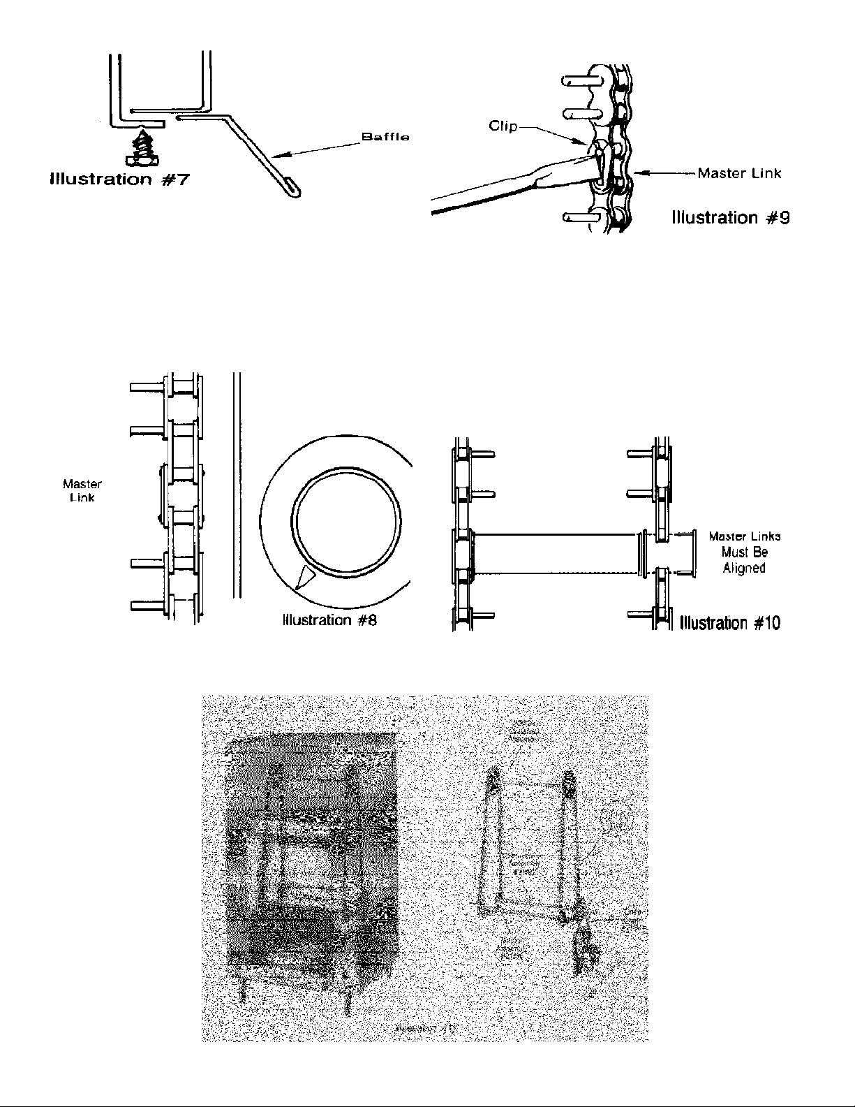
2. Remove the two screws in upper edge of
front opening that holds the front baffle.
Slide baffle toward back of machine to
remove. (Illustration 7)
4
3. Remove baskets by slightly spreading chains, sliding
basket to one side and lifting out.
4. Release the tension spring from spring bracket on both
sides of tension bracket on both sides of tension
assembly.
5. Locate the master link (link without extended pinsillustration 8). Remove clip on master link (Illustration
9) and remove. Pull chain out from bottom.
6. With extended pins facing inward, drape new
chain over the top of the coupling assembly. Make
certain links of chain are meshed over sprocket
teeth. Drop remainder of chain behind sprocket and
from bottom opening, lift it across transmission
assembly and tension assembly sprockets. Visually
check for fit over sprocket teeth and bring two ends
of chain together. Install master link and clip.
Repeat procedure for other chain. IMPORTANT!
Align right and left side master links to insure
proper alignment of baskets. (Illustration 10)
7. Replace baskets, spring on tension brackets, front
baffle, receiving tray, delivery chute and left and
right side panels.
5

J Transmission Assembly Replacement
(Refer to illustration 11)
1. Follow steps 1 thru 5 in Section I.
2. Remove drive chain, hubbed sprocket, bearing retainers and bearings. (Refer to Sections G & H)
3. Slide assembly shaft to right side and lift left end of
shaft out of bearing hole and remove shaft.
4. Inspect shaft bearing for wear or binding. Replace with
new if necessary.
5. Replace new assembly in reverse order.
6. Check conveyor chain line-up. (Refer to Section I Step
6)
7. Check drive chain tension. (Refer to Section E Step 5)
K Tension Assembly Replacement
(Refer to illustration 11)
1. Remove receiving tray, delivery chute, left and right
side panels.
2. Remove all baskets and both conveyor chains. (Refer
to Section I steps 2 thru 5)
3. Unhook tension springs from brackets. (Illustration 6)
4. Remove bearing retainers and bearings.
5. Lift one end of assembly shaft and remove carrier chain
from sprocket. Move chain to one side; repeat for
opposite end of shaft.
6. Slide shaft to one side and lift opposite end out of
bearing hole. Lift assembly out and under to clear
carrier chains.
7. Reverse above procedure to install new assembly.
8. Inspect bearing for wear or binding. Replace with new
if necessary.
9. Install bearing, spring brackets and retainers. Attach
springs to bracket.
10. Check conveyor chain line up. (Illustration 10)
11. Install baskets, left and right side panels.
L Coupling Assembly Replacement
(Refer to illustration 11)
1. Follow steps 1 thru 5, Section I)
2. Remove insulation.
3. Remove wire guard. (Refer to Section M)
4. Locate the four screws on the upper inside corners of
the toaster that hold case top in place. Loosen screws
and lift off top. A rubber mallet or similar “soft” tool
maybe helpful in lifting a tight fitting top. (Illustration 12)
5. Remove insulation.
6. Remove the twelve screws holding the inner top panel
assembly in place and lift it off.
7. Remove coupling assembly bearing from both sides.
(Refer to Section H)
8. Remove the three screws from the left inside panel that
attach to front reflector.
9. Standing at right side of machine gently push on left
inner wall to expand toasting chamber. (Illustration 13)
This will allow enough clearance for coupling assembly
to be lifted from toaster.
6
10. To install new assembly spread inner walls as in
Step 9 for clearance.
11. Check bearing for wear or binding. Replace with
new if necessary.
12. Install bearings, retainers and lock nuts.
13. Replace three screws into front reflector.
14. Replace conveyor chains, springs to tension
brackets, front baffle, inner top assembly, insulation
and case top. Be certain case top is seated properly
in retaining channels.
15. Replace side insulation, wiring, side panels and
baskets.
M Wire Guard Replacement
(Refer to illustration 6)
1. Remove left side panel and insulation.
2. Remove the three nuts holding end plate and
remove plate.
3. Slide out wire guard
4. Insert new wire guard into track. NOTE: Use
rear track for toasting buns or bread. Use
forward track for toasting bread only.
5. Replace end plate, nuts, insulation and side
panel.
N Burner Component Adjustments
1. Air Shutter Adjustments - May be required due to
local gas supply conditions. Loosen air shutter locking
screw on burner. Move shutter until burner flame is
without yellow.
2. Pilot Flame Adjustment - Remove thermostat knob.
With a thin bladed screwdriver, reach through bottom
of opening and turn pilot adjustor screw clockwise until
pilot flame starts to reduce. Then, turn pilot adjuster
screw clockwise until pilot flame starts to reduce.
Then, turn pilot adjustor screw counterclockwise until
pilot flame envelopes and is just above flame switch
sensing tube. Replace thermostat knob. NOTE:
Changing to propane gas will require reducing the
pilot flame to the above condition.
3. Thermostat By-Pass Adjustment - Allow toaster to
reach normal toasting heat. Place bun-toast switch to
the Toast position. Turn thermostat to #1 position (set
on Low with knobs so marked). Carefully remove
thermostat knob without disturbing setting. With a thinbladed screwdriver, reach through upper right of
opening and turn by-pass adjustment screw until
burner flame is steady across length of burner. Replace knob and reset thermostat and bun-toast switch
to original position.
P Radiant Replacement
(Refer to illustration 14)
1. Remove both sides panels.
2. Loosen the inside screws on each corner holding
the case top to the front and rear panels.
3. Lift off top and remove insulation.
4. Remove the three screws from top rear, three
screws from top front, and five screws from each
side and remove inner top cover.
5. Reach through top opening, remove the three
screws holding the radiant retainer strip.
6. Radiants lean inward and can be removed.
7. Place new radiants into the channel retainer with
bosses toward the top and cones facing inward.
8. Place radiant retainer strip over bosses, push
retainer into position and fasten with the three
screws.
9. Place inner top corner in position, fasten with the
five screws from under side of each side, and the
three screws at top rear and top front.
10. Place insulation over inner top cover.
11. Position case top over the four screws and push
to fit toaster.
12. Tighten the four screws to fasten case top of front
and rear panels.
13. Replace side panels.
0 Control Functions
Safety Solenoid Valve - Operates when both flame
switches close, to complete electrical circuit to coil,
which pulls plunger to open gas flow path to front burner
and control solenoid valve.
Pilot Flame Switches - Bulbs, positioned over the
pilots, are heated. Heat is transferred through sensing
tubes to close the series wired switches to complete
circuit and energize the safety solenoid valve coil.
Control Solenoid Valve - Coil is energized by bun-toast
switch placed in TOAST position which pulls plunger to
open gas flow path to the rear burner. In BUN position
coil is not energized, plunger shuts off gas flow.
On/Off Switch -The “ON” position closes the circuit to
the gearmotor, flame switches and bun-toast switch.
Bun-Toast Switch - Completes the electrical circuit to
the control solenoid valve coil when placed in the
TOAST position.
Shut-Off Valve - Manually opens or shuts off gas supply
line. When open, the gas flows through the pilot tubes.
Pressure Regulator - Maintains a 4” water column
pressure when natural gas supply exceeds that pressure.
Thermostat – Regulates the gas flow to the burners.
Gas flow through the thermostat is controlled by the
temperature at the bulb. “Off” position shuts off all gas
flow except through the pilot tubes.
7
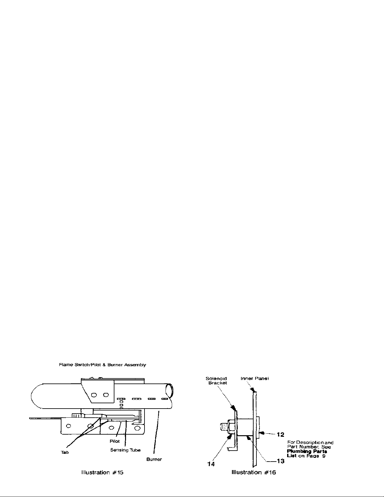
Q Burner Replacement
(Refer to illustration 15 & 17)
1. Loosen nut holding burner lock plate.
2. Remove wires from underside of pilot flame switch.
3. Using a screwdriver, press spring catch on side of
flame switch, snap ceramic base up and out of
bracket.
4. Using a 7/16” open end wrench, loosen pilot tube
compression nut at the burner. CAUTION: Pilot
orifice is loose in end of pilot.
5. Move pilot tube to the side and out of the way.
6. Lift burner to clear orifice and slide burner out.
7. Remove pilot bracket, containing pilot flame switch
assembly by removing screws fastening pilot bracket
to burner.
8. To install new burner, first place pilot bracket,
containing pilot flame switch assembly, on burner
and fasten with retaining screw.
9. Check that pilot flame switch assembly is parallel to
the burner in both the horizontal and vertical plane
and that sensing tube is locked even with the end of
pilot. (Illustration 15)
10. Insert burner into opening, slide along channel until
flat end of burner is fully seated in slot of right interior
wall.
11. Seat burner over orifice.
12. Drop burner lock plate to seat firmly over burner,
tighten nut to secure in place.
13. Place pilot tube in pilot and join by tightening compression nut. CAUTION: Be sure pilot orifice is
positioned in end of pilot.
14. Snap flame switch ceramic into bracket and place
wires on terminals.
R Burner Replacement
(Follow procedures in Section Q)
Sub Assembly Components
(Refer to illustrations 15, 16 & 17)
NOTE: The sub assembly contains the components that
direct and control gas flow to the burners. All threaded
fittings, with the exception of compression fittings and
orifices, should be coated with rectorseal #5 thread
sealing compound during installation.
S Sub Assembly Removal
(Refer to illustration 17)
1. Remove thermostat knob.
2. Remove union on intake pipe.
3. Remove pilot tube compression fittings at pilot flame filter
assembly.
4. Loosen burner lock plate nuts.
5. Bend capillary retainer clamp to achieve clearance and
slip tube from under clamp.
6. Remove wire connections from flame switches and
solenoid valves.
7. Carefully slide thermostat bulb from holder. CAUTION:
Avoid sharp bends or kinks in the capillary tube and
bulb that will create restriction, preventing proper
thermostat operation.
8. Remove the two nuts holding intake pipe to base plate.
9. Remove two nuts from each solenoid bracket, making
sure spacers remain in place. (Illustration 16)
10. Raise burners to clear orifices, tilt top of the sub assembly
to clear solenoid brackets from weld bolts, then move sub
assembly to rear until thermostat shaft clears front of
toaster.
11. Angle front of sub assembly outward and slide out of
toaster.
T Sub Assembly Installation
(Refer to illustration 17)
1. Slip intake pipe through rear opening far enough to allow
thermostat shaft to clear front of toaster and into front
opening.
2. Simultaneously, position solenoid brackets and intake pipe
over weld bolts. (Make sure spacers are in place on the
solenoid brackets). (Illustration 16) Install nuts and
tighten.
3. Carefully insert thermostat bulb into holder, dress capillary
tube and place under clamp. Bend clamp to secure tube.
4. Align burners over orifices, position burner lock plates and
tighten nuts.
5. Attach pilot tubes with compression fittings at pilot flame
filter assembly.
6. Slip wire connections on pilot flame switches and solenoid
valves. (Refer to wiring diagram)
7. Install union between intake pipe and pressure regulator.
8. Replace thermostat knob.
9. Turn on shut-off valve, light pilots and operate toaster.
CHECK ALL CONNECTIONS FOR LEAKS USING
SOAP SOLUTION.
8

9

U Thermostat Replacement
(Refer to illustration 17)
1. Remove sub assembly. (Refer to Section S)
2. Remove the two screws at the top of the thermostat
that go through to hold the intake pipe mounting
flange and remove the intake pipe.
3. Carefully coil the thermostat tube close to the thermostat and safety solenoid.
4. Holding the body of the safety solenoid with a wrench
or vise, unthread thermostat from nipple.
5. To install new thermostat, thread thermostat onto
nipple and tighten. NOTE: If nipple has been
removed with the old thermostat, replace nipple
into safety solenoid. Make sure intake pipe
mounting flange holes are aligned from top to
bottom.
6. Place intake pipe/mounting flange on bottom of
thermostat. Insert the two screws through the top
and secure.
7. Install sub assembly. (Refer to Section T)
V Control Solenoid Valve Replacement
(Refer to illustration 17)
1. Remove sub assembly (Section S), and intake pipe
(Section U Step #2).
2. Remove solenoid plug and retain for new installation.
3. Unthread street elbow assembly.
4. Unthread control solenoid valve from T-fitting, and
remove.
5. Thread new valve onto T-fitting, making sure the
valve is in vertical alignment with the safety solenoid
valve.
6. Thread street elbow assembly to control valve,
making sure street elbow assembly is in vertical
alignment with the other offset pipe.
7. Replace solenoid plug.
8. Replace intake pipe/mounting flange. (Refer to
Section U Step #6)
9. Replace sub assembly. (Refer to Section T)
W Safety Solenoid Valve
Replacement
(Refer to illustration 17)
1. Remove sub assembly (Section S), and
thermostat (Section U).
2. Remove solenoid plug and retain for new
installation.
3. Unthread safety solenoid valve from T-fitting
and remove.
4. To replace, thread safety solenoid valve onto
T-fitting making sure valve is in vertical
alignment with control solenoid valve.
5. Replace solenoid plug.
6. Replace thermostat (Section U), and sub
assembly (Section T).
X Intake Pipe Replacement
(Refer to illustration 17)
1. Remove sub assembly. (Refer to Section S)
2. Remove intake pipe from thermostat. (Refer
to Section U Step #2)
3. Unthreaded intake pipe mounting flange and
remove.
4. Remove pilot flame filter assembly.
5. To install new pipe, replace pilot flame filter
assembly checking for proper alignment.
6. Thread intake pipe mounting flange to intake
pipe, checking for proper orientation.
7. Attach pipe to thermostat. (Refer to Section
U Step #6)
8. Replace sub assembly. (Refer to Section T)
Y Pilot Flame Filter Assembly Replacement
(Refer to illustration 17)
1. Using a 7/16” wrench, remove both compression sleeves.
2. Unthread pilot flame filter assembly from
intake pipe.
3. Reverse this procedure to install new pilot
flame filter assembly.
10
11

1111 N. Hadley Rd.
Fort Wayne, In. 46804
Tel. 800-701-2992
Fax (260) 436-0735 www.mercosavory.com
12
 Loading...