

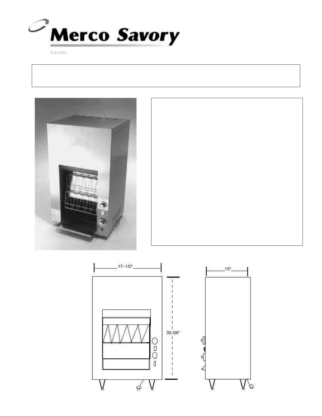
PARTS & SERVICE MANUAL for C-20VS Vertical Conveyor Toaster
The C-20VS is a high volume, vertical conveyor bread
and bun toaster constructed of durable and lustrous
stainless steel. This toaster is available in both 208V and
240V models. 120 V Models are available for shipboard
use only. Refer to the chart on page 7 for parts that
apply exclusively to 120V shipboard toasters.
The C-20VS has a variable conveyor speed control which
allows the toasting of not only bread, but English
muffins, bagels and buns, with only one pass through
the conveyor. Standard features include variable heat,
and bun-toast switch for selecting one or two-sided
toasting.
The C-20VS is engineered for efficient, dependable
service through out the years. Like any piece of fine
equipment with moving parts and broad temperature
ranges, physical wear takes its toll. When this happens,
the information found in this manual will prove very
helpful. Although the instructions are easy to follow, all
repair procedures should be carried out by a qualified
Savory Service Representative.
1200-JDM
07012
CAUTION:
Unplug unit and allow to cool before attempting any
service procedures in this manual.
A On/Off Switch Replacement
1. Remove right side panel. (figures 1 & 2)
2. Remove two retaining screws from front panel.
3. Disconnect wiring harness from switch terminals.
4. Connect wiring harness to new switch and install
switch in panel. Refer to wiring diagram.
B Bun/Toast Switch Replacement
1. Remove right side panel. (Figures 1 & 2)
2. Disconnect wiring harness from switch terminals.
3. Press two spring clips on top of switch and tilt
forward.
4. Insert new switch into panel.
5. Connect wiring harness to new switch.
Refer to wiring diagram.
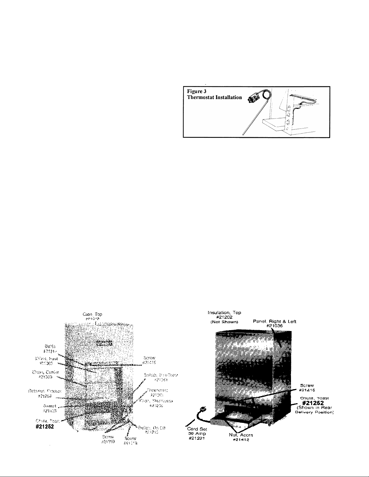
C Thermostat Replacement
1. Remove left and right side panels. (Figures 1 & 2)
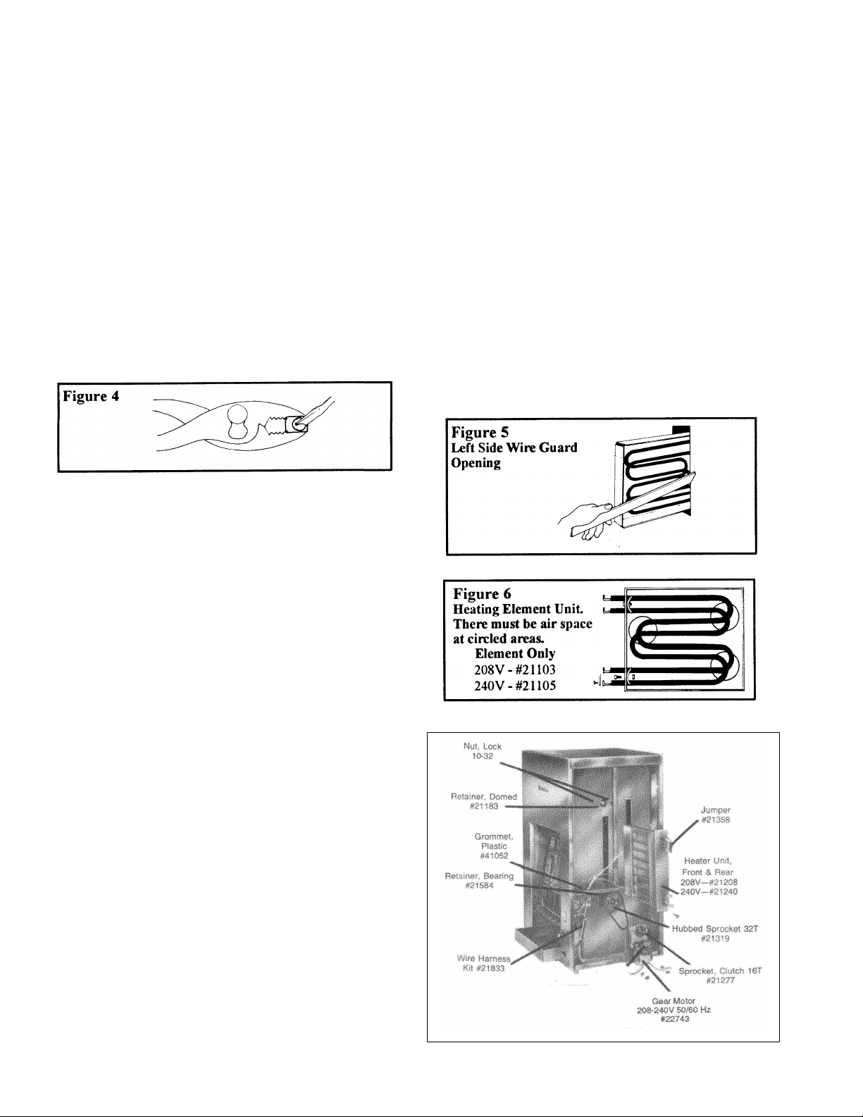
2. Remove insulation. NOTE: The wiring harness must
be disconnected from the heating elements to remove
insulation on the right side. Hold terminals with pliers
to prevent bending. (Figure 4)
3. Remove rear heating element assembly. (Section D)
4. Remove wire guard. (Section O)
5. Remove two baskets from conveyor chain, rotate the
chain so that this opening is at bottom directly under
thermostat bulb.
6. Remove thermostat knob.
7. Remove the two retaining screws from front panel.
8. Remove wires from thermostat.
9. Push as much capillary tube as possible through the plastic
grommet located on the upper portion above the shelf and
pull thermostat bulb out of hole.
10. Feed capillary tube and bulb through plastic grommet into
the lower portion below the shelf and remove.
To Install New Thermostat:
1. Feed bulb and tube through bottom of plastic grommet.
CAUTION: Avoid sharp bends or kinks in the capillary
Tube as this will create restrictions preventing proper
Thermostat operation.
2. Insert bulb into hole and through center guide. The bulb
can be seen through the openings for the wire guard and
rear heater element.
3. Push bulb through hole in left side inner panel. It can be
manually guided by reaching through rear delivery
opening and up through opening in conveyor where
baskets have been removed. Bulb should extend about
1-1/2” from left inner panel.
Figure 1
Figure 2
2
3
14. Attach wires to thermostat. Refer to wiring diagram.
15. Install new thermostat with two screws and replace
knob.
16. Position balance of tube so it runs from bottom of
thermostat along inside of front panel. Coil excess
parallel to and under shelf. Make sure tube is away from
all electrical connections.
17. Replace heater element, wire guard, insulation, heater
wires, and side panel. Refer to wiring diagram.
D Heater Unit Assembly Replacement
1. Remove right side panel. (Figure 7)
2. Holding the heater connections with pliers to prevent
bending, remove three screws holding wiring harness on
heater connections of the unit being replaced. (Figure 4)
F Motor Replacement
1. Remove right side panel.
2. Disconnect lead wire from terminal block and conveyor
speed control (and or P.C. board if contained in your unit).
3. Remove two mounting bolts from under toaster. Slip off
drive chain.
4. Lift out motor and bracket assembly and remove four
screws holding motor to bracket.
5. Using 1/16” Allen wrench, loosen Allen screws and
remove clutch sprocket from motor shaft.
6. Mount clutch sprocket on new motor shaft and mount
new on bracket.
7. Install new motor and bracket assembly attaching with the
two mounting bolts. Do not tighten bolts.
8. Mount drive chain on sprocket by sliding motor to the
left. Slide motor to the right and tighten bolts. (Figure 8)
9. Check sprocket alignment. (Figure 9)
10. Reconnect wire and replace side panel. Refer to wiring
diagram.
3. Remove insulation.
4. Remove the two screws holding heater element to inside
panel.
5. Slide heater unit out the side. NOTE: Because of air
space required in some heating elements, they may not
easily pass through the opening. If element does not slide
out completely, remove left side panel, insulation, and
wire guard. (Section O). Use a suitable flat tool such as
a yardstick or ruler and insert through wire guard opening.
Gently pry heating element at curvature so it can clear
opening and slide out. (figure 5)
6. Slide new heater unit into place and fasten two screws.
7. Replace insulation.
8. Reconnect wiring harness. Refer to wiring diagram.
Hold heater terminals with pliers. Be sure all connections
are tight and jumper has been installed between upper
heater unit connections.
E Individual Heater Element Replacement
Each heater unit is equipped with two elements. These
may be replaced individually as follows:
1. Remove heater unit. (Section D)
2. Place heater unit on a flat surface and remove jumper and
two screws, nuts and retainers.
3. Bend holding tabs away from elements and lift out at an
angle that will let terminal ends clear holes.
4. When replacing elements, make sure element with “raised
bend” on top and “flat” on bottom. There should be air
space at points circled in Figure 6. Elements must not
touch at these points.
Figure 7

G Drive Chain Replacement
1. Remove right side panel.
2. Loosen motor mounting bolts and slide motor to left to
loosen chain.
3. Lift off old chain and position new chain over sprockets.
Check orientation. (Figure 9)
4. Slide motor to right to remove chain slack and tighten
motor mounting bolts.
5. Check chain tension. (Figure 8). Too tight will result in
premature ware of chain, sprocket and bearing and may
bind drive components. Too loose will result in chain
slipping or falling off sprockets.
H Clutch Sprocket Replacements
1. Remove right side panel.
2. Loosen motor mounting bolts and slide motor to left.
Remove drive chain.
3. Loosen Allen screws on clutch sprocket and remove
sprocket from motor shaft.
4. Install new sprocket on motor shaft and tighten screws.
Check sprocket alignment. (Figure 9)
5. Position chain on sprocket and slide motor to right to
remove slack. Tighten mounting bolts. Check chain
orientation, and tension. (Figures 8 & 9). Replace right
side panel.
3. Remove two lock nuts holding bearing retainer and
remove retainer.
4. Remove tension bracket and old bearing.
5. Install new bearing and seat in opening. (Figure 10)
6. Replace tension bracket, retainer, lock nuts and spring.
NOTE: If tension bracket has two anchor holes for
spring, use hole closest to front toaster.
I Hubbed Sprocket Replacement
1. Remove right side panel.
2. Loosen motor mounting bolts and slide motor to left.
3. Remove drive chain and loosen Allen screws on hub of
sprocket and slide off shaft.
4. Install new sprocket and align set screws with indents in
transmission shaft.
5. Replace drive chain and slide motor to right and tighten.
(Figure 8). Replace side panel.
J Bearing Replacement
Coupling Bearing (Right Side)
1. See Section D, follow steps 1,2 and 3.
2. Remove two lock nuts holding bearing retainer and remove
retainer.
3. Remove old bearing.
4. Install new bearing and seat in opening.
5. Replace retainer, nuts, insulation and heater wiring.
Coupling Bearing (Left Side)
1. Remove left side panel and insulation.
2. Remove two lock nuts holding bearing retainer and remove
retainer.
3. Remove old bearing.
4. Install new bearing and seat in opening.
5. Replace retainer and lock nuts.
Tension Assembly Bearing (Right or Left)
1. Remove right side panel.
2. Remove one end of tension spring from tension bracket.
Figure 10

Transmission Bearing (Right Side)
1. See Section I. Follow steps 1,2 and 3.
2. Remove two lock nuts holding bearing retainer and remove
retainer.
3. Remove old bearing.
4. Install new bearing and seat in opening.
5. Replace retainer and lock nuts.
6. See Section I Follow steps 4,5 and 6.
Transmission Bearing (Left side)
1. Remove left side panel.
2. Remove the two lock nuts holding bearing retainer and remove
retainer.
3. Remove old bearing.
4. Install new bearing and seat in opening.
5. Replace retainer, nuts and side panel.
K Conveyor Chain Replacement
1. Remove toast receiving tray, delivery chute, left and right side
panels.
2. Remove the two screws in upper edge of front opening that
hold the front baffle. Slide baffle toward back of machine to
remove. (Figure 11)
3. Remove baskets by slightly spreading chains, sliding basket
to one side and lifting out.
4. Release the tension spring from spring bracket on both sides
of tension bracket on both sides of tension assembly.
5. Locate master link (link without extended pins - (Figure 12).
Remove clips on master link (figure 13) and remove. Pull chain
from bottom.
6. With extended pins facing inward, drape new chain over top of
the coupling assembly. Make sure links of chain are meshed
over sprocket teeth. Drop remainder of chain behind sprocket
and from bottom opening, lift it across transmission assembly
and tension assembly sprockets. Visually check for fit over
sprocket teeth and bring two ends of chain together. Install
master link and clips. Repeat procedure for other chain.
IMPORTANT: Align right and left side master links to insure
proper alignment of baskets. (Figure 14)
7. Replace baskets, spring on tension brackets, front baffle,
receiving tray, delivery chute and left and right side panels.
Figure 12
Master Link
Figure 13
Master Link
Clip

L Transmission Assembly Replacement
1. See Section K. Follow steps 1 through 5.
2. Remove drive chain, hubbed sprocket, bearing retainers and
bearings. (Section I and J)
3. Slide assembly shaft to right side and lift left end of shaft out
of bearing hole and remove shaft.
NOTE: Free-wheeling (left) sprocket is mounted with hub
side inward.
4. Inspect shaft bearing for wear or binding. Replace if
necessary.
5. Replace new assembly in reverse order of above.
6. Check conveyor chain line-up. (section K)
7. Check drive chain tension. (Section G)
M Tension Assembly Replacement
1. Remove receiving tray, delivery chute, left and right side
panels.
2. Remove all baskets and both conveyor chains. (Section K)
3. Unhook tension springs from brackets. (Figure 10)
4. Remove bearing retainers and bearings.
5. Lift one end of assembly shaft and remove carrier chain from
sprocket. Move chain to one side; repeat for opposite end
of shaft.
6. Slide shaft to one side and lift opposite end out of bearing
hole. Lift assembly out and under to clear carrier chains.
7. Reverse above procedure to install new assembly. NOTE:
Free-wheeling (left) sprocket is mounted with hubside
inward.
8. Inspect bearing for wear or binding. Replace if necessary.
9. Install bearing, spring brackets and retainers. Attach springs
to bracket.
10. Check for chain alignment. (Figure 14)
11. Install baskets, left and right side panels.
12. Install bearings, retainers and lock nuts.
13. Replace three screws into front reflector.
14. Replace conveyor chains, springs to tension brackets, front
baffle, inner top assembly, insulation and case top. Be sure
case top is seated properly in retaining channels.
15. Replace side insulation, wiring, side panels and baskets.
Figure 15
N Coupling Assembly Replacement
1. See Section K. Follow steps 1 through 5.
2. Remove insulation. (Section D)
3. Remove wire guard. (Section O)
4. Locate the four screws on the upper inside corners of the
sides that hold the case top in place. (Figure 16). Loosen
screws and top. A rubber mallet or similar “soft” tool may
be helpful with a tight fitting top. (Figure 17)
5. Remove insulation.
6. Remove the twelve screws holding the inner top panel
assembly in place and lift off. (Figure 17)
7. Remove coupling assembly bearing from both sides.
(Section J)
8. Remove the three screws from the left inside panel that
attach to the front reflector. (Circled in Figure 17)
9. Standing at right side of machine, gently push on left inner
wall to expand toasting chamber. (Figure 18). This will
allow enough clearance for coupling assembly to be lifted
from toaster.
10. To install new assembly, spread inner walls as in Step 9 for
clearance.
11. Check bearing for wear or binding. Replace if necessary.

0 Wire Guard Replacement
1. Remove left side panel and insulation.
2. Remove the three nuts holding end plate and remove plate.
(Figure 19)
3. Slide out wire guard.
4. Insert new guard into track.
NOTE: Use rear track for toasting buns or bread. Use
forward track for toasting bread only.
5. Replace end plate, nuts, insulation and side panel.
P P.C. Board Assembly Replacement:
(Refer to Figure 20)
NOTICE: PROCEED WITH THE BELOW LISTED STEPS, ONLY,
IF YOUR UNIT CONTAINS THE P.C. BOARD ASSEMBLY.
1. Remove right side panel.
2. Loosen set screw and remove speed control knob.
3. Remove nut securing potentiometer.
4. Disconnect wires from P.C. Board and remove screws, nuts
and washers holding guard to toaster frame.
5. Remove board and potentiometer.
6. Install new board assembly reversing above procedure.
Figure 20

PARTS FOR C-20VS, 120V MODELS
8
(For Shipboard Use ONLY)
DESCRIPTION PART #
Heater Unit, Front & Back 21120
Heater Element Only 21101
P.C. Board Assembly 12464
Cordset 21231
Gear Motor 22742
Leg, 4” Metal Adjustable 41142
Wiring Diagram C-20VS
1111 N. Hadley Rd.
Fort Wayne, In. 46804
Tel. 800-701-2992
Fax (260) 436-0735 www.mercosavory.com
 Loading...