

SAVIN Aficio SP5200S, SP5200S, SP5200S, Aficio SP 5200SHW*, Aficio SP 5200SHT* Service Manual
...Page 1

M052/M053/M054
SERVICE MANUAL
Page 2

It is the reader's responsibility when discussing the information contained
within this document to maintain a level of confidentiality that is in the best
interest of Ricoh Americas Corporation and its member companies.
NO PART OF THIS DOCUMENT MAY BE REPRODUCED IN ANY
F ASHION AND DISTRIBUTED WITHOUT THE PRIOR
PERMISSION OF RICOH AMERICAS CORPORATION.
All product names, domain names or product illustrations, including
desktop images, used in this document are trademarks, registered
trademarks or the property of their respective companies.
They are used throughout this book in an informational or editorial fashion
only and for the benefit of such companies. No such use, or the use of
any trade name, or web site is intended to convey endorsement or other
affiliation with Ricoh products.
© 2011 RICOH Americas Corporation. All rights reserved.
Page 3

The Service Manual contains information
regarding service techniques, procedures,
processes and spare parts of office equipment
distributed by Ricoh Americas Corporation.
Users of this manual should be either service
trained or certified by successfully completing a
Ricoh Technical Training Program.
Untrained and uncertified users utilizing
information contained in this service manual to
repair or modify Ricoh equipment risk personal
injury, damage to property or loss of warranty
protection.
Ricoh Americas Corporation
WARNING
Page 4
LEGEND
PRODUCT
CODE
COMPANY
LANIER RICOH SAVIN
M052
SP5200S
SP 5200SHW*
SP 5200SHT*
Aficio SP5200S
Aficio SP 5200SHW*
Aficio SP 5200SHT*
SP5200S
SP 5200SHW*
SP 5200SHT*
M053
SP5210SF
SP 5210SFHW*
SP 5210SFHT*
Aficio SP5210SF
Aficio SP 5210SFHW*
Aficio SP 5210SFHT*
SP5210SF
SP 5210SFHW*
SP 5210SFHT*
M054 SP5210SR Aficio SP5210SR SP5210SR
*HC (Healthcare models)
DOCUMENTATION HISTORY
REV. NO. DATE COMMENTS
*
11/2011 Original Printing
Page 5

SM i M052/M053/M054
M052/M053/M054
TABLE OF CONTENTS
1. PRODUCT INFORMATION .......................................................... 1-1
1.1SPECIFICATIONS ..................................................................................... 1-1
1.2OVERVIEW ................................................................................................ 1-2
1.2.1 MECHANICAL COMPONENT LAYOUT ........................................... 1-2
1.2.2 DRIVE LAYOUT ............................................................................... 1-3
1.2.3 PAPER PATH ................................................................................... 1-4
Standard Model (M052)/ Fax and 1 Bin Tray Unit Model (M053) ......... 1-4
Finisher Model (M054) ......................................................................... 1-5
1.3MACHINE CONFIGURATION ................................................................... 1-6
1.3.1 MACHINE CONFIGURATION .......................................................... 1-6
Controller Devices ................................................................................ 1-8
2. INSTALLATION ............................................................................ 2-1
2.1INSTALLATION REQUIREMENTS ............................................................ 2-1
2.1.1 ENVIRONMENT ............................................................................... 2-1
2.1.2 MACHINE LEVEL ............................................................................. 2-1
2.1.3 MINIMUM OPERATIONAL SPACE REQUIREMENTS .................... 2-2
2.1.4 POWER REQUIREMENTS .............................................................. 2-2
2.2OPTIONAL UNIT COMBINATIONS ........................................................... 2-3
2.2.1 MACHINE OPTIONS ........................................................................ 2-3
Fax Options .......................................................................................... 2-3
2.2.2 CONTROLLER AND OTHER OPTIONS .......................................... 2-4
Controller Options ................................................................................ 2-4
Other Options ....................................................................................... 2-4
2.3COPIER ..................................................................................................... 2-5
2.3.1 ACCESSORY CHECK ...................................................................... 2-5
2.3.2 INSTALLATION PROCEDURE ........................................................ 2-6
Copier settings ..................................................................................... 2-6
Fax Settings only for M053 model ........................................................ 2-9
When Using an Smart Card Reader ..................................................... 2-9
2.3.3 METER CLICK CHARGE ............................................................... 2-11
2.4PAPER FEED UNIT TK1090 (M375) ....................................................... 2-13
2.4.1 INSTALLATION PROCEDURE ...................................................... 2-13
Page 6

M052/M053/M054 ii SM
2.5 PAPER FEED UNIT TK1100 (M376) ....................................................... 2-15
2.5.1 INSTALLATION PROCEDURE ...................................................... 2-15
When installing the three units (M375 and M376) .............................. 2-17
2.6 FAX OPTION TYPE SP5200 (M381) ....................................................... 2-18
2.6.1 COMPONENT CHECK ................................................................... 2-18
2.6.2 INSTALLATION PROCEDURE ...................................................... 2-19
2.7 COPY DATA SECURITY UNIT TYPE F (B829) ....................................... 2-23
2.7.1 COMPONENTS CHECK ................................................................. 2-23
2.7.2 INSTALLATION .............................................................................. 2-24
User Tool Setting ............................................................................... 2-25
2.8 CONTROLLER OPTIONS ....................................................................... 2-26
2.8.1 OVERVIEW .................................................................................... 2-26
SD Card Slots .................................................................................... 2-26
I/F Card Slot ....................................................................................... 2-26
USB Slots ........................................................................................... 2-26
2.8.2 SD CARD APPLI MOVE ................................................................. 2-27
Overview ............................................................................................ 2-27
Move Exec ......................................................................................... 2-28
Undo Exec .......................................................................................... 2-29
2.8.3 FILE FORMAT CONVERTER (D377) ............................................. 2-30
Installation Procedure ........................................................................ 2-30
2.8.4 IEEE 802.11 A/G, G (D377: WIRELESS LAN) ............................... 2-31
Installation Procedure ........................................................................ 2-31
UP Mode Settings for Wireless LAN .................................................. 2-33
SP Mode and UP Mode Settings for IEEE 802.11 a/g, g Wireless LAN2-35
2.8.5 BLUETOOTH INTERFACE UNIT TYPE D (D566) ......................... 2-36
Installation Procedure ........................................................................ 2-36
2.8.6 BROWSER UNIT TYPE E (D430) .................................................. 2-37
Installation Procedure ........................................................................ 2-37
Update Procedure .............................................................................. 2-38
2.8.7 GIGABIT ETHERNET BOARD TYPE A (G874)/ TYPE C (M397) .. 2-39
Installation Procedure ........................................................................ 2-39
2.8.8 IPDS UNIT TYPE 5210 (D571) ....................................................... 2-40
Installation Procedure ........................................................................ 2-40
2.8.9 MEMORY UNIT TYPE B 32MB (G578) .......................................... 2-41
2.8.10 CHECK ALL CONNECTIONS .................................................... 2-41
2.9 OPTIONAL COUNTER UNIT INTERFACE TYPE A ....................... 2-42
2.10 DATA OVERWRITE SECURITY UNIT TYPE I (D362) 2-45
Page 7

SM iii M052/M053/M054
3. PREVENTIVE MAINTENANCE .................................................... 3-1
3.1MAINTENANCE TABLES .......................................................................... 3-1
3.1.1 USER MAINTENANCE ..................................................................... 3-1
3.1.2 SERVICE MAINTENANCE ............................................................... 3-1
3.2PM PARTS SETTINGS .............................................................................. 3-2
3.2.1 BEFORE REMOVING THE OLD PM PARTS ................................... 3-2
3.2.2 AFTER INSTALLING THE NEW PM PARTS ................................... 3-2
3.2.3 OPERATION CHECK ....................................................................... 3-2
4. REPLACEMENT AND ADJUSTMENT ........................................ 4-1
4.1PRECAUTIONS ......................................................................................... 4-1
4.1.1 GENERAL ......................................................................................... 4-1
AIO ....................................................................................................... 4-1
Transfer Roller ..................................................................................... 4-1
Scanner Unit ........................................................................................ 4-1
Laser Unit ............................................................................................. 4-2
Fusing Unit ........................................................................................... 4-2
Paper Feed .......................................................................................... 4-2
4.1.2 LITHIUM BATTERIES ....................................................................... 4-2
4.1.3 HALOGEN-FREE CABLE ................................................................. 4-2
4.2SPECIAL TOOLS AND LUBRICANTS ...................................................... 4-3
4.3ADJUSTING COPY IM AGE AREA ............................................................ 4-4
4.3.1 PRINTING ......................................................................................... 4-4
Adjusting Registration .......................................................................... 4-4
Adjusting Blank Margin......................................................................... 4-6
Adjusting Main-Scan Magnification ...................................................... 4-7
4.3.2 SCANNING ....................................................................................... 4-7
Adjusting Registration .......................................................................... 4-7
Adjusting Magnification ........................................................................ 4-8
4.3.3 DF IMAGE ADJUSTMENT ............................................................... 4-9
4.4EXTERIOR COVERS .............................................................................. 4-11
4.4.1 LEFT COVER ................................................................................. 4-11
4.4.2 RIGHT COVER ............................................................................... 4-12
4.4.3 REAR LOWER COVER .................................................................. 4-13
4.4.4 FRONT DOOR ................................................................................ 4-14
4.4.5 DUPLEX UNIT ................................................................................ 4-15
4.4.6 OPERATION PANEL UNIT ............................................................. 4-16
Operation Panel Unit .......................................................................... 4-16
Key Tops ............................................................................................ 4-18
Page 8

M052/M053/M054 iv SM
4.4.7 TOUCH PANEL POSITION ADJUSTMENT ................................... 4-20
4.4.8 OUTPUT TRAY (M052/M053 MODELS ONLY) ............................. 4-21
4.5SCANNER UNIT ...................................................................................... 4-22
4.5.1 SCANNER FRONT COVER ........................................................... 4-22
4.5.2 SCANNER RIGHT AND LEFT COVERS ........................................ 4-23
Scanner Right Cover .......................................................................... 4-23
Scanner Left Cover ............................................................................ 4-23
4.5.3 SCANNER REAR COVER .............................................................. 4-24
4.5.4 EXPOSURE GLASS ....................................................................... 4-25
When reassembling the ARDF exposure glass .................................. 4-25
4.5.5 LED BOARD ................................................................................... 4-26
4.5.6 SCANNER MOTOR ........................................................................ 4-29
4.5.7 SENSOR BOARD UNIT (SBU) ....................................................... 4-30
When reassembling ........................................................................... 4-30
4.5.8 LED DRIVE BOARD ....................................................................... 4-31
4.5.9 SCANNER HP SENSOR ................................................................ 4-32
4.5.10 COVER SENSOR ....................................................................... 4-33
4.5.11 FRONT SCANNER WIRE........................................................... 4-34
Reinstalling the Front Scanner Wire ................................................... 4-35
4.5.12 REAR SCANNER WIRE ............................................................. 4-38
Reinstalling the Rear Scanner Wire ................................................... 4-39
4.6LASER OPTI CS ....................................................................................... 4-40
4.6.1 CAUTION DECAL LOCATIONS ..................................................... 4-40
4.6.2 SAFETY SWITCHES FOR LASER UNIT ....................................... 4-41
4.6.3 LASER UNIT ................................................................................... 4-41
Preparation before Removing the Laser Unit ..................................... 4-41
Removing the Laser Unit for All Models ............................................. 4-42
4.6.4 POLYGON MOTOR ........................................................................ 4-43
4.6.5 LASER SYNCHRONIZATION DETECTOR .................................... 4-44
4.7PAPER TRANSF ER ................................................................................ 4-45
4.7.1 TRANSFER ROLLER ..................................................................... 4-45
4.8DRIVE SECTION ..................................................................................... 4-46
4.8.1 GEARBOX ...................................................................................... 4-46
4.8.2 MAIN MOTOR ................................................................................ 4-47
4.8.3 DUPLEX MOTOR ........................................................................... 4-48
4.8.4 BY-PASS FEED CLUTCH .............................................................. 4-49
4.8.5 RELAY CLUTCH ............................................................................ 4-49
4.8.6 PAPER FEED CLUTCH .................................................................. 4-50
Page 9

SM v M052/M053/M054
4.8.7 REGISTRATION CLUTCH ............................................................. 4-50
4.9PAPER FEED .......................................................................................... 4-51
4.9.1 PAPER FEED ROLLER .................................................................. 4-51
4.9.2 FRICTION PAD .............................................................................. 4-52
When reassembling the friction pad ................................................... 4-52
4.9.3 PAPER END SENSOR ................................................................... 4-53
4.9.4 REMAINING PAPER SENSORS .................................................... 4-53
4.9.5 REGISTRATION SENSOR ............................................................. 4-54
4.9.6 BY-PASS PAPER SENSOR ........................................................... 4-54
4.9.7 DUPLEX RELAY SENSOR ............................................................. 4-55
When reassembling the duplex relay sensor ...................................... 4-55
4.9.8 JUNCTION GATE 1 SOLENOID .................................................... 4-56
4.9.9 JUNCTION GATE 2 SOLENOID .................................................... 4-57
4.9.10 FUSING EXIT SENSOR (M053 MODEL ONLY) ........................ 4-58
4.9.11 PAPER OVERFLOW SENSOR (M052/M053 MODELS ONLY) . 4-58
4.10 FUSING .............................................................................................. 4-59
4.10.1 FUSING UNIT ............................................................................. 4-59
4.10.2 HOT ROLLER AND PRESSURE ROLLER SECTIONS ............. 4-60
4.10.3 FUSING LAMP ........................................................................... 4-61
4.10.4 HOT ROLLER ............................................................................. 4-62
4.10.5 FUSING THERMISTOR ............................................................. 4-63
4.10.6 THERMOSTATS ......................................................................... 4-63
4.10.7 PRESSURE ROLLER ................................................................. 4-64
4.10.8 FUSING CLEANING ROLLER .................................................... 4-64
4.11 DUPLEX UNIT ................................................................................... 4-65
4.11.1 DUPLEX UNIT ............................................................................ 4-65
4.11.2 DUPLEX INVERTER MOTOR .................................................... 4-66
4.11.3 DUPLEX EXHAUST FAN ........................................................... 4-67
4.11.4 DUPLEX INVERTER SENSOR .................................................. 4-69
4.11.5 DUPLEX ENTRANCE SENSOR ................................................. 4-70
4.12 ELECTRICAL COMPONENTS .......................................................... 4-71
4.12.1 CONTROLLER UNIT .................................................................. 4-71
4.12.2 HDD UNIT ................................................................................... 4-72
4.12.3 HDD CONTROL BOARD ............................................................ 4-73
4.12.4 NVRAM ....................................................................................... 4-73
When reinstalling a new NVRAM ....................................................... 4-74
4.12.5 EEPROMS .................................................................................. 4-76
When reinstalling a new EEPROM ..................................................... 4-76
Page 10

M052/M053/M054 vi SM
4.12.6 DIMM RAM ................................................................................. 4-77
4.12.7 CONTROLLER BOARD ............................................................. 4-78
When installing a new controller board............................................... 4-79
4.12.8 BICU ........................................................................................... 4-80
BICU................................................................................................... 4-80
BICU Bracket ..................................................................................... 4-81
4.12.9 HVPS (HIGH VOLTAGE POWER SUPPLY) .............................. 4-83
4.12.10 RFID BOARD ............................................................................ 4-83
4.12.11 TONER END SENSOR ............................................................ 4-84
4.12.12 PAPER SIZE SENSOR BOARD ............................................... 4-84
4.12.13 PSU .......................................................................................... 4-85
4.13 ARDF ................................................................................................. 4-87
4.13.1 ARDF .......................................................................................... 4-87
When installing the Platen Sheet ....................................................... 4-88
4.13.2 ARDF REAR COVER ................................................................. 4-88
4.13.3 ARDF FRONT COVER AND ORIGINAL TRAY .......................... 4-89
4.13.4 ORIGINAL FEED UNIT ............................................................... 4-90
4.13.5 PICK-UP ROLLER ...................................................................... 4-91
4.13.6 FEED ROLLER ........................................................................... 4-92
4.13.7 ARDF FRICTION PAD ................................................................ 4-93
4.13.8 ARDF DRIVE BOARD ................................................................ 4-94
4.13.9 ORIGINAL SET SENSOR AND ARDF TOP COVER SENSOR . 4-95
4.13.10 ARDF FEED MOTOR ............................................................... 4-97
4.13.11 ARDF FEED CLUTCH .............................................................. 4-98
4.13.12 ARDF TRANSPORT MOTOR ................................................... 4-99
4.13.13 ARDF REGISTRATION SENSOR .......................................... 4-101
4.13.14 ARDF INVERTER SENSOR ................................................... 4-102
4.13.15 ARDF COOLING FAN ............................................................ 4-103
When installing the cooling fan ......................................................... 4-103
4.14 INTERNAL FINISHER ...................................................................... 4-104
4.14.1 INTERNAL FINISHER .............................................................. 4-104
When reinstalling the internal finisher .............................................. 4-105
4.14.2 FINISHER OUTPUT TRAY UNIT ............................................. 4-106
4.14.3 STAPLER UNIT ........................................................................ 4-107
4.14.4 GATHERING ROLLER MOTOR ............................................... 4-108
4.14.5 FINISHER PAPER EXIT MOTOR ............................................. 4-109
4.14.6 SHIFT ROLLER MOTOR .......................................................... 4-110
4.14.7 FINISHER TRANSPORT MOTOR ............................................ 4-111
Page 11

SM vii M052/M053/M054
4.14.8 TRAY LIFT MOTOR ................................................................. 4-112
4.14.9 JOGGER FENCE HP SENSOR ............................................... 4-113
4.14.10 JOGGER MOTOR .................................................................. 4-115
4.14.11 EXIT GUIDE PLATE MOTOR ................................................. 4-116
4.14.12 SHIFT ROLLER HP SENSOR ................................................ 4-117
4.14.13 GATHERING ROLLER HP SENSOR ..................................... 4-118
4.14.14 FINISHER ENTRANCE SENSOR .......................................... 4-119
4.14.15 FINISHER EXIT SENSOR ...................................................... 4-120
4.14.16 FINISHER PAPER SENSOR .................................................. 4-122
4.14.17 STAPLE TRAY PAPER SENSOR .......................................... 4-123
4.14.18 TRAY LOWER LIMIT SENSOR .............................................. 4-124
4.14.19 EXIT GUIDE PLATE HP SENSOR ......................................... 4-124
4.14.20 FINISHER MAIN BOARD ....................................................... 4-125
When reinstalling a new finisher main board .................................... 4-125
4.15 1 BIN TRAY UNIT ............................................................................ 4-126
4.15.1 1 BIN TRAY UNIT ..................................................................... 4-126
4.15.2 1 BIN TRAY PAPER EXIT SENSOR ........................................ 4-130
4.15.3 1 BIN TRAY PAPER SENSOR AND LED BOARD ................... 4-131
5. SYSTEM MAINTENANCE REFERENCE ..................................... 5-1
5.1SERVICE PROGRAM ................................................................................ 5-1
5.1.1 USING SP AND SSP MODES .......................................................... 5-1
5.1.2 TYPES OF SP MODES .................................................................... 5-1
SP Mode Button Summary ................................................................... 5-2
Switching Between SP Mode and Copy Mode for Test Printing ........... 5-3
Selecting the Program Number ............................................................ 5-3
Exiting Service Mode............................................................................ 5-4
Service Mode Lock/Unlock ................................................................... 5-4
5.1.3 REMARKS ........................................................................................ 5-5
Display on the Control Panel Screen ................................................... 5-5
Others .................................................................................................. 5-6
5.2SYSTEM SP1-XXX .................................................................................... 5-7
5.2.1 SP1-XXX (FEED) .............................................................................. 5-7
5.3SYSTEM SP2-XXX .................................................................................. 5-13
5.3.1 SP2-XXX (DRUM)........................................................................... 5-13
5.4SYSTEM SP3-XXX .................................................................................. 5-15
5.4.1 SP3-XXX (PROCESS) .................................................................... 5-15
5.5SYSTEM SP4-XXX .................................................................................. 5-16
5.5.1 SP4-XXX (SCANNER) .................................................................... 5-16
Page 12

M052/M053/M054 viii SM
5.6SYSTEM SP5-XXX .................................................................................. 5-34
5.6.1 SP5-XXX (MODE) .......................................................................... 5-34
5.7SYSTEM SP6-XXX ................................................................................ 5-102
5.7.1 SP6-XXX (PERIPHERALS) .......................................................... 5-102
5.8SYSTEM SP7-XXX ................................................................................ 5-105
5.8.1 SP7-XXX (DATA LOG) ................................................................. 5-105
5.9SYSTEM SP8-XXX ................................................................................ 5-116
5.9.1 SP8-XXX: DATA LOG2 ................................................................. 5-116
5.10 INPUT AND OUTPUT CHECK ......................................................... 5-164
5.10.1 INPUT CHECK TABLE ............................................................. 5-164
Mianframe ........................................................................................ 5-164
ARDF ............................................................................................... 5-168
Internal Finisher ............................................................................... 5-169
5.10.2 OUTPUT CHECK TABLE ......................................................... 5-170
Copier ............................................................................................... 5-170
ARDF ............................................................................................... 5-172
Internal Finisher ............................................................................... 5-173
5.11 PRINTER SERVICE MODE ............................................................. 5-174
5.11.1 SP1-XXX (SERVICE MODE) .................................................... 5-174
5.12 SCANNER SERVICE MODE ........................................................... 5-183
5.12.1 SP1-XXX (SYSTEM AND OTHERS) ........................................ 5-183
5.12.2 SP2-XXX (SCANNING-IMAGE QUALITY) ............................... 5-185
5.13 FAX SERVICE MODE ...................................................................... 5-186
5.14 FIRMWARE UPDATE ...................................................................... 5-187
5.14.1 TYPE OF FIRMWARE .............................................................. 5-187
5.14.2 BEFORE YOU BEGIN .............................................................. 5-189
5.14.3 UPDATING FIRMWARE ........................................................... 5-190
Preparation ....................................................................................... 5-190
Updating Procedure ......................................................................... 5-190
Error Messages ................................................................................ 5-191
Firmware Update Error ..................................................................... 5-191
Recovery after Power Loss .............................................................. 5-192
5.14.4 UPDATE PROCEDURE FOR APP2ME PROVIDER ................ 5-193
5.14.5 BROWSER UNIT UPDATE PROCEDURE ............................... 5-194
5.14.6 HANDLING FIRMWARE UPDATE ERRORS ........................... 5-195
Error Message Table ........................................................................ 5-195
5.15 SD CARD APPLI MOVE .................................................................. 5-197
5.15.1 OVERVIEW .............................................................................. 5-197
Page 13

SM ix M052/M053/M054
Outline of SD Card Appli Move: ....................................................... 5-197
5.15.2 MOVE EXEC ............................................................................ 5-198
5.15.3 UNDO EXEC ............................................................................ 5-199
5.16 NVRAM DATA UPLOAD/DOWNLOAD ............................................ 5-200
5.16.1 UPLOADING CONTENT OF NVRAM TO AN SD CARD ......... 5-200
5.16.2 DOWNLOADING AN SD CARD TO NVRAM ........................... 5-201
5.17 CARD SAVE FUNCTION ................................................................. 5-202
5.17.1 OVERVIEW .............................................................................. 5-202
Card Save: ....................................................................................... 5-202
5.17.2 PROCEDURE ........................................................................... 5-203
5.17.3 ERROR MESSAGES ................................................................ 5-205
5.18 USING SP MODES .......................................................................... 5-206
5.18.1 ADJUSTING REGISTRATION AND MAGNIFICATION ............ 5-206
5.18.2 TEST PATTERN PRINT (SP 5902) .......................................... 5-206
Executing Test Pattern Printing ........................................................ 5-206
Test Patterns .................................................................................... 5-206
5.18.3 SMC PRINT (SP 5990) ............................................................. 5-208
5.18.4 HOW TO READ THE AIO S/N (SP 5793-011) .......................... 5-208
6. TROUBLESHOOTING ................................................................. 6-1
6.1SERVICE CALL CONDITIONS .................................................................. 6-1
6.1.1 SUMMARY ....................................................................................... 6-1
6.1.2 SC CODE DESCRIPTIONS .............................................................. 6-2
SC1xx: Scanning .................................................................................. 6-3
SC2xx: Laser Exposure ........................................................................ 6-6
SC3xx: Image Processing – 1 .............................................................. 6-8
SC4xx: Image Processing - 2 ............................................................... 6-8
SC5xx: Paper Feed and Fusing ........................................................... 6-9
SC6xx: Device Communication .......................................................... 6-12
SC7xx: Peripherals ............................................................................ 6-17
SC8xx: Controller ............................................................................... 6-20
SC9xx: Others .................................................................................... 6-28
6.2ELECTRICAL COMPONENT DEFECTS ................................................. 6-32
6.2.1 BLOWN FUSE CONDITIONS ......................................................... 6-32
Power Supply Unit .............................................................................. 6-32
6.3JAM DETECTION .................................................................................... 6-33
6.3.1 PAPER JAM DISPLAY ................................................................... 6-33
6.3.2 JAM CODES AND DISPLAY CODES ............................................. 6-33
Page 14

M052/M053/M054 x SM
Paper Jam Detection Sensor Location ............................................... 6-39
7. ENERGY SAVING ........................................................................ 7-1
7.1ENERGY SAVE ......................................................................................... 7-1
7.1.1 ENERGY SAVER MODES ............................................................... 7-1
Timer Settings ...................................................................................... 7-1
Return to Stand-by Mode ..................................................................... 7-2
Recommendation ................................................................................. 7-2
7.1.2 ENERGY SAVE EFFECTIVENESS .................................................. 7-2
7.2PAPER SAVE ............................................................................................ 7-4
7.2.1 EFFECTIVENESS OF DUPLEX/COMBINE FUNCTION .................. 7-4
1. Duplex: ............................................................................................. 7-4
2. Combine mode: ................................................................................ 7-4
3. Duplex + Combine: ........................................................................... 7-4
How to calculate the paper reduction ratio ........................................... 7-5
M052/M053/M054 SERVICE MANUAL APPENDICES
SEE M052/M053/M054 SERVICE MANUAL APPENDICES SECTION FOR DETAILED TABLE
OF CONTENTS
FAX OPTION TYPE SP5200 (M381)
SEE M381 SECTION FOR DETAILED TABLE OF CONTENTS
PAPER FEED UNIT TK1090/TK1100/TK1120/TK1130
(M375/M376/M386/M389)
SEE M375/M376/M386/M389 SECTION FOR DETAILED TABLE OF CONTENTS
Page 15

Page 16

READ THIS FIRST
Safety Notices
Important Safety Notices
Prevention of Physical Injury
1. Before disassembling or assembling parts of the machine and peripherals, make sure that
the machine power cord is unplugged.
2. The wall outlet should be near the machine and easily accessible.
3. If any adjustment or operation check has to be made with exterior covers off or open while
the main switch is turned on, keep hands away from electrified or mechanically driven
components.
4. The machine drives some of its components when it completes the warm-up period. Be
careful to keep hands away from the mechanical and electrical components as the machine
starts operation.
5. The inside and the metal parts of the fusing unit become extremely hot while the machine is
operating. Be careful to avoid touching those components with your bare hands.
Health Safety Conditions
Toner is non-toxic, but if you get either of them in your eyes by accident, it may cause temporary
eye discomfort. Try to remove with eye drops or flush with water as first aid. If unsuccessful, get
medical attention.
Observance of Electrical Safety Standards
The machine and its peripherals must be serviced by a customer service representative who
has completed the training course on those models.
The Controller board on this machine contains a lithium battery. The danger of explosion
exists if a battery of this type is incorrectly replaced. Replace only with the same or an
equivalent type recommended by the manufacturer. Discard batteries in accordance with
the manufacturer's instructions and local regulations.
The optional fax and memory expansion units contain lithium batteries, which can explode
if replaced incorrectly. Replace only with the same or an equivalent type recommended by
the manufacturer. Do not recharge or burn the batteries. Used batteries must be handled in
accordance with local regulations.
Page 17

Safety and Ecological Notes for Disposal
1. Do not incinerate toner bottles or used toner. Toner dust may ignite suddenly when
exposed to an open flame.
2. Dispose of used toner, the maintenance unit which includes developer or the organic
photoconductor in accordance with local regulations. (These are non-toxic supplies.)
3. Dispose of replaced parts in accordance with local regulations.
To prevent a fire or explosion, keep the machine away from flammable liquids, gases,
and aerosols. A fire or an explosion might occur.
Lithium Batteries
Incorrect replacement of lithium battery(s) on the FCU, controller board and memory board unit
may pose risk of explosion. Replace only with the same type or with an equivalent type
recommended by the manufacturer. Discard used batteries in accordance with the
manufacturer's instructions.
Laser Safety
The Center for Devices and Radiological Health (CDRH) prohibits the repair of laser-based
optical units in the field. The optical housing unit can only be repaired in a factory or at a
location with the requisite equipment. The laser subsystem is replaceable in the field by a
qualified Customer Engineer. The laser chassis is not repairable in the field. Customer
engineers are therefore directed to return all chassis and laser subsystems to the factory or
service depot when replacement of the optical subsystem is required.
Use of controls, or adjustment, or performance of procedures other than those
specified in this manual may result in hazardous radiation exposure.
Page 18
WARNING
WARNING:
Turn off the main switch before attempting any of the procedures in the Laser Optics
Housing Unit section. Laser beams can seriously damage your eyes.
CAUTION MARKING:
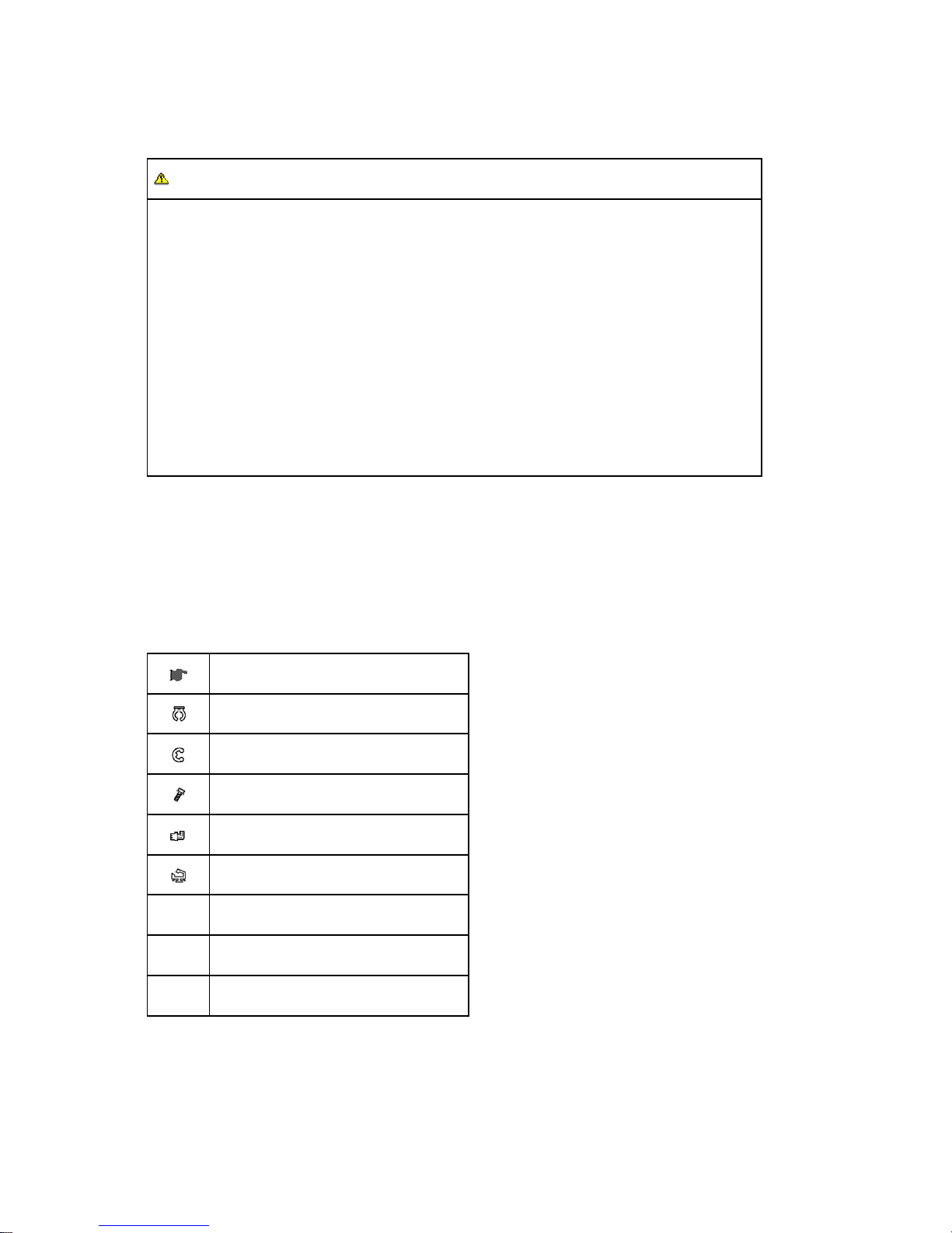
Symbols and Abbreviations
This manual uses several symbols and abbreviations. The meaning of those symbols and
abbreviations is as follows:
See or Refer to
Clip ring
E-ring
Screw
Connector
Clamp
SEF Short Edge Feed
LEF Long Edge Feed
- Core Technology manual
Page 19
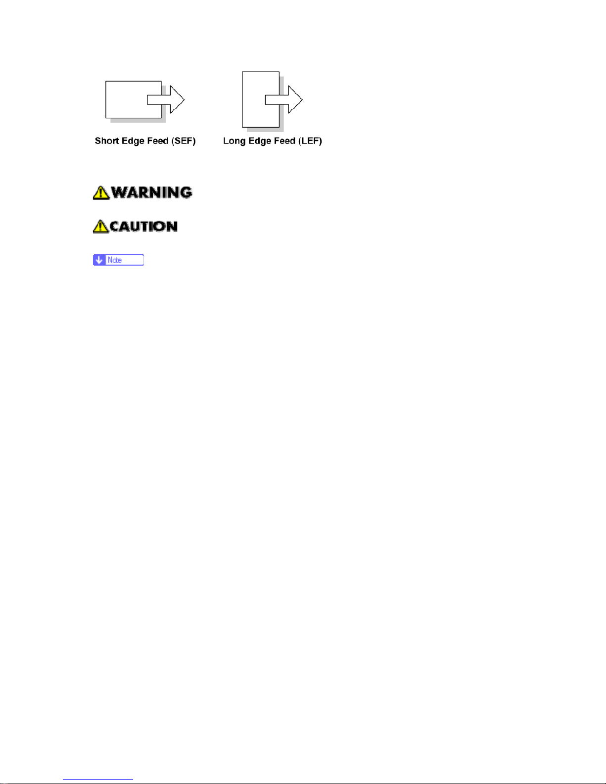
Cautions, Notes, etc.
The following headings provide special information:
Failure to obey warning information could result in serious injury or death.
Obey these guidelines to ensure safe operation and prevent minor injuries.
This information provides tips and advice about how to best service the machine.
Page 20

PRODUCT INFORMATION
REVISION HISTORY
Page Date Added/Updated/New
None
Page 21

Page 22

Specifications
SM 1-1 M052/M053/M054
Product
Information
1. PRODUCT INFORMATION
1.1 SPECIFICATIONS
See "Appendices" for the following information:
General Specifications
Supported Paper Sizes
Page 23

Overview
M052/M053/M054 1-2 SM
1.2 OVERVIEW
1.2.1 MECHANICAL COMPONENT LAYOUT
1. Scanner unit
2. Laser unit
3. Charge roller
4. Cartridge (AIO-type)
5. Drum
6. Development roller
7. By-pass feed tray
8. By-pass feed roller
9. Paper feed roller
10. Friction pad
11. Paper tray
12. Registration roller
13. Transfer roller
14. Pressure roller
15. Hot roller
16. Junction gate 1*
1
17. Paper exit roller*
2
18. Junction gate 2*
3
19. Inverter roller
*
1
: Junction gate 1 is not movable for the finisher model (M054).
*
2
: Paper exit roller is not used for the finisher model (M054).
*
3
: Junction gate 2 is not movable for the standard model (M052).
Page 24

Overview
SM 1-3 M052/M053/M054
Product
Information
1.2.2 DRIVE LAYOUT
1. Registration clutch
2. Relay clutch
3. By-pass clutch
4. Paper feed clutch
5. Main motor
6. Duplex motor
7. Inverter motor
Page 25

Overview
M052/M053/M054 1-4 SM
1.2.3 PAPER PATH
Standard Model (M052)/ Fax and 1 Bin Tray Unit Model (M053)
1. Paper feed from tray 1
2. Paper feed from by-pass tray
3. Paper feed from optional PFU (tray2)
4. Paper feed from optional PFU (tray3)
5. Paper feed from optional PFU (tray4)
6. Paper feed through duplex unit
7. Paper exit to 1 bin tray (M053 only)
Page 26

Overview
SM 1-5 M052/M053/M054
Product
Information
Finisher Model (M054)
1. Paper feed from tray 1
2. Paper feed from by-pass tray
3. Paper feed from optional PFU (tray2)
4. Paper feed from optional PFU (tray3)
5. Paper feed from optional PFU (tray4)
6. Paper feed through duplex unit
7. Paper exit to internal finisher (M054 only)
Page 27
Machine Configuration
M052/M053/M054 1-6 SM
1.3 MACHINE CONFIGURATION
1.3.1 MACHINE CONFIGURATION
M052 M053 M054
Fax Unit Option Standard Option
1 Bin Tray Unit Not available Standard Not available
Internal Finisher Not available Not available Standard
Page 28

Machine Configuration
SM 1-7 M052/M053/M054
Product
Information
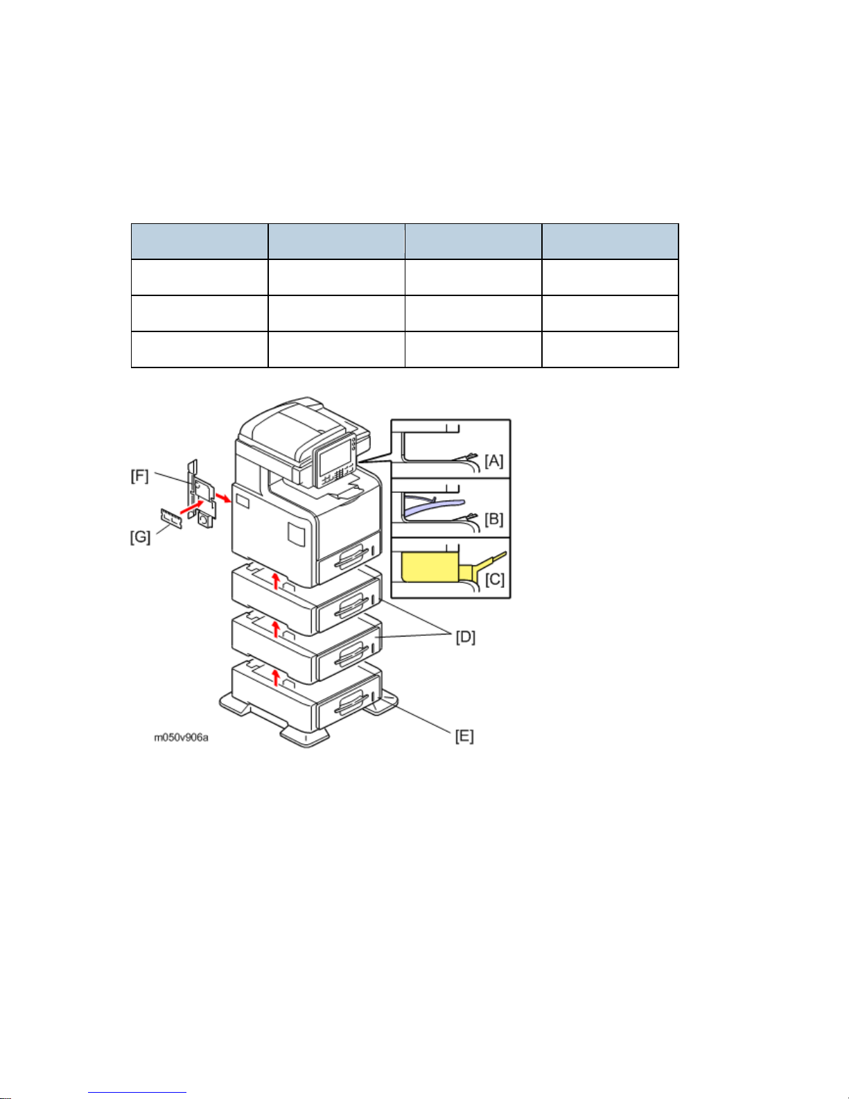
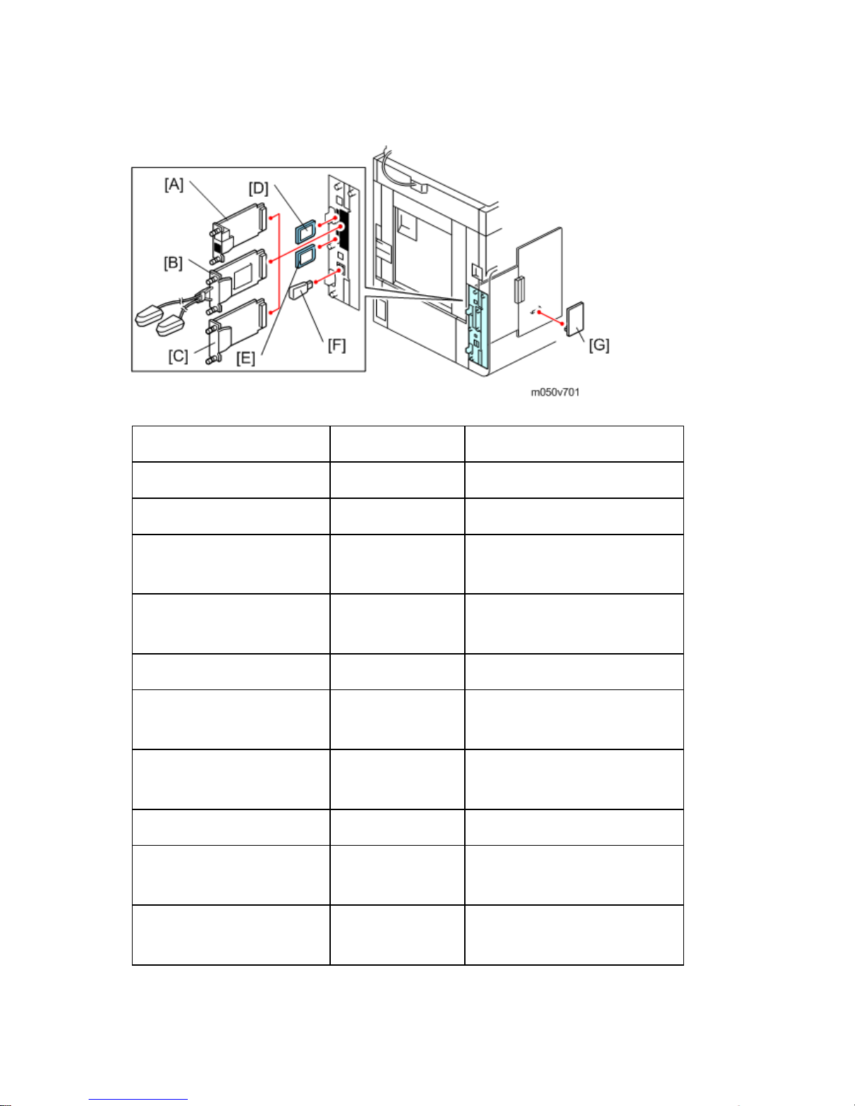
Item Machine Code Remarks
Main Unit [A] M052 Standard model
Main Unit [B] M053 Fax and 1 bin tray unit model
Main Unit [C] M054 Finisher model
Paper Feed Unit TK1090 [D] M375 Option
Paper Feed Unit TK1100 [E] M376 Option
Fax Option Type SP5200 [F] M381
Standard for M053
Option for M052 and M054
Memory Unit Type B [G] G578
SAF memory:
Requires the Fax Option.
Page 29
Machine Configuration
M052/M053/M054 1-8 SM
Controller Devices
Item Machine Code Remarks
VM Card [E] - Standard
Security Card [D] - Standard
Copy Data Security Unit Type
F [G]
B829 Option
Remote Communication Gate
A
D459 Option
IPDS Unit Type 5210 [D] D571 Controller Option
Gigabit Ethernet Board Type
A/ Type C [A]
Type A: G874
Type C: M397
Controller Option
IEEE802.11 a/g Interface Unit
Type J, K [B]
D377 Controller Option
Browser Unit Type E [E] D430 Controller Option
File Format Converter Type E
[C]
D377 Controller Option
Bluetooth Interface Unit Type
D [F]
D566 Controller Option
Page 30

INSTALLATION
REVISION HISTORY
Page Date Added/Updated/New
1 1 ~ 12 12/26/2012 Meter click charge
22 5/16/2012 Fax installation
42 ~ 44 12/27/2011 Optional Counter Unit Interface Type A
45 ~ 50 1 1/7/20 13 Data Overwrite Security Unit Type I (D362)
Page 31

Page 32

Installation Requirements
SM 2-1 M052/M053/M054
Installation
2. INSTALLATION
2.1 INSTALLATION REQUIREMENTS
2.1.1 ENVIRONMENT
–Temperature and Humidity Chart–
Temperature Range: 10°C to 32°C (50°F to 89.6°F)
Humidity Range: 15% to 80% RH
Ambient Illumination: Less than 1,500 lux (Do not expose to direct sunlight.)
Ventilation: Room air should turn over at least 3 times/hr/person
Ambient Dust: Less than 0.1 mg/m
3
Do not install the machine where it will be exposed to direct sunlight or to direct airflow
(from a fan, air conditioner, air cleaner, etc.).
Do not install the machine where it will be exposed to corrosive gas.
Install the machine at locations lower than 2,000 m (6,560 ft.) above sea level.
Place the machine on a firm and level base.
Do not install the machine where it may be subjected to strong vibration.
2.1.2 MACHINE LEVEL
Front to back: Within 5 mm (0.2") of level
Right to left: Within 5 mm (0.2") of level
Page 33

Installation Requirements
M052/M053/M054 2-2 SM
2.1.3 MINIMUM OPERATIONAL SPACE REQUIREMENTS
Place the machine near the power source, providing clearance as shown.
A: Front – 350 mm (29.6")
B: Left – 100 mm (3.9")
C: Rear – 300 mm (3.9")
D: Right – 100 mm (3.9")
2.1.4 POWER REQUIREMENTS
Make sure that the wall outlet is near the machine and easily accessible. After
completing installation, make sure the plug fits firmly into the outlet.
Avoid multiple connections to the same power outlet.
Be sure to ground the machine.
Input voltage:
North America: 120 – 127 V, 60 Hz, 12 A
Europe/Asia: 220 – 240 V, 50/60 Hz, 8 A
Image quality guaranteed at rated voltage ± 10%.
Operation guaranteed at rated voltage ± 15%.
Page 34

Optional Unit Combinations
SM 2-3 M052/M053/M054
Installation
2.2 OPTIONAL UNIT COMBINATIONS
2.2.1 MACHINE OPTIONS
No. Options Remarks
1 Paper Feed Unit TK1090
Two units can be installed in the
mainframe.
2 Paper Feed Unit TK1100 This unit has casters.
Fax Options
No. Options Remarks
3 Fax Option Type SP5200
Standard for M053
Options for M052/M054
4 Memory Unit Type B
SAF memory:
Requires the fax option.
Page 35

Optional Unit Combinations
M052/M053/M054 2-4 SM
2.2.2 CONTROLLER AND OTHER OPTIONS
Controller Options
No. Options Remarks
1 IPDS Unit Type 5210 SD slot 1 (upper)
2 Browser Unit Type E
SD slot 2 (lower) during
installation only
3 Bluetooth Interface Unit Type D One of USB slots
4 Gigabit Ethernet Board Type A/ Type C
IF slot (one from three
options)
5 IEEE802.11 a/g Interface Unit Type J, K
6 File Format Converter Type E
Other Options
No. Options Remarks
7 Copy Data Security Unit Type F -
- Remote Communication Gate A -
Page 36

Copier
SM 2-5 M052/M053/M054
Installation
2.3 COPIER
2.3.1 ACCESSORY CHECK
Description Q’ty
AIO 1
Power Cord 1
VM Card 1
Extender (finisher support tray; M054 only) 1
Paper Size and Tray Decals 1
Warranty Sheet (NA only) 1
User Registration Card (NA only) 1
Help Desk Card (NA only) 1
EULA (16 languages) 1
Page 37

Copier
M052/M053/M054 2-6 SM
2.3.2 INSTALLATION PROCEDURE
Make sure that the copier remains unplugged during installation.
Copier settings
1. Remove the plastic bag.
2. Lift the machine by the inset grips on its sides.
At least four people are needed to lift the machine.
3. Lower the machine slowly and carefully to prevent trapping your hands.
4. Remove the adhesive tape attached on the machine's exterior.
5. Only for M054 model, do the following steps from 1) and 2).
1) Pull out tray 1 [A], and then remove the extender [B] for the internal finisher from tray
1.
Page 38

Copier
SM 2-7 M052/M053/M054
Installation
2) Attach the extender [A] to the finisher tray.
6. Lift the ARDF [A], and then remove the protective materials attached on the exposure
glass.
7. Close the ARDF.
8. Open the front door [A] pressing the button.
9. Remove the AIO [B], and then remove the protective material attached on the machine's
interior.
10. Install the AIO into the machine.
11. Close the front door.
Page 39

Copier
M052/M053/M054 2-8 SM
12. Remove the SD slot cover [A] ( x 1).
13. Install the VM card [B] provided in the accessories in the SD slot 2 (lower).
14. Attach the SD slot cover [A] (
x 1).
15. Plug in the machine, and then turn on the machine.
16. Start the SP mode.
17. Select SP5-302-002 and specify the time zone.
18. Select SP5-307-001, 003, and 004 and specify the daylight-saving-time settings.
19. Exit the SP mode and turn the main switch off and on.
20. Start the UP mode.
21. Specify the date and time with "Set Date" or "Set Time" (User Tool" > "System Settings" >
"Set Date" or "Set Time").
22. Turn the main switch off and on.
23. Check the operations.
24. Make a full size copy, and check if the side-to-side and leading edge registrations are
correct. If they are not, adjust the registrations.
Page 40

Copier
SM 2-9 M052/M053/M054
Installation
Fax Settings only for M053 model
Initializing the Fax unit
When you press the Fax key for the first time after installation, the error "SRAM problem
occurred / SRAM was formatted" will show on the LCD for initializing the program of the fax unit.
Turn the main power switch off/on to clear the error display.
If another error occurs after initialization, this can be a functional problem.
1. Select fax SP1-101-016 and specify the country code.
2. Select fax SP3-101-001 and specify the service station.
When Using an Smart Card Reader
If a customer wants to use a smart card reader, follow the installation procedure below. The
smart card reader must be placed on the specific place. If not, some antenna or transmitter in
the main machine may be interrupted.
1. ARDF rear cover (
p.4-88)
2. Attach the smart card reader [A].
1. Release the hook, and then put the cable outside.
Page 41

Copier
M052/M053/M054 2-10 SM
2. Route the cable [A] as shown above.
3. Remove the part [A] of the ARDF rear cover with nippers or a similar tool.
4. Reassemble the machine.
5. For details about connecting a smart card device to the machine, refer to the installation
procedure provided with the smart card device.
Page 42

Copier
SM 2-11 M052/M053/M054
Installation
2.3.3 METER CLICK CHARGE
Basically, there are two ways to set up this function.
Meter click charge enabled (SP 5-930-001 set to "enabled") and Parts replacement
operation type enabled (SP5-067-001 set to "0: Service"): The counter can be displayed and
printed by the customer. The technician can then call the customer and ask them to read the
counter.
Meter click charge disabled (SP 5-930-001 set to "disabled"; this is the default setting)
and Parts replacement operation type enabled (SP5-067-001 set to "1: User", this is the
default setting): The counter cannot be displayed or printed by the customer. To check the
counter, the technician must print the SMC report (SP 5-990).
You must select one of the counter methods (developments/prints) in accordance with
the contract by using SP5-045-001.
Item SP No. Function Default
Meter Click
Charge Setting
SP5-930-001
Enables or disables Meter Click
Charge.
When enabled:
The counter menu shows
immediately after you push the
"Menu" key. The "Counter
Method" (SP5-045) sets the
type of the counter.
You can print the counter from
the counter menu.
When disabled:
The counter menu does not
show.
"0": OFF
Meter Click
Charge: Life
Disp:
Maintenance Kit
SP5-930-002
Enables or disables the PM alert for
the maintenance kit.
If this SP is enabled, an alert
message is displayed when the
maintenance kit needs to be
replaced.
"0": Off
⇒
Rev. 12/26/2012
Page 43

INSTALLATION
REVISION HISTORY
Page Date Added/Updated/New
1 1 ~ 12 12/26/2012 Meter click charge
22 5/16/2012 Fax installation
42 ~ 44 12/27/2011 Optional Counter Unit Interface Type A
Page 44

Paper Feed Unit TK1090 (M375)
SM 2-13 M052/M053/M054
Installation
2.4 PAPER FEED UNIT TK1090 (M375)
2.4.1 INSTALLATION PROCEDURE
Unplug the main machine's power cord before starting the following procedure.
The number of optional paper feed units that can be attached depends on the location where
the machine is installed.
[A]: Only one paper feed unit (M375 [D]) can be installed on a desk.
[B]: Up to three units (M375 [D] and M376 [E]) can be installed on the floor. Attach the
optional paper feed unit with casters (M376 [E]) to the bottom of the machine to install the
machine directly on the floor.
[C]: Attach the optional paper feed unit with casters (M376 [E]) to the bottom of the machine
to install the machine directly on the floor.
Page 45

Paper Feed Unit TK1090 (M375)
M052/M053/M054 2-14 SM
1. Remove all tapes and cardboard on the paper feed unit [A].
2. Pull the paper tray part way out of the paper feed unit, remove the tape and cardboard in
the paper tray, and push the tray back in.
3. Set the machine [A] on the paper feed unit [B].
Two people are required to lift the machine.
When installing a second paper feed unit, place on the first paper feed unit before
placing the copier onto the pair of paper feed units
4. Remove the paper(s) tray from the paper tray unit(s).
5. Load paper into the paper tray(s). Adjust the side and end fences as necessary. If loading
8
1
/2"x 14" paper, remove the end fence and set it into the special compartment.
6. Set the paper tray(s) back into the paper tray unit(s).
Page 46

Paper Feed Unit TK1100 (M376)
SM 2-15 M052/M053/M054
Installation
2.5 PAPER FEED UNIT TK1100 (M376)
2.5.1 INSTALLATION PROCEDURE
Unplug the main machine's power cord before starting the following procedure.
The number of optional paper feed units that can be attached depends on the location where
the machine is installed.
[A]: Only one paper feed unit (M375 [D]) can be installed on a desk.
[B]: Up to three units (M375 [D] and M376 [E]) can be installed on the floor. Attach the
optional paper feed unit with casters (M376 [E]) to the bottom of the machine to install the
machine directly on the floor.
[C]: Attach the optional paper feed unit with casters (M376 [E]) to the bottom of the machine
to install the machine directly on the floor.
Page 47

Paper Feed Unit TK1100 (M376)
M052/M053/M054 2-16 SM
1. Remove all tapes and cardboard on the paper feed unit [A].
2. Pull the paper tray part way out of the paper feed unit, remove the tape and cardboard in
the paper tray, and push the tray back in.
3. Set the machine [A] on the paper feed unit [B].
Two people are required to lift the machine.
When installing a second paper feed unit, place on the first paper feed unit before
placing the copier onto the pair of paper feed units
4. Remove the paper(s) tray from the paper tray unit(s).
5. Load paper into the paper tray(s). Adjust the side and end fences as necessary. If loading
8
1
/2"x 14" paper, remove the end fence and set it into the special compartment.
6. Set the paper tray(s) back into the paper tray unit(s).
Page 48

Paper Feed Unit TK1100 (M376)
SM 2-17 M052/M053/M054
Installation
When installing the three units (M375 and M376)
1. Attach the six brackets and six screws as shown above.
2. Attach the screws into the paper feed units as shown above.
Page 49

Fax Option Type SP5200 (M381)
M052/M053/M054 2-18 SM
2.6 FAX OPTION TYPE SP5200 (M381)
2.6.1 COMPONENT CHECK
Check the quantity and condition of the components against the following list.
No. Description Q’ty
1 FCU 1
2 Fax Key top 2
3 G3 Decal 1
4 Serial Number Decal 1
5 FCC Decal (NA only) 1
6 Multi-Language Decals (EU only) 1
7 Ferrite Core 1 (Excluding NA)
8 Telephone Cord (NA only) 1
- EMC Address Card (EU only) 1
Page 50

Fax Option Type SP5200 (M381)
SM 2-19 M052/M053/M054
Installation
2.6.2 INSTALLATION PROCEDURE
Before installing this fax unit:
Print out all data in the printer buffer.
Turn off the main power switch and disconnect the power cord and the network cable.
1. Remove the FCU slot cover [A] (
x 3).
2. Switch the MBU battery jumper switch [A] to “ON” position.
Page 51

Fax Option Type SP5200 (M381)
M052/M053/M054 2-20 SM
3. Press down the place [A] on the MBU board.
4. Install the FCU [A] into the FCU slot [B] of the machine.
Align the top edge [C] of the FCU board with the rail [D] in the FCU slot when installing
the FCU.
5. Secure the FCU [A] (
x 3).
Use two screws which have already been removed in step 1.
6. Attach the serial number decal on the area [B] of the FCU bracket and FCC decal (NA only)
on the area [C] above the serial number decal of the machine.
7. Connect the telephone cord to the "LINE" jack.
Page 52

Fax Option Type SP5200 (M381)
SM 2-21 M052/M053/M054
Installation
For EU/AA, attach the ferrite core to the telephone cord before connecting the
telephone cord to the "LINE" jack.
For NA, use the core attached telephone cord (No.9) in the accessories of the fax unit
option.
8. Attach an appropriate multi-language decal [A] (EU only).
9. Replace the blank key [B] with the fax key [C].
10. Attach the decal [A] (SUPER G3) to the front door.
11. Put the power plug into the outlet and turn on the main power of the machine.
Page 53

Fax Option Type SP5200 (M381)
M052/M053/M054 2-22 SM
Make sure that the outlet is grounded.
"SRAM formatted" shows on the operation panel after you have turned the main
switch on. Turn the main switch off and on again for normal use.
12. Enter the "User Tools" mode and set date and time.
13. Enter SP3-102 in the fax SP mode and enter the serial number for the fax unit.
14. Enter the correct country code with UP mode (NCU Country/ Area Code Setting).
15. Exit the SP mode, and turn the machine off and on.
⇒
⇒
Rev. 05/16/2012
Page 54

Copy Data Security Unit Type F (B829)
SM 2-23 M052/M053/M054
Installation
2.7 COPY DATA SECURITY UNIT TYPE F (B829)
2.7.1 COMPONENTS CHECK
No. Description Q’ty
1 ICIB-3 1
2 Flexible cable: Long (Not used) 1
3 Flexible cable: Short (Not used) 1
4 Harness with bands (Not used) 1
5 Harness (Not used) 1
6 Saddle Clamp (Not used) 1
7 Screws: M3x6 6
8 Bracket (Not used) 1
Page 55

Copy Data Security Unit Type F (B829)
M052/M053/M054 2-24 SM
2.7.2 INSTALLATION
Unplug the main machine power cord before you do the following procedure.
1. Open the front door.
2. Pull out the tray 1 [A].
3. Remove the left cover [A] of the machine ( x 3).
4. Move the scanner I/F cable aside [A] (
x 1, x 2).
5. Move the harness guide [B] aside (
x 3).
Page 56

Copy Data Security Unit Type F (B829)
SM 2-25 M052/M053/M054
Installation
6. Attach ICIB-3 [A] to CN107 [B] on the BICU (
x 1).
7. Reassemble the machine.
User Tool Setting
1. Plug in the machine and turn on the main power switch.
2. Go into the User Tools mode, and select System Settings > Administrator Tools > Copy
Data Security Option > “On”.
3. Exit User Tools.
4. Check the operation.
The machine will issue an SC165 error if the machine is powered on with the
ICIB-3 removed and the “Data Security for Copying“ feature set to “ON”.
The machine will issue an uncertain SC165 error if ICIB-3 is defective when the
machine is powered on and the “Data Security for Copying“ feature is set to “OFF”.
When you remove this option from the machine, first set this feature to “OFF” with
the user tool before removing this board. If you forget to do this, “Data Security for
Copying “feature cannot appear in the user tool setting. Also, SC165 will appear
every time the machine is switched on, and the machine cannot be used.
5. Make sure that the machine can recognize the option.
Page 57

Controller Options
M052/M053/M054 2-26 SM
2.8 CONTROLLER OPTIONS
2.8.1 OVERVIEW
This machine has I/F card slots for optional I/F connections and SD card slot applications.
After you install an option, check that the machine can recognize it (see “Check All
Connections” at the end of this section).
SD Card Slots
Slot 1 (upper slot) [A] is used for Security Card (standard) or IPDS Unit.
If IPDS Unit is to be installed, first merge IPDS application into the Security Card with SP
mode.
Slot 2 (lower slot) [B] is used for VM card (standard) or service only (for example, updating
the firmware).
I/F Card Slot
The I/F card slot [C] is used for one of the optional I/F connections (only one can be
installed): Gigabit Ethernet, IEEE802.11a/g (Wireless LAN), or File Format Converter.
USB Slots
Both USB slots [D] are used for the Bluetooth option and a card authentication device.
Page 58

Controller Options
SM 2-27 M052/M053/M054
Installation
2.8.2 SD CARD APPLI MOVE
The PostScript3 application and fonts cannot be moved to another SD card. However,
other applications can be moved onto the PostScript3 SD card.
Overview
The service program “SD Card Appli Move” (SP5-873) lets you copy application programs from
one SD card to another SD card.
SD slot 1 (upper ) is used to store application programs. But there are two possible applications
(Security Card (Data Overwrite Security and HDD Encryption Unit), IPDS). You cannot run
application programs from Slot 2. However you can move application programs from SD slot 2
(lower slot) to SD slot 1 (upper slot) with the following procedure.
Make sure that the target SD card has enough space.
1. Enter SP5873 “SD Card Appli Move”.
2. Then move the application from the SD Card in SD slot 2 (lower slot) to the SD Card in SD
slot 1 (upper slot).
Do steps 1-2 again if you want to move another application program.
3. Exit the SP mode.
Be very careful when you do the SD Card Appli Move procedure:
The data necessary for authentication is transferred with the application program from an
SD card to another SD card. Authentication fails if you try to use the SD card af ter you copy
the application program from one card to another card.
Do not use the SD card if it has been used before for other purposes. Normal operation is
not guaranteed when such an SD card is used.
Keep the SD card in a safe place after you copy the application program from one card to
another card. This is done for the following reasons:
1) The SD card can be the only proof that the user is licensed to use the application
program.
2) You may need to check the SD card and its data to solve a problem in the future.
Page 59

Controller Options
M052/M053/M054 2-28 SM
Move Exec
The menu “Move Exec” (SP5-873-001) lets you copy application programs from the original SD
card to another SD card.
Do not turn ON the write protect switch of the system SD card or application SD card
on the machine. If the write protect switch is ON, a download error (e.g. Error Code 44)
occurs during a firmware upgrade or application merge.
1. Turn the main switch off.
2. Make sure that an SD card is in SD slot 1 (upper slot). The application program is copied to
this SD card.
3. Insert the SD card with the application program in SD slot 2 (lower slot). The application
program is copied from this SD card.
4. Turn the main switch on.
5. Start the SP mode.
6. Select SP5-873-001 "Move Exec".
7. Follow the messages shown on the operation panel.
8. Turn the main switch off.
9. Remove the SD card from SD slot 2 (lower slot).
10. Turn the main switch on.
11. Check that the application programs run normally.
Page 60

Controller Options
SM 2-29 M052/M053/M054
Installation
Undo Exec
“Undo Exec” (SP5-873-002) lets you copy back application programs from an SD card to the
original SD card. You can use this program when, for example, you have mistakenly copied
some programs by using Move Exec (SP5-873-001).
Do not turn ON the write protect switch of the system SD card or application SD card
on the machine. If the write protect switch is ON, a download error (e.g. Error Code 44)
occurs during a firmware upgrade or application merge.
1. Turn the main switch off.
2. Insert the original SD card in SD slot 2 (lower slot). The application program is copied back
into this card.
3. Insert the SD card with the application program in SD slot 1 (upper slot). The application
program is copied back from this SD card.
4. Turn the main switch on.
5. Start the SP mode.
6. Select SP5-873-002 “Undo Exec.”
7. Follow the messages shown on the operation panel.
8. Turn the main switch off.
9. Remove the SD card from SD slot 2 (lower slot).
This step assumes that the application programs in the SD card are used by the
machine.
10. Turn the main switch on.
11. Check that the application programs run normally.
12. Make sure that the machine can recognize the option (see ‘Check All Connections’ at the
end of this section).
Page 61

Controller Options
M052/M053/M054 2-30 SM
2.8.3 FILE FORMAT CONVERTER (D377)
Installation Procedure
Unplug the main machine power cord before you do the following procedure.
You can only install one of the following network interfaces or printer enhanced option at one
time: (IEEE 802.11 a/g, g (Wireless LAN), Gigabit Ethernet, or File Format Converter).
1. Remove the I/F-slot cover [A] (
x 2).
2. Install the file format converter [A] into the I/F-slot and then fasten it with screws.
3. Plug in and turn on the main power switch.
4. Check or set the following SP codes with the values shown below.
Page 62

Controller Options
SM 2-31 M052/M053/M054
Installation
SP No. Title Setting
SP5-836-001 Capture Function (0:Off 1:On) "1"
SP5-836-002 Panel Setting "0"
5. Check the operation.
6. Make sure that the machine can recognize the option (see ‘Check All Connections’ at the
end of this section).
2.8.4 IEEE 802.11 A/G, G (D377: WIRELESS LAN)
Installation Procedure
Unplug the main machine power cord before you do the following procedure.
You can only install one of the following network interfaces or printer enhanced option at one
time: (IEEE 802.11 a/g, g (Wireless LAN), Gigabit Ethernet, or File Format Converter).
1. Remove the I/F-slot cover [A] from the I/F-slot (
x 2).
2. Install the wireless LAN board [A] (Knob-screw x 2) into the I/F-slot.
3. Make sure that the machine can recognize the option (see ‘Check All Connections’ at the
Page 63

Controller Options
M052/M053/M054 2-32 SM
end of this section).
4. Peel off the cover from the double-sided tape on the Velcro fasteners [A], and then attach
the fasteners [A] at the scanner left cover of the machine.
5. Attach the antennas [B] to the fasteners on the scanner left cover.
6. Attach eight clamps as shown above.
7. Wire the cables and clamp them (
x 8).
Make sure that the cables are not slack. Keep them wired tightly along the covers.
You may have to move the machine if the reception is not clear.
Make sure that the machine is not located near an appliance or any type of equipment that
generates strong magnetic fields.
Put the machine as close as possible to the access point.
Page 64

Controller Options
SM 2-33 M052/M053/M054
Installation
UP Mode Settings for Wireless LAN
Enter the UP mode. Then do the procedure below to perform the initial interface settings for
IEEE 802.11 a/g, g. These settings take effect every time the machine is powered on.
You cannot use the wireless LAN if you use Ethernet.
1. Press the “User Tools/Counter” key.
2. On the touch panel, press “System Settings”.
The Network I/F (default: Ethernet) must be set for either Ethernet or wireless LAN.
3. Select “Interface Settings”.
4. Press “Wireless LAN”. Only the wireless LAN options show.
5. Communication Mode. Select either “802.11 Ad hoc” or “Infrastructure”.
6. SSID Setting. Enter the SSID setting. (The setting is case sensitive.)
7. Channel. You need this setting when Ad Hoc Mode is selected.
Region A (mainly Europe and Asia)
Range: 1-13, 36, 40, 44 and 48 channels (default: 11)
In some countries, only the following channels are available:
Range: 1-11 channels (default: 11)
Region B (mainly North America)
Range: 1-11, 36, 40, 44 and 48 channels (default: 11)
Page 65

Controller Options
M052/M053/M054 2-34 SM
The allowed range for the channel settings may vary for different countries.
8. WEP (Encryption) Setting. The WEP (Wired Equivalent Privacy) setting is designed to
protect wireless data transmission. The same WEP key is required on the receiving side in
order to unlock encoded data. There are 64 bit and 128 bit WEP keys.
WEP:
Selects “Active” or “Inactive” (“Inactive” is default.).
Range of Allowed Settings:
64 bit: 10 characters
128 bit: 26 characters
9. Press “Return to Default” to initialize the wireless LAN settings.
Press “Yes” to initialize the following settings:
Transmission mode
Channel
Transmission Speed
WEP
SSID
WEP Key
Page 66

Controller Options
SM 2-35 M052/M053/M054
Installation
SP Mode and UP Mode Settings for IEEE 802.11 a/g, g Wireless LAN
The following SP commands and UP modes can be set for IEEE 802.11 a/g, g.
SP No. Name Function
5840-006 Channel MAX
Sets the maximum range of the channel settings for the
country.
5840-007 Channel MIN
Sets the minimum range of the channels settings
allowed for your country.
5840-008
Transmission
Speed
Sets the transmission speed to one of the following:
Auto, 54 Mbps, 48 Mbps, 36 Mbps, 24 Mbps,
18 Mbps, 12 Mbps, 9 Mbps, 6 Mbps,
11 Mbps, 5.5 Mbps, 2 Mbps, 1 Mbps (default: Auto)
5840-011 WEP Key Select Used to select the WEP key (Default: 00).
UP mode Name Function
SSID Used to confirm the current SSID setting.
WEP Key Used to confirm the current WEP key setting.
WEP Mode
Used to show the maximum length of the string that
can be used for the WEP Key entry.
Page 67

Controller Options
M052/M053/M054 2-36 SM
2.8.5 BLUETOOTH INTERFACE UNIT TYPE D (D566)
Installation Procedure
Unplug the main machine power cord before you do the following procedure.
1. Install the Bluetooth [A] into the one of USB slots.
2. Make sure that the machine can recognize the option (see ‘Check All Connections’ at the
end of this section).
Page 68

Controller Options
SM 2-37 M052/M053/M054
Installation
2.8.6 BROWSER UNIT TYPE E (D430)
Installation Procedure
Unplug the main machine power cord before you do the following procedure.
Do not leave the SD card in the SD slot 2 after installing this application.
1. Remove the SD slot cover [A] for SD slots ( x 1).
2. Turn the SD-card label face [B] to the right (rear view), then push it slowly into SD slot 2
until you hear a click.
3. Plug in the machine and turn on the main power switch.
4. Push the "User Tools" key.
If an administrator setting is registered for the machine, step 5 and 6 are required.
Otherwise, skip to step 7
5. Push the "Login/ Logout" key.
6. Login with the administrator user name and password.
7. Touch "Extended Feature Settings" twice on the LCD.
8. Touch "Install" on the LCD.
9. Touch "SD Card".
10. Touch the "Browser" line.
11. Under "Install to" touch "Machine HDD" and touch "Next".
12. When you see "Ready to Install", check the information on the screen to confirm your
previous selection.
13. Touch "OK". You will see "Installing the extended feature... Please wait.", and then
"Completed".
14. Touch "Exit" to go back to the setting screen.
15. Touch "Change Allocation".
16. Touch the "Browser" line.
Page 69

Controller Options
M052/M053/M054 2-38 SM
17. Press the hard key that you want to use for the Browser Unit. As a default, this function is
assigned to the "Other Functions" key (the bottom key of the function keys).
18. Touch "OK".
19. Touch "Exit" twice to go back to the copy screen.
20. Turn off the main power switch.
21. Install the key top for "Browser Unit" to the key slot on the operation panel where you want.
22. Remove the SD card from the SD slot 2.
23. Attach the slot cover [A] (
x 1).
24. Keep the SD card in a safe place after you install the application program from the card to
HDD. This is because that the SD card can be the only proof that the user is licensed to use
the application program. You may need to check the SD card and its data to solve a
problem in the future.
25. Turn off and on the machine.
Update Procedure
1. Remove the SD slot cover for SD slots ( x 1).
2. Turn the SD-card label face to the right (rear view), then push it slowly into the SD slot 2
until you hear a click.
3. Plug in and turn on the main power switch.
4. Push the "User Tools" key.
If an administrator setting is registered for the machine, step 5 and 6 are required.
Otherwise, skip to step 7
5. Push the "Login/ Logout" key.
6. Login with the administrator user name and password.
7. Touch "Extended Feature Settings" twice on the LCD.
8. Touch "Uninstall" on the LCD.
9. Touch the "Browser" line
10. Confirmation message appears on the LCD.
11. Touch "Yes" to proceed.
12. Reconfirmation message appears on the LCD.
13. Touch "Yes" to uninstall the browser unit.
14. You will see "Uninstalling the extended feature... Please wait.", and then "Completed".
15. Touch "Exit" to go back to the setting screen.
16. Exit "User/Tools" setting, and then turn off the main power switch.
17. Remove the SD card from SD slot 2.
18. Overwrite the updated program in the "sdk" folder of the browser unit application with PC.
19. Do the "Installation Procedure" to install the browser unit.
Page 70

Controller Options
SM 2-39 M052/M053/M054
Installation
2.8.7 GIGABIT ETHERNET BOARD TYPE A (G874)/ TYPE C (M397)
Installation Procedure
Unplug the main machine power cord before you do the following procedure.
You can only install one of the following network interfaces or printer enhanced option at one
time: (IEEE 802.11 a/g, g (Wireless LAN), Gigabit Ethernet, or File Format Converter).
1. Remove the I/F-slot cover [A] from the I/F-slot (
x 2).
2. Attach the two caps [A] to the Ethernet (10/100 Base-T) port and the USB port as shown
above.
3. Install the Gigabit Ethernet board [A] (Knob-screw x 2) into the I/F-slot.
Page 71

Controller Options
M052/M053/M054 2-40 SM
4. Attach the ferrite core to the LAN cable, and connect the LAN cable to the machine.
5. Connect the USB cable to the USB connector.
6. Make sure that the machine can recognize this option (see ‘Check All Connections’ at the
end of this section).
2.8.8 IPDS UNIT TYPE 5210 (D571)
Installation Procedure
1. Remove the SD slot cover [A] ( x 1).
2. Install the IPDS card [B] in SD slot 2 (lower slot).
3. Plug in the machine, and then turn on the machine.
4. Enter the SP mode, and then select SP5-873-001 "Move Exec".
5. Follow the messages shown on the operation panel.
6. Turn the main switch off.
7. Remove the IPDS card from SD slot 2 (lower slot).
Keep the IPDS card in a safe place after you copy the application program from one
card to another card.
8. Turn the main switch on.
9. Check that the application programs run normally.
10. Attach the SD slot cover [A] (
x 1).
Page 72

Controller Options
SM 2-41 M052/M053/M054
Installation
2.8.9 MEMORY UNIT TYPE B 32MB (G578)
Installation Procedure
Unplug the main machine power cord before you do the following procedure.
1. Fax unit (
p.4-71 "Controller Unit")
2. Push the memory unit [A] (32 MB) in the memory slot [B] until both lock levers lock the
memory unit.
3. Reassemble the machine.
2.8.10 CHECK ALL CONNECTIONS
1. Plug in the power cord. Then turn on the main switch.
2. Enter the printer user mode. Then print the configuration page.
User Tools > Printer Settings > List Test Print > Config. Page
All installed options are shown in the “System Reference” column.
Page 73

OPTIONAL COUNTER UNIT INTERFACE TYPE A
M052/M053/M054 2-42 SM
2.9 OPTIONAL COUNTER UNIT INTERFACE TYPE A
2.9.1 INSTALLATION PROCEDURE
1. Remove the left cover.
2. Install the four stud stays in the location [A].
3. Install the optional counter interface board on the four stud stays.
4. Connect the harness to CN3 [A] on the optional counter interface board.
A
A
Rev. 12/27/2011
Page 74

OPTIONAL COUNTER UNIT INTERFACE TYPE A
SM 2-43 M052/M053/M054
Installation
5. Connect the other terminal of the harness to “CN234” [A] on the BCU.
6. Route the harness and clamp it with three clamps [A] as shown above.
7. Cut out the access panel [A] from the rear cover.
A
A
A
A
A
Rev. 12/27/2011
Page 75

OPTIONAL COUNTER UNIT INTERFACE TYPE A
M052/M053/M054 2-44 SM
8. Connect the harness from the optional counter device to “CN4” [A] on the optional counter
interface board through the cut out part of the rear cover.
9. Reassemble the machine.
A
Rev. 12/27/2011
Page 76

Data Overwrite Security Unit Type I (D362)
SM 2-45 M052/M053/M054
Installation
2.10 DATA OVERWRITE SECURITY UNIT TYPE I (D362)
2.10.1 INSTALLATION PROCEDURE
The machine’s hard disk stores all document data from the Copier, Printer, and Scanner
functions. It also stores the data of users’ Document Server and code counters, and the
A
ddress Book. To prevent data on the hard disk being leaked before disposing of the
machine, you can overwrite all data stored on the hard disk (Erase All Memory). You can also
automatically overwrite temporarily-stored data (Auto Erase Memory).
Component List
IMPORTANT:
Before opening the corrugated envelope, make sure that the seal has not been broken or
peeled off. If the seal has been broken or peeled off (even partially), this is considered an arrival
defect. Note that once the seal is peeled off, this will leave a mark on the bag.
Description Part number Qty
Data Overwrite Security SD Card D3625111C 1
Comments Sheet D3777250 1
Operating Instructions CD-ROM D3777900A 1
Rev. 11/7/2013
⇒
Page 77

Data Overwrite Security Unit Type I (D362)
M052/M053/M054 2-46 SM
Installation Procedure
Before you begin this procedure, make sure to turn off the main power switch, and then remove
the power cord from the outlet. If you do not, this may result in electrical shock and/or a
machine failure.
IMPORTANT:
Confirm the following settings and then change them if necessary, as described below. If you
do need to change them, inform the customer that this is necessary in order to install the
option.
1. Make sure that the following are not at their factory default values:
Supervisor login name and password
Administrator login name and password
2. Make sure that Admin. Authentication is ON.
[System Settings] – [Administrator Tools] – [Administrator Authentication Management] –
[Admin. Authentication]
3. Make sure that Administrator Tools is enabled (selected).
[System Settings] – [Administrator Tools] – [Administrator Authentication Management] –
[Available Settings]
Note: See the Operating Instructions (Security Guide) for the factory default values.
Rev. 11/7/2013
Page 78

Data Overwrite Security Unit Type I (D362)
SM 2-47 M052/M053/M054
Installation
1. Disconnect the network cable from the machine.
2. Remove the SD slot cover [A] (
×1).
3. Push the SD card for the Data Overwrite Security Unit Type I [B] slowly into Slot 2 (lower
slot), until you hear a click.
IMPORTANT:
If you wish to merge multiple applications onto a single SD card, do the merge now before
moving onto the next step.
4. Insert the power cord into the outlet, and then turn on the main power switch.
5. Access System/Copy SP mode.
6. Do this step only if you are installing the option on a machine that is already in use (not a
new machine):
If the customer wishes to continue using the same hard disk:
Execute all three SP modes below.
SP5-801-014 (Clear DCS Setting)
SP5-832-001 (HDD Formatting (ALL))
SP5-832-002 (HDD Formatting (IMH))
If customer wishes to replace the hard disk with a new one:
Execute SP5-801-014 only.
Note: If the customer continues using the same hard disk, the overwriting of the data
stored on the disk before the option is installed cannot be guaranteed. It is highly
recommended to replace the hard disk with a new one.
Rev. 11/7/2013
Page 79

Data Overwrite Security Unit Type I (D362)
M052/M053/M054 2-48 SM
7. Set SP5-836-001 (Capture Function (0:Off 1:On)) to a value of 0 (disable).
8. Execute SP5-878-001 (Option Setup: Data Overwrite Security).
Note: If the installation fails, “Installation failed” is displayed when this SP is executed.
9. Print out the System Settings List and make sure that the option was installed successfully.
10. Turn off the main power switch.
11. Reattach the SD slot cover.
12. Reconnect the network cable.
13. Insert the power cord into the outlet and turn on the main power switch.
14. Execute SP5-990-005 (SP print mode Diagnostic Report).
15. Make sure that ROM number “D3775912B“ and firmware version “1.02m“ appear in both
of the following areas on the report (they must match):
“ROM Number / Firmware Version” – ”HDD Format Option”
”Loading Program”
Configuring “Auto Erase Memory” (Performed by the Customer)
The following procedure is performed by the customer once the above Installation Procedure
has been completed.
1. Press [System Settings].
2. Press [Administrator Tools].
3. Press [Next] three times.
4. Press [Auto Erase Memory Setting].
5. Press [On].
Rev. 11/7/2013
Page 80

Data Overwrite Security Unit Type I (D362)
SM 2-49 M052/M053/M054
Installation
6. Select the method of over writing.
If you select [NSA] or [DoD], proceed to Step 9.
If you select [Random Numbers], proceed to Step 7.
7. Press [Change].
8. Enter the number of times that you want to overwrite using the ten keys, and then press [#].
Note: The Random Numbers method overwrites the data using random numbers. You
can set the overwrite to be performed anywhere from 1-9 times, with a default of 3
times.
9. Press [OK].
Rev. 11/7/2013
Page 81

Data Overwrite Security Unit Type I (D362)
M052/M053/M054 2-50 SM
10. Make sure that the Data Overwrite icon is displayed in the bottom right hand corner of the
screen.
11. Take a test copy, and then make sure that the Data Overwrite icon changes from “Dirty”
(solid) to “Dirty” (blinking), and then to “Clear”.
Note:
If the Data Overwrite icon does not change to Clear, check to see if there are any active
Sample Print or Locked Print jobs. A Sample Print or Locked Print job can only be
overwritten after it has been executed.
The Dirty icon blinks while an overwrite is in progress.
If you use your machine for a while with Auto Erase Memory disabled, and then
suddenly enable it, the overwrite process may take 10 or more hours depending on
HDD usage.
Data Overwrite icon:
Clear (There is no temporary data to be overwritten)
Dirty (There is temporary data to be overwritten)
Rev. 11/7/2013
Page 82

Page 83

PREVENTIVE MAINTENANCE
REVISION HISTORY
Page Date Added/Updated/New
None
Page 84

Page 85

Maintenance Tables
SM 3-1 M052/M053/M054
Preventive
Maintenance
3. PREVENTIVE MAINTENANCE
3.1 MAINTENANCE TABLES
3.1.1 USER MAINTENANCE
The customer can replace all PM items with the Maintenance Kit.
The user can maintain this machine. For more see "Printer Engine Service Mode".
The operation panel shows “Replace Maintenance Kit” when the PM counter reaches 120 k.
After the user replaces the fusing unit in the maintenance kit, the machine automatically resets
the PM counter.
Item Quantity Remarks
Fusing unit 1 -
Transfer roller 1 -
Paper feed roller 5 For standard and optional tray(s)
Friction pad 5 For standard and optional tray(s)
3.1.2 SERVICE MAINTENANCE
See "Appendices" for the following information:
Preventive Maintenance Items
Other Yield Parts
Page 86

PM Parts Settings
M052/M053/M054 3-2 SM
3.2 PM PARTS SETTINGS
3.2.1 BEFORE REMOVING THE OLD PM PARTS
1. Enter the SP mode.
2. Output the SMC logging data with SP5-990-004.
3. Clear the PM counters with SP7-804.
4. Exit the SP mode.
Item SP
All Units 7-804-002
Fusing Unit 7-804-003
Transfer Roller 7-804-004
Paper Feed Roller 7-804-005
For the fusing unit, there is a new unit detection mechanism. It is not necessary to reset PM
counter.
3.2.2 AFTER INSTALLING THE NEW PM PARTS
1. Turn on the main power switch.
2. Output the SMC logging data with SP5-990-004 and check the counter values.
3. Make sure that the PM counters for the replaced units are “0” with SP7-803. If the PM
counter for a unit was not reset, then reset that counter with SP 7-804.
3.2.3 OPERATION CHECK
Check if the sample image has been copied normally.
Page 87

REPLACEMENT AND ADJUSTMENT
REVISION HISTORY
Page Date Added/Updated/New
4 ~ 6 04/10/2012 Corrected Adjusting Copy Image Area.
30 8/22/2013 Sensor Board Unit (SBU)
Page 88

Page 89

Precautions
SM 4-1 M052/M053/M054
Replacement
and
Adjustment
4. REPLACEMENT AND ADJUSTMENT
4.1 PRECAUTIONS
4.1.1 GENERAL
Turn off the main power switch and unplug the machine before starting replacement.
Before turning off the main power switch, check that no mechanical component is operating.
Mechanical components may stop out of their home positions if you turn off the main power
switch while they are operating. The component may be damaged if you try to remove it when it
is not in the home position.
AIO
The AIO consists of the OPC drum, charge roller, development unit, cleaning components and
toner tank. Observe the following precautions when handling the AIO.
1. Never touch the drum surface with bare hands. If the drum surface is dirty or if you have
accidentally touched it, wipe it with a dry cloth, or clean it with wet cotton and then wipe it
dry with a cloth.
2. Never use alcohol to clean the drum. Alcohol will dissolve the drum surface.
3. Store the AIO in a cool dry place.
4. Do not expose the drum to corrosive gases (ammonia, etc.).
5. Do not shake a used AIO, as this may cause toner to spill out.
6. Dispose of used AIO components in accordance with local regulations.
Transfer Roller
1. Never touch the surface of the transfer roller with bare hands.
2. Be careful not to scratch the transfer roller, as the surface is easily damaged.
Scanner Unit
1. Use alcohol or glass cleaner to clean the exposure and scanning glass. This will reduce the
static charge on the glass.
2. Use a blower brush or a water-moistened cotton pad to clean the mirrors and lenses.
3. Make sure to not bend or crease the exposure lamp’s ribbon cable.
4. Do not disassemble the lens unit. This will cause the lens and copy image to get out of
focus.
5. Do not turn any of the LED positioning screws. This will put the LED out of position.
Page 90

Precautions
M052/M053/M054 4-2 SM
Laser Unit
1. Do not loosen or adjust the screws securing the LD drive board on the LD unit. This will put
the LD unit out of adjustment.
2. Do not adjust the variable resistors on the LD unit. These are a djusted at the factory.
3. The polygonal mirror and F-theta lens are very sensitive to dust.
4. Do not touch the toner shield glass or the surface of the polygonal mirror with bare hands.
Fusing Unit
1. After installing the fusing thermistor, make sure that it is in contact with the hot roller and
that the roller can rotate freely.
2. Be careful to avoid damage to the hot roller stripper pawls and their tension springs.
3. Do not touch the fusing lamp and rollers with bare hands.
4. Make sure that the fusing lamp is positioned correctly and that it does not touch the inner
surface of the hot roller.
Paper Feed
1. Do not touch the surface of the paper feed rollers.
2. To avoid misfeeds, the side and end fences in each paper tray must be positioned correctly
so as to align with the actual paper size.
4.1.2 LITHIUM BATTERIES
Incorrect replacement of lithium battery(s) on the controller or on the fax unit poses risk
of explosion. Replace only with the same type or with an equivalent type recommended
by the manufacturer. Discard used batteries in accordance with the manufacturer’s
instructions.
4.1.3 HALOGEN-FREE CABLE
Use extreme caution while handling cables.
To comply with local regulations, halogen-free cables are used in this machine. Halogen-free
cables are environment-friendly, but no stronger than conventional cables. These cables may
be damaged in any of the following cases:
The cable is caught between hard objects such as brackets, screws, PCBs, and exterior
covers.
The cable is rubbed on a hard object such as brackets, screws, PCBs, and exterior covers.
The cable is scratched with a hard object such as brackets, screws, PCBs, exterior covers,
screwdrivers, and fingernails.
Page 91

Special Tools and Lubricants
SM 4-3 M052/M053/M054
Replacement
and
Adjustment
4.2 SPECIAL TOOLS AND LUBRICANTS
Part Number Description Q’ty
A1849501 Optics Adjustment Tools (2 pcs/set) 1 set
A2929500 Test Chart – S5S (10 pcs/set) 1 set
VSSM9000 Digital Multimeter – Fluke 87 1
A2579300 Grease Barrierta – S552R 1
52039502 Silicon Grease 501 1
B6455010 SD Card 1
Page 92

Adjusting Copy Image Area
M052/M053/M054 4-4 SM
4.3 ADJUSTING COPY IMAGE AREA
Adjust the copy image area under any of the following conditions:
1. After clearing engine data (SP5-801-002).
2. After replacing any of the following components:
First scanner or second scanner
Lens block
Scanner motor
Polygon mirror motor
Paper tray
4.3.1 PRINTING
Make sure that the paper is correctly loaded in each paper tray before starting the adjustment
procedures in this section.
Adjusting Registration
Use the Trimming Area Pattern (SP2-902-14) for this adjustment.
1. Print out the test pattern with the paper fed from the regular paper tray.
2. Print out the test pattern with the paper fed from the by-pass tray.
3. Print out the test pattern by selecting duplex printing.
4. Measure the distance between the leading edge of the image area and the leading edge of
the paper [A].
The diagram shows the paper on the copy tray. Note that the paper is output with
the face down.
⇒
Rev. 04/10/2012
Page 93

Adjusting Copy Image Area
SM 4-5 M052/M053/M054
Replacement
and
Adjustment
SP Specification
SP1-001-001 (All Trays) 0 ± 2 mm
SP1-001-002 (By-pass) 0 ± 2 mm
SP1-001-003 (Duplex) 0 ± 4 mm
5. Adjust the leading edge registration (SP1-001).
6. Measure the distance between the side edge of the image area and the side edge of the
paper [B].
SP Specification
SP1-002-001 (1st tray) 0 ± 2 mm
SP1-002-002 (2nd tray) 0 ± 2 mm
SP1-002-005 (By-pass) 0 ± 4 mm
SP1-002-006 (Duplex) 0 ± 4 mm
7. Adjust the side-to-side registration (SP1-002).
8. Specify "0" (zero) in SP2-902-x after finishing the adjustment procedure.
Rev. 04/10/2012
⇒
Page 94

Adjusting Copy Image Area
M052/M053/M054 4-6 SM
Adjusting Blank Margin
Use the Trimming Area Pattern (SP2-902-14) for this adjustment.
1. Print out the test pattern.
2. Measure the distance between the four edges of the image area and the four edges of the
paper [A][B][C][D].
The diagram shows the paper on the copy tray. Note that the paper is output with
the face down.
3. Adjust the blank margin (SP2-101).
SP Specification
SP2-101-001 (Leading Edge) [A] 2 ± 1.5 mm
SP2-101-002 (Trailing Edge) [B] 2 +2.5/-1.5 mm
SP2-101-003 (Left Side) [C] 2 ± 1.5 mm
SP2-101-004 (Right Side) [D] 2 +2.5/-1.5 mm
The "Left Side" and "Right Side" comes to your left-hand side and right-hand side
respectively when you view the copied image with the leading edge upwards.
4. Specify "0" (zero) in SP2-902-x after finishing the adjustment procedure.
⇒
Rev. 04/10/2012
⇒
Page 95

Adjusting Copy Image Area
SM 4-7 M052/M053/M054
Replacement
and
Adjustment
Adjusting Main-Scan Magnification
Use the Grid Pattern (Single Dot) (SP5-902-001 > 5) for this adjustment.
SP Specification
SP2-998-001 (Main Mag-print) 100 ± 1%
1. Print out the test pattern.
2. Measure the sides of squares. Each side should be 2.7-mm long.)
3. Adjust the main-scan magnification (SP2-998-001: Main Mag-pri nt).
4. Specify "0" (zero) in SP5-902-001 after finishing the adjustment procedure.
4.3.2 SCANNING
Preparation:
Before adjusting scanning, adjust printing (
"Printing" in this section).
To adjust scanning, use the A4 test chart.
Adjusting Registration
1. Place the test chart on the exposure glass. Make sure that the test chart is aligned with the
rear and left scales on the exposure glass.
2. Make a copy.
3. Measure the distance between the leading edge of the image area and the leading edge of
the paper [A].
The diagram shows the paper on the copy tray. Note that the paper is output with
the face down.
Page 96

Adjusting Copy Image Area
M052/M053/M054 4-8 SM
4. Adjust the leading-edge scan registration. (SP4-01 0-00 1).
SP Specification
SP4-010-001 (Leading Edge
Registration Adj)
0 ± 2 mm
5. Measure the distance between the side edge of the image area and the side edge of the
paper [B].
6. Adjust the side-to-side registration (SP4-011-001).
SP Specification
SP4-011-001 (Main Scan Reg) 0 ± 2.5 mm
Adjusting Magnification
1. Place the test chart on the exposure glass. Make sure the test chart is aligned with the rear
and left scales on the exposure glass.
2. Make a copy.
3. Compare the copy with the original.
4. Adjust the main-scan and sub-scan magnifications. The original image [A] is magnified in
the sub-scan direction [B] when you specify a larger value.
Page 97

Adjusting Copy Image Area
SM 4-9 M052/M053/M054
Replacement
and
Adjustment
The diagrams show the paper on the copy tray. Note that the paper is output with the
face down.
SP Specification
SP4-008-001 (Sub Scan
Magnification Adj)
± 1.0%
4.3.3 DF IMAGE ADJUSTMENT
Perform the adjustment procedure in this section only when the ARDF is installed on
the copier.
1. Make a temporary test chart as shown in the above diagram. Use the “A4/8.5 x 11" paper to
make it.
2. Place the temporary test chart on the ARDF.
3. Make a copy.
4. Measure the distance between the side edge of the image area and the side edge of the
paper [A].
(The diagram shows the paper on the copy tray. Note that the paper is output with the face
down.)
5. Adjust the side-to-side registration (S to S/Front Regist: SP6-006-001, S to S/Rear Regist:
Page 98

Adjusting Copy Image Area
M052/M053/M054 4-10 SM
SP6-006-002). The image area moves to the rear side of the copier when you specify a
larger value.
6. Measure the distance between the leading of the image area and the leading edge of the
paper [B].
7. Adjust the leading edge registration (Leading Regist: SP6-006-003). The image area
moves to the right side of the copier when you specify a larger value.
8. Measure the distance between the trailing edge of the image area and the trailing edge of
the paper [C].
9. Adjust the erased area on the trailing edge (Trailing Erase: SP6-006-007).
10. Compare the copy with the original.
11. Adjust the sub-scan magnification (SP6-017-001). The specification is ±1.0%.
Page 99

Exterior Covers
SM 4-11 M052/M053/M054
Replacement
and
Adjustment
4.4 EXTERIOR COVERS
4.4.1 LEFT COVER
1. Open the frond door.
2. Pull out the tray 1 [A].
3. Left cover [A] ( x 3)
Page 100

Exterior Covers
M052/M053/M054 4-12 SM
4.4.2 RIGHT COVER
1. Open the frond door.
2. Pull out the tray 1 [A].
3. Right cover [A] (
x 3)
 Loading...