

Page 1

RW-470
Technical
Manual
Final Version
Page 2

Trademarks
Adobe
, Acrobat, PostScript and PostScript3TM are registered trademarks of
Adobe Systems Incorporated.
Apple, Macintosh, Mac and TrueType are registered trademarks of Apple Computer,
Incorporated.
AutoCAD
HPGL, HPGL/2 and HP-RTL are registered trademarks of Hewlett-Packard Company.
Ethernet
Microsoft
Microsoft Corporation in the United States and/or other countries.
Netscape Navigator
poration, Mountain View/USA.
PLOTBASE
Germany.
PLOTCLIENT
Germany.
RATIO SSL is a registered trademark of RATIO Entwicklungen GmbH, Hamburg,
Germany.
Calcomp is a registered trademark of Calcomp Inc..
CALS is a registered trademark of U.S. Department of Defense, USA.
CGM is a registered trademark of Henderson Software Inc., Boulder, USA.
CIT is a registered trademark of Intergraph GmbH, Ismaning, Germany
PCX is a registered trademark of Zsoft, Microsoft Inc.
WMF is a registered trademark of Microsoft Corporation in the United States and/or
other countries.
Other product names used herein are for identification purposes only and might be
trademarks of their respective companies. We disclaim any and all rights in those
marks.
The proper names of the Windows operating systems are as follows:
Microsoft
Microsoft
Microsoft
Microsoft
Microsoft
Microsoft
Microsoft
Note:
“RW-470 PS” stands for RW-470 Postscript Level 3 Compatible Option
and DWG are registered trademarks of Autodesk, Inc.
is a registered trademark of Xerox Corporation.
, Outlook, Windows and Windows NT are registered trademarks of
is a registered trademark of Netscape Communications Cor-
is a registered trademark of RATIO Entwicklungen GmbH, Hamburg,
is a registered trademark of RATIO Entwicklungen GmbH, Hamburg,
Windows 95 operating system
Windows 98 operating system
Windows Millennium Edition
Windows 2000 Professional
Windows 2000 Server
Windows NT Server operating system Version 4.0
Windows NT Workstation operating system Version 4.0
Page 3

CONTENTS
Contents
Technical Manual................................................................4
Package list ........................................................................4
System requirements..........................................................5
Memory requirements ................................................................. 6
Printer Controller RW-470 ..................................................7
Technical Data ...........................................................................7
Installing the Controller into your PC ...........................................8
Troubleshooting .........................................................................8
Frequently asked questions .............................................10
Overview of the file formats.............................................14
Additional font paths........................................................17
Producing SSL files ...........................................................18
Structured commands ...............................................................18
SSL commands ......................................................................... 20
Producing CFG files ..........................................................37
HPGL/2 commands and pens...........................................41
Calcomp commands and pens..........................................44
Registry entries.................................................................47
Index.................................................................................74
RW-470 3
Page 4

TECHNICAL MANUAL
Technical Manual
This technical manual explains some problem solutions, provides you with technical data and background information for
the RW-470 plot management system programs.
We wish you every success in working with the RW-470 programs.
Package list
The delivery includes
• Installation sheet,
• the RW-470 Controller,
• one CD with Software and PDF-Manuals,
• one 3,5 inch-disc with RSP-License files.
4 RW-470
Page 5

SYSTEM REQUIREMENTS
System requirements
Please read through the following recommendations carefully.
They can be very helpful in finding the optimum hardware for
your needs.
• Operating system:
Microsoft Windows 2000 Professional with ServicePack 1 or
higher
• Processor:
Pentium III, 800 Mhz or higher.
• PCI Bus:
The PCI bus system must meet up-to-date standards (PCI 2.0
or higher – 3.3 V or 5 V autoadaptive, maximum load 5 A).
If your computer does not fulfill this standard, it is possible
that the plotter controller will not be identified.
• Front Side Bus:
133 Mhz
• System memory:
Use a system memory with at least 256 MB RAM. With this
system memory, you can plot or scan the maximum drawing
size. However, a system memory of 512 MB RAM is recommended if you wish to simultaneously plot and scan drawings with maximum drawing size. Simultaneous scanning
and plotting of smaller formats also enables the use of
smaller system memory. See also page 6.
• Hard drive:
The hard drive should have at least 10 GB memory. We recommend not to install the program on that drive where you
have already installed your operating system.
• Network interface/Configuration:
10/100 Base T Ethernet, the TCP/IP configuration is necessary
• RW-470 Controller:
Physical dimension: 190 mm x 128 mm
PCB dimension: 174,63 mm x 106,8 mm
RW-470 5
Page 6
SYSTEM REQUIREMENTS
• Monitor:
At least 1024 x 768 pixels resolution
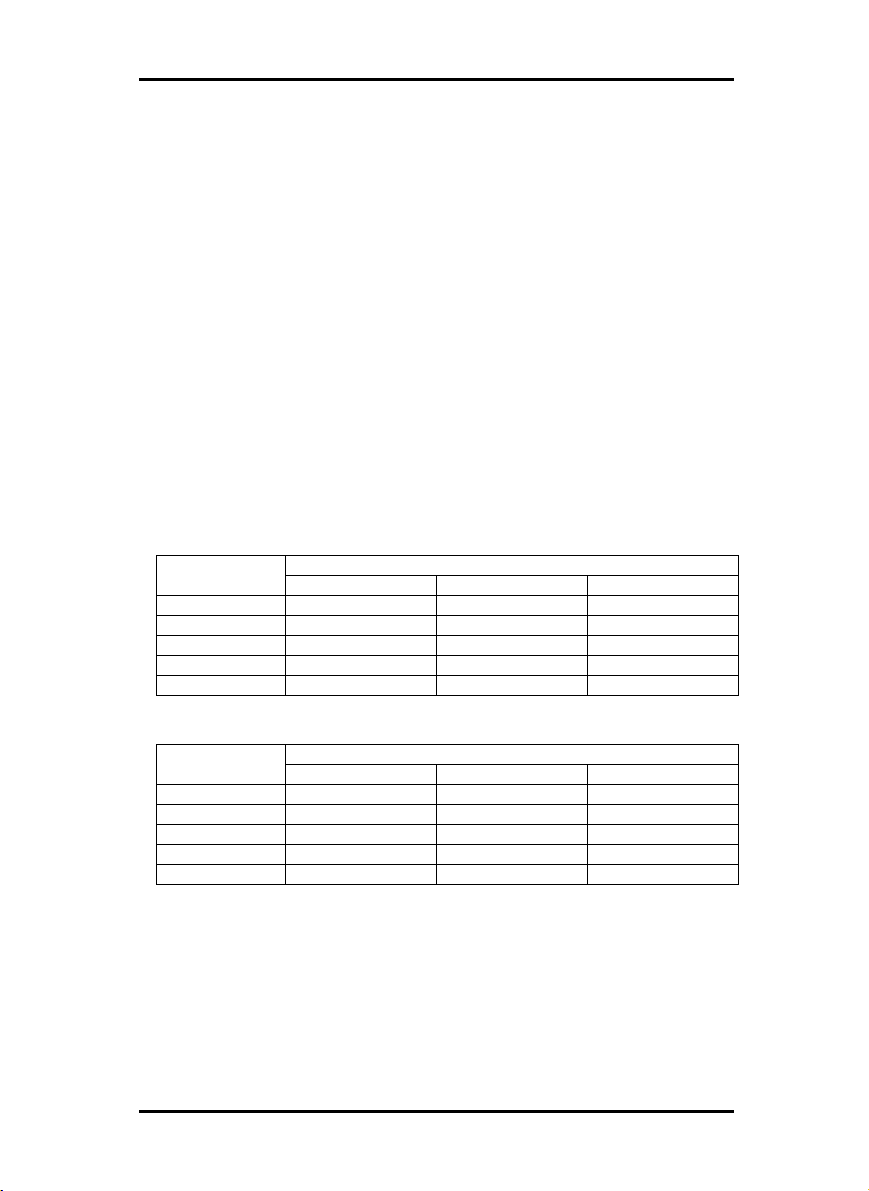
Memory requirements
In the following chart the possible sizes of plots were calculated.
The sizes of plots depend on the size of the main memory. In
the first chart you can see the results for documents with an average complexity and in the second the results for documents
with high complexity.
Further assumption are:
• All calculations are based on a transportation speed of 90
mm/s.
• Scan and plot degree is 1 bit/pixel
• Usage of average document complexity.
• Usage of 128 MB for operating system Windows 2000 and
related drivers.
MB
(1 GB) 1024 6.0 (51.443) 6.0 (51.443) 6.0 (25.721)
(1.5 GB)1536 6.0 (80.904) 6.0 (80.904) 6.0 (40.452)
MB
(1 GB) 1024 6.0 (14.698) 6.0 (14.698) 6.0 (7.349)
(1.5 GB)1536 6.0 (23.116) 6.0 (23.116) 6.0 (11.558)
Estimated with compression (average) PC memory in
Scan only Plot only simultaneous
256 6.0 (7.250) 6.0 (7.250) 3.625
512 6.0 (21.981) 6.0 (21.981) 6.0 (10.991)
768 6.0 (36.712) 6.0 (36.712) 6.0 (18.356)
Guaranteed (worst case) PC memory in
Scan only Plot only simultaneous
256 2.072 2.072 1.036
512 6.0 (6.280) 6.0 (6.280) 3.140
768 6.0 (10.489) 6.0 (10.489) 5.245
6 RW-470
Page 7

PRINTER CONTROLLER RW-470
Printer Controller RW-470
The RW-470 Software works only, if you have installed an controller. You have to install the Printer Controller RW-470 and the
appropriate software. In the next chart the technical data are
listed. In the following chapter the installation of the kernel
driver is explained.
Technical Data
Item Specification
PCI style PCI Version 2.0, Busmaster
Bus-Width 32 Bit
max. PCI bus clock 33 MHz
physical dimension 190 mm x 128 mm
PCB dimension 174,63 mm x 106,8 mm
power supply 3.3 Volts
max power consumption type. 7.5 W, max. 15 W
max memory on board 96 MB
Connection to copier Ricoh IF-cable
max. cable length 5 m
fault tolerance by software shutdown
onboard processor logic cell Spartan LCA
copier interface according Ricoh APIP
PC resources 1 x IRQ, I/O range, 2 x
memory window 32 MB
scanning binary data
plotting binary data
max pix per line 21600 pixels
scan and plot resolution 600 dpi
max scan length 6000 mm
max plot length 6000 mm
plotting speed 90 mm/sec
OS Win 2000 Professional
rasterization process 3 step pipeline mode yield
full engine speed
EMI fcc 47 part 15
RW-470 7
Page 8

PRINTER CONTROLLER RW-470
Changes to the Controller RW-470 are possible and the manufacturer does provide separate information of them.
The technical specifications comply with
Installing the Controller into your PC
Note: The Printer Controller RW-470 is – like all other
high integrated circuits – sensitive to electrostatic
charge. Therefore, remove the controller carefully from
the shipping container and do only touch it at the side
or at the bracket. Do never touch any of the circuits on
the controller with your finger. If you need to do so,
touch a metal object before you touch the controller.
1. Switch off your PC before you install the controller.
2. Select a free PCI slot according specification above. Note
that on certain computers the PCI slot #5 is not fully compatible to PCI specification 2.0. In that case do not use slot
#5 and #6.
3. Insert the controller into the PCI slot and fasten the fixing
screw. Make sure the controller is sitting well, no components touch surrounding cards or the case and that the fixing screw is set properly.
4. Re-mount the PC case. Connect the cable(s) to the plotter.
Troubleshooting
The kernel driver will only run, if an controller board was found
and all self checks were passed successfully. To see, whether the
kernel driver is running: Run ControlPanel->Devices and check
whether the device „PRINTER CONTROLLER RW-470Drv“ is running.
8 RW-470
Page 9

PRINTER CONTROLLER RW-470
If the kernel driver (device driver) „Printer Controller RW470Drv“ is not running: Start event-viewer START->Programs>Administration->Eventviewer and find out reason for failure.
Only if the PRINTER CONTROLLER RW-470DRV Driver is running, you can use the controller.
RW-470 9
Page 10

FREQUENTLY ASKED QUESTIONS
Frequently asked questions
This chapter contains an overview of which commonly asked
questions can arise when working with RW-470 PLOTBASE and
how you can solve them. See also the explanations about “error
messages” in the RW-470 PLOTBASE manual.
The topics are arranged in groups under terms, which are
sorted alphabetically:
• Jobs are not printed, indication „Please wait“ in the
status window
On the display of the plotter the interrupt button was activated. The plotter is in the offline mode and can’t receive
jobs from RW-470 PLOTBASE. If you want to recreate the
online mode, press the interrupt button.
• A file has not been included in the job list
1. Check the status bar, to see whether the interpreter is
switched on. If this is not the case, you can activate it in
the “Configuration“ menu.
2. Check whether the correct spool path is set in RW-470
CLIENTS.
• A file has not been plotted, the job status in the job
list displays a “Problem” (Color red)
The reasons could be due to the following errors:
1. General errors:
a. Check the messages in the RW-470 PLOTBASE
status window. The plotter must display the status
“Pending“.
b. Ensure that the play button is activated:
c. If you want to work in automatic print mode, ensure
that the “Auto Plot“ mode is activated.
10 RW-470
Page 11

FREQUENTLY ASKED QUESTIONS
d. Carry out a “Test plot“, to check correct function of
the plotter. For that select “Job – Test Print”.
e. Check whether the “Interrupt“ switch at the scanner
display has been activated. Deactivate it.
f. Check the connection cable between the scanner
and server.
2. File error
a. If a file certain file type (PDF, CGM, or similar.) can-
not be printed, you must first acquire the relevant licenses for these optional file formats and install a
license file.
b. The file is possibly damaged. Send the file to RW-
470 PLOTBASE again or transfer the file to the
server in another file format.
c. A printed stamp is defined larger than the drawing
format.
3. Others
a. Check whether the required type of media is avail-
able.
b. Check the width of the available plotter rolls.
• A file has not been plotted, the job in the job list has
the status “manual“ (Color light blue)
The following reasons are possible:
1. The job is password protected.
The printout can only be started manually by the user after a password has been entered.
2. Test print is activated
The printout has to be started manually, so that a test
print out can be plotted first.
• Color drawings
Colors are represented in RW-470 PLOTBASE by a raster
density. You can set the “colors” in two different ways. Open
the “Additional” tab in the job editor and click on the „Pen
Settings“ button, if the entry is a HPGL/2 or Calcomp format.
Here you can set each individual color for the respective for-
RW-470 11
Page 12

FREQUENTLY ASKED QUESTIONS
format. Either you enter the gray scale for each individual
color in percent or you set pens the pens to “Gray“ and enter
the required percentage value.
• Lines are not visible
If the file to be plotted is in a HPGL or Calcomp format, the
color can be set too light or the pen widths are too small.
• Printout plotted on an unexpected medium
The plotter can sometimes print on another roll that you expected, although you entered the default values correctly.
This can be caused by the following:
1. RW-470 PLOTBASE has a plot logic, which is instructed
to „waste“ as little paper as possible when selecting the
roll, to print as quickly as possible (preferred print direction in landscape format).
2. As the roll sizes in RW-470 PLOTBASE must be fixed
without variances, it is necessary to print on a larger roll
even if a drawing is only 0.1 mm larger than the roll selected by you. This can e.g. be the case if unfavorable
pen widths or scaling have been selected. There are
three possible ways to solve the problem:
a) Scale the drawing to e.g. 99 %,
b) Increase the setting for the number of “step
sizes/cm“: e.g. from 400 to 401. The drawing would
be reduced to 99.75 %.
c) Use a thinner pen width for the drawing frame.
• Quality loss
Especially in photos and drawings with lots of gray scales,
scaling can lead to a loss of quality. This is because the CIS
element [Contact Image Sensor] in the scanner only divides
all gray scale values into black and white due to the blackwhite threshold value and gray scale values can therefore
not be scales with the drawing.
• Scaling
The following points must always be borne in mind when
scaling drawings:
1. Photos and drawings can result in a loss of quality. C.f.
Quality loss.
12 RW-470
Page 13

FREQUENTLY ASKED QUESTIONS
2. Note the minimum pen widths when scaling. C.f. Pen
widths.
• Pen widths
Ensure that you observe the minimum pen widths for vector
images. Scaling a drawing smaller and scaling the pen
widths too can lead to loss quality and information in the
printout.
RW-470 13
Page 14

OVERVIEW OF THE FILE FORMATS
Overview of the file formats
In the following chart all file formats are listed. The standard
formats are listed in the first chart and the optional formats are
listed in the second chart. In the column „Read“ you can see,
which file format can be opened and read. In column „Write“
you can get the information which file formats can be created
after scanning or editing and which not.
Format Related
documentation
TIFF „Tagged im-
age file format
– TIFF, Revision 6.0“,
Adobe Developers Association
BMP Win-
dows/OS/2
Bitmap format
PCX „PCX format,
version 2.x-
5.x“, ZSoft
Paintbrush
T6X „The T6X file
format“, Ratio
Entwicklungen
GmbH
RLC no formal ref-
erence – different market
standards
color
depth
b/w
b/w uncom-
b/w
b/w FAX
b/w RLE
compression
uncompressed
CCITT/
3 1D
FAX
CCITT
G3
FAX
CCITT
G4
PackBits
pressed
uncompressed
RLE
runlength
coded
CCITT
G4
runlength
coded
Read Write remark
yes yes
yes yes size limits apply
yes yes size limits apply
yes yes
yes yes 16 bit size limits
14 RW-470
Page 15

OVERVIEW OF THE FILE FORMATS
CALS
HPGL,
HPGL/2
HP-RTL „HP-RTL,
Calcomp „Calcomp
WMF Windows
DODISS, Department of
Defense Index
of Specifications and
Standards
MIL-STD1840B
MIL-STD28002A
/ Version
3.2.0“, Intergraph Corporation
„The HPGL
and HPGL/2
command
set“, Hewlett
Packard
Raster Transfer
Language“,
Hewlett Packard
906/907
controller“,
Calcomp
Metafile, Microsoft
b/w FAX
b/w FAX
b/w FAX
b/w FAX
256
pens
Palette
Color
8 bit
b/w 1
bit
grey 4
bit
Palette
color
8
RGB
24
16
pens
b/w
Yes no
CCITT
G4
CCITT
G4
CCITT
Group
4
CCITT
TiledGroup
4
as
specified in
reference
HP-RTL yes yes
HP-RTL yes no
HP-RTL yes no
HP-RTL yes no
Calcomp
yes yes
yes yes
yes yes CIT „SDN 84-007
yes yes
yes no
yes no
RW-470 15
Page 16

OVERVIEW OF THE FILE FORMATS
The following file formats are optional. You can use the DWG
format only, if you have installed an AutoCAD program on your
PC.
DWG Autodesc tbd yes no
RW470PS
“RW-470PS
Level III Compatible Option”
b/w PS, EPS
Palette
color
4
Gray 4 PS, EPS
Gray 8 PS, EPS
PS, EPS
yes no
CGM „NIST CGM
ATA, Release
2.0“, National
Institute of
Standards and
Technology,
Gaithersburg,
MD 20899
Palette
color
8
RBG
24
b/w CGM
Palette
color
8
RGB
24
PS, EPS
PS, EPS
CGM
CGM
Yes No Reference:
„Interpreter
Test Specification, Reference
Pictures“, National Institute
of Standards
and Technology
16 RW-470
Page 17

ADDITIONAL FONT PATHS
Additional font paths
To enter additional font paths and thus additional fonts proceed
(if you are the administrator) as follows:
1. Open the registry editor. Select the following file:
\\HKEY_LOCAL_MACHINE\SOFTWARE\RW470\PLOTBASE\PLOTSERVER\3.0\FORMATS\RW-470PS /
EPS\
FontPath
Open an edit dialog by double clicking on the file name.
2. The existing entry “.;.\Font“ of the above figure is based on
the following syntax rules:
• . (Full stop): the font path is in the current folder
• ; (Semicolon): begins a new font path
• .\ (Full stop, back slash): the font path is in the subfolder
.\<subfolder>
The existing entry “.;.\Fonts“ means that the actual font is located in the current folder (RW-470PS / Eps) or in the
“Fonts” subfolder of the current folder.
Now enter a new font path in the “Value“ field behind the existing font path. Define additional fonts using the syntax described
above.
RW-470 17
Page 18

PRODUCING SSL FILES
Producing SSL files
The structure and commands of the SSL files are described in
this chapter. You can use the SSL commands to configure the
print job yourself. There are three classes of SSL commands:
Structured commands, SSL commands and parameters.
This description explains the structured commands first, there
then follows an alphabetical list of the SSL commands with the
corresponding parameters.
Structured commands
A job begins with BeginJob <name> and ends with EndJob.
The defaults for the plot files are defined immediately below BeginJob, and are based on commands related to the set and plot
file. The block with commands for the plot file starts with BeginOutput and ends with EndOutput.
Structured Syntax: Example:
command:
BeginJob BeginJob <name> BeginJob Project 6
EndJob EndJob BeginOutput BeginOutput EndOutput EndOutput -
Example 1:
BeginJob Project 6
Comment: EntryA
BeginOutput
OutputSize A4
Name “file2.plt“
Directory “C:\spool\ssl\Project 6“
EndOutput
Comment: EntryB
BeginOutput
OutputSize A2
Copies 2
Name “file3.plt“
Directory “C:\spool\ssl\Floorplan 3“
18 RW-470
Page 19

PRODUCING SSL FILES
EndOutput
EndJob
Example 2:
BeginJob Floorplan
Copyright "1998 Schmidt"
CreationAppl "BSP R1.01"
Comment Job Settings
JobName "TEST_1"
UserName "ROS"
Account "MAGIC“
Notes "TEST EXAMPLE"
Distribution "TO: KSC, JGE "
Copies 2
JobCollate on
JobFlagSheet Job
...
; Input Defaults
OrigDirectory "C:\\TEST"
HpglPens off
FileEmulation auto
....
; Output Defaults
Stamp text "COMPANY STAMP"
+ position bottomleft coordinate 100 100
Zoom 100. 100.
Rotate 270
...
BeginOutput
Stamp off
Zoom 100. 100.
Rotate auto
MediaType paper
Name "PLOT.000"
EndOutput
RW-470 19
Page 20

PRODUCING SSL FILES
BeginOutput
...
Stamp off
Name "PLOT.001"
...
EndOutput
EndJob
SSL commands
For each SSL command you will find descriptions, which are labeled with the abbreviations SC, C, SY, D. They mean the following:
• SC (Scope): This describes where the command can be
placed. JOB is in the area between BeginJob and the first
BeginOutput. Here there are commands, which always affect a set as a whole, e.g. Customer or e-mail, and the defaults for the SSL commands, which concern the entries. For
some SSL commands there are no meaningful defaults, e.g.
Name, these are only in the ENTRY area. The ENTRY area is
located between a BeginOutput and the corresponding
EndOutput. This is where the commands are, which exactly
concern a plot file, namely those, which are clearly labeled
with Name and Directory. A command in this area has the
highest priority, it overlays other instructions from the defaults area (JOB). If a command is not listed here, the corresponding entry from the JOB applies.
• C (comment): This contains a description of the meaning of
the command as well as the range limitations, which do not
result from the syntax.
• SY (Syntax): This is where the command syntax is written in
the form of an EBNF (Extended Backus-Naur Form).
Notes on EBNF:
- A production is represented by =.
- An exclusive Or by |
- Nonterminal symbols are labeled with pointed brackets:
<String>
20 RW-470
Page 21

PRODUCING SSL FILES
- Any number of symbols (including none) by round
brackets with asterisk: ( <Digit> )*
- More than one symbol with round brackets with Plus : (
<Digit> )+
- One or no symbols with round brackets with question
mark: ( <Whitespace> )?
A normal arithmetic bracket is also round: ( a | b )
• D (Default): This is where the program defaults are if there
is no SSL ( and no default.ssl ).
The SSL commands are listed in the following. There are three
different types of SSL commands, which are labeled in different
ways:
■ Currently supported commands
☺ commands, that you can edit
No mark: Commands, which are not supported in this product.
Account ■ ☺
SC = JOB
C = Any text, which is output in the account. Any alphanumeric string is valid.
SY = Account <string>
D = –
AddStrip
SC = JOB, ENTRY
C = replaced by → Margin top or → Margin bottom
SY = AddStrip <addstrip>
<addstrip> = leading <real> ( <unit> ) ? trailing <real> (
<unit> )?
D = –
ArchiveReference ■
SC = JOB, ENTRY
RW-470 21
Page 22

PRODUCING SSL FILES
C = any text, which is stored in the archive, to label the draw-
ing. Any alphanumeric string is valid.
SY = ArchiveReference <string>
D = –
CalComp ■ ☺
SC = JOB, ENTRY
C = settings for Calcomp files
SY = CalComp ( <calcomp> )+
<calcomp> = ( filepensize ( on | off ) ) | ( penscale ( on | off )
) | ( minwidth <real> ) | ( maxwidth <real> )
| ( stepsize <int> ) | ( patterntype ( random |
circle | ordereddither ) ) | ( ignorepensize
( on | off ) ) | ( autodetect ( on | off ) ) | (
checksum ( on | off ) ) | ( doublesync ( on | off
) ) | ( eom <int> ) | ( sync <int> )
D = auto, auto, 800, auto, auto ( not current)
CalcompColorEmulation ■
SC = JOB, ENTRY
C = Determines the corresponding gray scale values for the
pen colours, only for CalcompPens from the SSL.
SY = CalcompColorEmulation ( color <color> saturation
<int>)+
<color> = black | white | green | red | yellow | blue |
magenta | cyan | darkyellow |darkgreen | darkred | darkblue
| darkmagenta | darkcyan | gray
D = –
CalcompPens ■ ☺
SC = JOB, ENTRY
C = Pen settings for Calcomp files
SY = CalcompPens ( off | <custompen> )
22 RW-470
Page 23

PRODUCING SSL FILES
<custompen> = ( number ( <int> | <int> - <int> | all )
<pensettings> )+
<pensettings> = width <real> color <int> saturation <percent> ( pattern <patterntype> )?
<patterntype> = circle | random
D = off
Comment or ‘;’ ■ ☺
SC = JOB, ENTRY
C = any comment up to the end of the row is ignored and is
lost when processed by the program. See also Note.
SY = Comment <any> or ; <any>
D = –
Confirmation
SC = JOB
C = When switched on, stops the processing after the first
plot. Replaced by TrialPrint
SY = Confirmation ( off | on )
D = off
Copies ■ ☺
SC = JOB, ENTRY
C = Number of copies, in JOB only default for the ENTRIES.
SY = Copies <int>
D = 1
Copyright ■
SC = JOB
C = Text, which identifies the Copyright. Can be used in the
stamp.
SY = Copyright <string>
RW-470 23
Page 24

PRODUCING SSL FILES
D = –
CostCenter ■
SC = JOB
C = Text, which identifies the account. Interesting for an accounting module.
SY = CostCenter <string>
D = –
CreationAppl ■
SC = JOB
C = Text, which identifies the generating applications.
SY = CreationAppl <string>
D = –
Customer ■ ☺
SC = JOB
C = Text, which identifies the job’s customers.
SY = Customer <string>
D = –
CutMethod ■ ☺
SC = JOB, ENTRY
C = standard : Standard formats are cut.
synchro : The cuts match the plot.
SY = CutMethod ( standard | synchro )
D = synchro
DeleteAfterPlot ■
SC = JOB
C = The whole job is deleted after plotting and does not re-
main in the history.
24 RW-470
Page 25

PRODUCING SSL FILES
SY = DeleteAfterPlot ( on | off )
D = off
Directory ■
SC = ENTRY
C = The directory, in which the plot file is, absolute paths are
not currently possible, therefore, SSLs can not be simply
copied with your image directories.
SY = Directory <string>
D = –
Distribution ■ ☺
SC = JOB
C = Distribution, which can be printed on the JobFlagSheet.
SY = Distribution <string>
D = –
EarliestPlotTime
SC = JOB
C = Earliest time at which the set is to be printed.
SY = EarliestPlotTime ”YYYY:MM:DD:hh:mm”
D = –
E-Mail ■ ☺
SC = JOB
C = E-mail address to which a message is sent, when the
plot job has been completed.
SY = Email ( off | all <string> )
D = off
FileEmulation ■
SC = JOB, ENTRY
RW-470 25
Page 26

PRODUCING SSL FILES
C = Gives the file format of the plot file, if auto, the plot software decides which format is available.
SY = FileEmulation ( auto | CalComp | CALS | HPGL |
HPGL2 | PCX | TIFF | RLC | MTF )
D = auto
HeaderPosition ■ ☺
SC = JOB, ENTRY
C = Gives where the drawing header is located. Important
for folding, so that the header is visible on the top of the
folded package
SY = HeaderPosition ( ul | upperleft | ur | upperright | ll |
lowerleft | lr | lowerright | unknown )
D = lr
Hpgl ■
SC = JOB, ENTRY
C = filepensize on: Pen sizes from the plot file; off: Pen
widths from the ENTRY
filepencolor on: Pen colors from the plot file; off: Pen colors from the ENTRY
penscale on: Pen widths are scaled too; off: Pen widths are
preserved
clipping on: Drawing size is taken from the file; off: Drawing size is calculated from the vectors
minwidth: minimum pen width after scaling (see penscale )
maxwidth: maximum pen widths after scaling ( see penscale )
stepsize: Steps per centimeter
patterntype : Fill pattern for the gray implementation
ignorepensize on: Pen widths are ignored when calculating
the sizes; off: Pen thicknesses are taken into consideration
when calculating the sizes, can lead to changes in the plot
size when changing the pen widths.
bicolorrgb: Only for two-color plotters, represents one
color channel on the second page. 0 = red, 1 =
26 RW-470
Page 27

PRODUCING SSL FILES
green, 2 = blue
dithermode: for HPGL / RTL
SY = Hpgl ( <HpglStatement> )+
<HpglStatement> = ( filepensize ( on | off ) ) | ( filepcolor ( on
| off ) ) | ( penscale ( on | off ) ) | ( minwidth <real> ) | (
maxwidth <real> ) | ( stepsize <int> ) | ( patterntype (
random | circle | loadablepattern | ordereddither ) ) | (
ignorepensize ( on | off ) ) | ( bicolorrgb ( 0 | 1 | 2 ) ) | (
dithermode ( ordereddither | errordiffusion ) )
D = filepensize on, filepencolor on, penscale off, minwidth 0
(mm), maxwidth 10 (mm), stepsize 400, patterntype loadablepattern, ignorepensize off, bicolorrgb 0, dithermode
ordereddither
HpglColorEmulation ■
SC = JOB, ENTRY
C = Determines the gray scale values corresponding to the
pen colours, only for HpglPens from the SSL.
SY = HpglColorEmulation ( color <color> saturation <int> (
page ( 0 | 1 ) )? )+
<color> = see CalcompColorEmulation
D = –
HpglPens ■
SC = JOB, ENTRY
C = Pen settings HPGL Plots, saturation 0 -100 (whiteblack), pens 0 – 255. Are only effective, if filepensize and
filepencolor in Hpgl are set to off.
SY = HpglPens ( off | <custompen> )
<custompen> = see CalcompPens
D = off
Invert ■ ☺
SC = JOB, ENTRY
RW-470 27
Page 28

PRODUCING SSL FILES
C = inverts the plot
SY = Invert ( on | off )
D = off
JobCollate ■ ☺
SC = JOB
C = on: Sorts the plots in sets ( 123123); off: Prints the same
plots one after the other ( 112233 )
only effective if SetCopies > 1:
SY = JobCollate ( on | off )
D = on
JobFlagsheet ■ ☺
SC = JOB
C = The flagsheet is an information sheet, which can be
printed off for unsorted issue per set or for sorted issue
per set copy. As a standard, it contains the stamp and the
file names, further control commands are possible: job /
set = One sheet per set / set copy; text = Free text with
macros; header / trailer = in front of or behind the set;
tray <int> = roll from which the info sheet is to be
printed; size = paper size, if not given: A4; account =
with account text; distribution = with distribution text, prg
= a folding program, so that the flag sheet also lies on
the folded stack of images.
SY = JobFlagsheet ( off | <Infosize> )
<Infosize> = ( job | set ) ( text <string> )? ( header | trailer )
tray <int> size <papersize> ( account )? ( distribution )? ( prg <int> )?
D = off
JobName ■ ☺
SC = JOB
C = Name of the set ( = File name without extension )
28 RW-470
Page 29

PRODUCING SSL FILES
SY = JobName <string>
D = –
JobPlotter ■
SC = JOB
C = Controls the printout on a certain plotter, if several plot-
ters are connected to the plot server ( PLOTSERVER )
SY = JobPlotter ( auto | <string> )
D = auto
JobPriority ■
SC = JOB
C = Priority of the jobs in the queue
SY = JobPriority ( high | normal | low | wait | immediate )
D = normal
Margin ■ ☺
SC = JOB, ENTRY
C = Adds a white margin to the drawing.
SY = Margin ( off | all <real> <unit> | ( <margins> )+ )
<margins> = ( right <real> ( <unit> )? ) | ( left <real> (
<unit> )? ) | ( top <real> ( <unit> )? ) |
( bottom <real> ( <unit> )? )
D = off, values not given: 0.
MediaFeed ■
SC = JOB, ENTRY
C = Behavior if the desired paper format is not available:
larger = on larger format; smaller = on smaller format;
exact = printout only on the matching format; manual =
the operator must insert the paper manually
SY = MediaFeed ( larger | smaller | exact | manual )
RW-470 29
Page 30

PRODUCING SSL FILES
D = exact
MediaPosition ■
SC = JOB, ENTRY
C = Position of the plot on the paper.
SY = MediaPosition ( auto | <position> )
<position> = ul | upperleft | uc | uppercenter | ur | upper-
right | lc | leftcenter | cc | centercenter | rc |
rightcenter | bl | bottomleft | bc | bottomcenter |
br | bottomright
D = ul
MediaType ■ ☺
SC = JOB, ENTRY
C = Medium, on which the plot is printed.
SY = MediaType ( ( bond | paper ) | recycled paper | ( vellum
| transparent ) | ( film | polyester ) | dontcare )
D = dontcare
Mirror ■ ☺
SC = JOB, ENTRY
C = Mirror about the x- or y-axis
SY = Mirror ( off | x | y | xy )
D = off
Name ■ ☺
SC = ENTRY
C = Name of the plot file
SY = Name <string>
D = –
30 RW-470
Page 31

PRODUCING SSL FILES
Notes ■ ☺
SC = JOB, ENTRY
C = Comment on job / Plot, is retained during processing
SY = Notes <string>
D = –
OnError
SC = JOB
C = Reaction to errors; abort = abort set and continue with
the next set; continue = continue with the next entry; query
= display message and hold the plot until operator intercedes.
SY = OnError ( abort | continue | query )
D = continue
OperatorMode
SC = JOB
C = on: The plot software calls the operator when plotting
the job.
SY = OperatorMode ( on | off )
D = –
OrigDirectory ■
SC = ENTRY
C = Path, in which the original file is
SY = OrigDirectory <string>
D = –
OrigName ■
SC = ENTRY
C = Name of the original file
RW-470 31
Page 32

PRODUCING SSL FILES
SY = OrigName <string>
D = –
OutputBin ■ ☺
This is for the Input tray.
SC = JOB, ENTRY
C = Roll to be plotted from.
SY = OutputBin ( auto | manual | Bin <int> )
D = auto
OutputSize ■ ☺
SC = JOB, ENTRY
C = choice of the paper format.
window : customer-specific format, image is distorted.
proportional : customer-specific format, image proportions
are retained.
auto: the zoom setting determines the size of the printout.
SY = OutputSize ( auto | manual | <papersize> | <window> | <proportional> )
<papersize> = <DIN> | <ANSI> | <ARC>
<DIN> = ( DIN )? ( A | B | C )( 0 | 1 | 2 | 3 | 4 | 5 )
<ANSI> = ANSI ( A | B | C | D | E )
<ARC> = ARC ( A | B | C | D | E )
< window > = window <real> <real> ( <unit> )?
<proportional> = proportional <real> <real> ( <unit>
)?
D = auto
OutputTray ■
SC = JOB
C = For plotters with two trays ( front/ rear)
auto: If the set is to be folded, the whole set is sent to the
folder side. If no folding, the set comes out of the facedown tray default: A default can be set at the plot server,
32 RW-470
Page 33

PRODUCING SSL FILES
if e.g. only one tray is accessible.
front / rear: the specific output
SY = OutputTray ( auto | default | front | rear )
D = auto
Pens
SC = JOB, ENTRY
C = now → HpglPens
Placement
SC = JOB, ENTRY
C = Position of the plot on the paper: in x and y coordinates, or as a simple position
SY = Placement ( <real> <real> <unit> | <position> )
<position> = ul | upperleft | uc | uppercenter | ur | upper-
right | lc | leftcenter | cc | centercenter | rc |
rightcenter | bl | bottomleft | bc | bottomcenter
| br | bottomright
D = ul
Profile
SC = JOB
C = Identifier for a profile
SY = Profile <string>
D = –
RemoveStrip
SC = JOB, ENTRY
C = Cut the image now → Margin
SY = RemoveStrip <removestrip>
<removestrip> = leading <real> ( <unit> )? trailing <real> (
<unit> )?
RW-470 33
Page 34

PRODUCING SSL FILES
D = –
Rotate ■
SC = JOB, ENTRY
C = Rotate the image
SY = Rotate ( auto | 0 | 90 | 180 | 270 )
D = auto
SecurityPrint ■
This is for “Locked Print”.
SC = JOB
C = The set remains in the queue and is not plotted, until a
password is entered. After the password is entered the set is
given the priority immediate and DeleteAfterPlot.
The set cannot be edited without a password.
SY = SecurityPrint ( off | on | “<code>“ )
<code> = 32 Hex Digits == MD5SUM( <Password>)
D = off
SetCopies ■ ☺
SC = JOB
C = Number of set copies only in JOB.
SY = SetCopies <int>
D = 1
Stamp ■ ☺
SC = JOB, ENTRY
C = The plot is stamped with one or several defaults. Pa-
rameter: name : freely definable name of the stamp.
text : The text, which is stamped on. position : Where
the image is stamped. font, size, -attribute : Typeface,
size and style. bmp : an image can also be stamped on.
34 RW-470
Page 35

PRODUCING SSL FILES
Name and path of the image. bmporientation : where
is the image with relation to the stamp text. bmpdistance : Distance between stamp text – stamp image.
framesize : Thickness of the frame surrounding the
stamp. frametextdistance : Distance of the frame from
the text. mirror, rotate : Mirror and rotate ( 0 – 359°)
the stamp. color : Gray scale value. overlay : type of
cover if the stamp covers drawing contents. numbering :
Start number for numbering the plots for Copies > 1.
SY = Stamp ( off | <customstamp> )
<customstamp> = <stampid> ( <stampoption> )*
<stampid> = name <string> text <string>
<stampoption> = ( position <stpposition> ( coordinate
<real> <real> )? ) | ( font <systemfont> ) | ( fontsize
<int> ) | ( fontattribute ( normal | bold | italic | underline | strikeout ) ) | ( bmp <string> ) | ( bmporientation
<bmpposition> ) | ( bmpdistance <real> ( <real> )? )
| ( framesize <real> ) | ( frametextdistance <real> ) | (
mirror ( off | x | y | xy ) ) | ( rotate <int> ) | ( color (
black | darkgray | gray | lightgrey | level <percent> ) )
| ( overlay ( off | invert | transparent | opaque ) ) | (
numbering ( off | <int> ) )
<bmpposition> = ul | upperleft | uc | uppercenter | ur | up-
perright | lc | leftcenter | cc | centercenter | rc | rightcenter | bl | bottomleft | bc | bottomcenter | br |
bottomright
<stpposition> = ul | upperleft | uc | uppercenter | ur | upperright | lu | leftupper | lc | leftcenter |
lb | leftbottom | cc | centercenter | ru | rightupper | rc |
rightcenter | rb | rightbottom | bl | bottomleft | bc | bottomcenter | br | bottomright
D = off
TrialPrint ■
This is for “Sample Print”.
RW-470 35
Page 36

PRODUCING SSL FILES
SC = JOB
C = The first copy of the set is plotted, then an operator input
is waited for, to say whether the other copies are also to be
printed.
SY = TrialPrint ( on | off )
D = off
Units ■
SC = JOB
C = Unit of the job size information.
SY = Unit ( cm | mm | inch | ( points | pt | pixel ) )
D = mm
UserName ■ ☺
SC = JOB
C = User name to be able to assign the jobs.
SY = UserName <string>
D = –
Zoom ■ ☺
SC = JOB, ENTRY
C = Scaling factor. Determines the size of the drawing on the
selected paper ( OutputSize ). auto : adjusts the drawing
to the paper size. papersize : scales the drawing to a
certain format. Two whole numbers scale the drawing
in proportion to its original size.
SY = Zoom ( auto auto | <papersize> | <float> <float> )
36 RW-470
Page 37

PRODUCING CFG FILES
Producing CFG files
This chapter explains the CFG file structure and commands.
CFG files are usually produced normally automatically and are
sent with the corresponding drawing files to the RW-470
PLOTBASE. They contain the settings for the print off.
You can use the CFG commands explained in this chapter to
produce your own CFG file. To do this, you only need a simple
text editor. Save the file when ready as <Filename>.cfg.
The CFG file and the drawing file must have the same name.
Example files: tiger.cfg, tiger.tif. Copy this CFG file together with
the drawing file in the spool directory (e.g. C:\spool\cfg) of the
RW-470 PLOTBASE. Always send the CFG files first, then the
drawing files. Otherwise there is a risk that the drawing file is
automatically processed and plotted, before the actual print settings in the CFG file are available.
A CFG file could be constructed as follows:
COPYCOUNT = 1
ROTATE = 270
MIRROR = OFF
FOLD = OFF
BORDERACTIVE = ON
BORDERSAME = OFF
BORDERTOP = 5
BORDERBOTTOM = 5
BORDERLEFT = 20
BORDERRIGHT = 5
MEDIUM = PAPER
SCALEMODE = PERCENT
SCALEAUX1 = 10000
FILEPENS = ON
PEN001 = 0.25,BLACK
PEN002 = 0.35,BLACK
PEN003 = 0.5,BLACK
PEN004 = 0.7,BLACK
PEN005 = 0.1,BLACK
PEN006 = 0.5,GRAY,10
PEN007 = 0.5,GRAY,40
PEN008 = 0.5,GRAY,60
STEPSPERCM = 400
RW-470 37
Page 38

PRODUCING CFG FILES
A CFG file contains the following entries:
ENTRY VALUES EXAMPLE EXPLANATION
INPUTBIN AUTO
CUT ON
COPYCOUNT 1..999 1 Number of copies
ROTATE AUTO
INVERT ON
MIRROR OFF
FOLD OFF
SCALEMODE ORIGINAL
SCALEAUX1 ORIGINAL:
SCALEAUX2 WINDOW:
MEDIUM FILM
PRIORITY NORMAL
ENTRY VALUES EXAMPLE EXPLANATION
USER ... JOHN
1..n
OFF
0
90
180
270
OFF
X
Y
XY
1..xx
PERCENT
FORMAT
WINDOW
not used
PERCENT
Percent times 100
FORMAT:
DIN A0..DIN A6
WINDOW:
Width in 1/1200
inches
Height in 1/1200
inches
TRANSPARENT
PAPER
DONT CARE
[HIGH]
[LOW]
[WAIT]
AUTO Input tray
ON Cut immediately
after the plot is finished (synchronous
cut)
AUTO Rotation of the do-
cument (anticlockwise)
OFF Inverts the docu-
ment
OFF Mirror the docu-
ment about a certain axis
OFF Folding program of
the connected folder
ORIGINAL Scaling mode to be
used
- Defines additional
scaling details.
- Only used in ”Window“ scaling mode
PAPER
NORMAL
38 RW-470
Page 39

PRODUCING CFG FILES
SMITH
ORIGINALFILE ... C:\DEMO\
CALCOMP
PEN01
CALCOMP
PEN02..PEN16
STEPSPERCM 1..9999 800 Steps per cm
CCCHECK ON
CCSYNC01 <Characters> 2 Calcomp: ASCII-
CCSYNC02 <Characters> 0 as above for second
CCENDCHAR <Characters> 3 Calcomp: ASCII-
HPGL / HPGL2
PEN000
HPGL / HPGL2
PEN001
HPGL / HPGL2
PEN002..PEN255
RED BLACK
GREEN dto BLACK as above
YELLOW dto BLACK as above
BLUE dto BLACK as above
MAGENTA dto BLACK as above
CYAN dto BLACK as above
DARKRED dto BLACK as above
DARKGREEN dto BLACK as above
DARKYELLOW dto BLACK as above
DARKBLUE dto BLACK as above
DARKMAGENTA dto BLACK as above
DARKCYAN dto BLACK as above
BORDERACTIVE ON
Pen width of the pen
01 in 1/1000 mm
0..32Pixel 250 as above
OFF
0..9.99 mm,
<COLOR>
0..9.99 mm,
<COLOR>
0..9.99 mm,
<COLOR>
WHITE
GRAY
OFF
LAND.PLT
250 The resulting value
OFF Check sum in Cal-
0.36,WHITE
0.36,GRAY,
50
0.36,BLACK as above
GRAY, 50 Red pins are printed
OFF Activates border
must not exceed 32
pixels
comp file
Code of the first
sync character
sync character
Code for end
character
Pen thicknesses in
mm for HPGL pens
Tip: HPGL pen
numbers have three
digits.
off in certain colors
around the plot
ENTRY VALUES EXAMPLE EXPLANATION
BORDERSAME ON
OFF
ON All borders are the
same as BorderTop
RW-470 39
Page 40

PRODUCING CFG FILES
BORDERTOP 0..xxxx 0 Borders in mm
BORDERBOTTOM 0..xxxx 0 as above
BORDERLEFT 0..xxxx 0 as above
BORDERRIGHT 0..xxxx 0 as above
40 RW-470
Page 41

HPGL/2 COMMANDS AND PENS
HPGL/2 commands and pens
In this chapter we have listed all the HPGL/2 commands that the
program fully or partially supports:
+ = command is fully supported
~ = command is partially supported
• Configuration and status group:
DF = +
IN = +
IP = +
IR = +
IW = +
PG = +
RO = +
SC = +
• Vector Group:
AA = +
AR = +
AT = +
CI = +
PA = +
PD = +
PE = +
PR = +
PU = +
RT = +
• Polygon Group:
EA = +
EP = +
ER = +
EW = +
FP = +
PM = +
RA = +
RW-470 41
Page 42

HPGL/2 COMMANDS AND PENS
RR = +
WG = +
• Line and Fill Attributes Group:
AC = +
FT = +
LA = ~
LT = +
PW = +
RF = +
SM = +
SP = +
UL = +
WU = +
• Character Group:
AD = ~
CP = +
DI = +
DR = +
DT = +
DV = +
ES = +
LB = +
LO = +
SA = +
SD = ~
SI = +
SL = +
SR = +
SS = +
TD = +
• Technical Graphics Extensions:
BP = +
CT = +
DL = +
MC = +
PS = +
42 RW-470
Page 43

HPGL/2 COMMANDS AND PENS
• Palette Extension:
CR = +
NP = +
PC = +
SV = +
TR = +
• Dual-Context Extension:
No commands are supported
• Digitizing Extension:
No commands are supported
• Default values for HPGL pens:
All 256 HPGL pens have the pen thickness 0.35 mm as their
default value.
They have the following default values as colors:
Pen Color
0 white
1 black
2 red
3 green
4 yellow
5 blue
6 magenta
7 cyan
8-255 black
RW-470 43
Page 44

CALCOMP COMMANDS AND PENS
Calcomp commands and pens
In this chapter we have listed all the Calcomp commands and
their implementation status in RW-470 PLOTBASE. The standard
pen widths for the 16 Calcomp pens are given at the end of the
chapter.
+ = command is fully supported
− = command is not supported
• 951 Commands:
paper cutter −
top of form −
async −
start of plot −
force plot −
plot copies +
plotter select −
negate −
pattern fill −
hatch −
setpat −
setpen +
• Electrostatic Extensions:
newpen −
color sequence −
extended pattern fill −
area fill black/white
color modify −
extended setpen −
xsetpen black/white
extended setpat −
diskIO −
setlevel −
newlevel −
raster fill −
pixel −
plot status −
44 RW-470
Page 45

CALCOMP COMMANDS AND PENS
• Symbols Commands:
font selection + [not all symbols]
symbol string count +
plotter symbol scaling +
controller symbol scaling +
symbol characteristics +
extended characters +
select symbol set 0-4 +
plotting symbol from selected symbol set +
user defined symbol +
erase user symbol set +
• Circles Commands:
chordal tolerance +
circle command for circles +
circle command for arcs +
• Dashlines Commands:
dash bypass +
dashline +
• Additional Commands:
no operation +
pass through 8 bits direct to plotter
no operation +
newplot −
manual −
pause −
operator message −
operator message with pause −
• Calcomp pen default values:
Calcomp pens, currently 16 of them, have the following default
values for the pen width:
Pen Pen width in mm Pen width in pixels
1 0.06 1
2 0.13 2
3 0.19 3
RW-470 45
Page 46

CALCOMP COMMANDS AND PENS
Pen Pen width in mm Pen width in pixels
4 0.25 4
5 0.32 5
6 0.38 6
7 0.44 7
8 0.51 8
9 0.57 9
10 0.64 10
11 0.70 11
12 0.76 12
13 0.83 13
14 0.89 14
15 0.95 15
16 1.02 16
46 RW-470
Page 47

REGISTRY ENTRIES
Registry entries
In the registry editor you can alter several sub-trees for RW-470
PLOTBASE.
The following lists a selection of entries from the registry editor,
which can be entered during the installation of RW-470
PLOTBASE and can then be changed by you. However, not all
the entries have been listed, as either some of them should not
be changed by you or they occur several times with respect to
their meaning.
Key name: SOFTWARE\RW-470\PLOTBASE\PLOTSERVER\3.0
Name: AccountDelimiter
Type:REG_DWORD
Data:“;“
[Comment: Separator in the accounting SDF file]
Name: AccountOn
Type:REG_DWORD
Data: 00000001
[Comment: Accounting on/ off]
Name: AccountSdfFile
Type:STRING
Data: C:\RW-470\PLOTBASE\PROGRAM\Account.sdf
[Comment: Path+Name Accounting SDF File]
Name: AccountTxtFile
Type:STRING
Data: C:\RW-470\PLOTBASE\PROGRAM\Account.txt
[Comment: Path+Name Accounting TXT File]
Name: AutoPlot
Type:REG_DWORD
Data: 00000000
[Comment: AutoPlot Mode on/ off]
Name: AutoRollChange
RW-470 47
Page 48

REGISTRY ENTRIES
Type:REG_SZ
Data: 00000000
[Comment: 0: At the end of the roll only use identical roll, otherwise wait,1: At end of roll only use compatible roll, otherwise
wait}]
Name: SpoolTimeout
Type:REG_DWORD
Data: 00000000
[Comment: Timeout for incomplete jobs in seconds]
Name: Dao
Type:STRING
Data: C:\RW-470\PLOTBASE\PROGRAM\CBDB.mdb
[Comment: Path + Name of the database used by the PlotServer]
Name: Dynaset
Type:STRING
Data: SELECT ALL * FROM [T_PLOTBASE_job]
[Comment: An enquiry of the database (must not be altered)]
Name: DataPath
Type:STRING
Data: C:\RW-470\PLOTBASE\PROGRAM\Data
[Comment: Directory, in which the image files of the CFG jobs
are stored]
Name: Path
Type:STRING
Data: C:\RW-470\PLOTBASE\PROGRAM
[Comment: Program directory]
Name: SslPath
Type:STRING
Data: C:\RW-470\PLOTBASE\SSL
[Comment: Directory, in which the SSL files of all jobs are
stored]
Name: EnableQuotas
Type:REG_DWORD
48 RW-470
Page 49

REGISTRY ENTRIES
Data: 00000000
[Comment: Percentage, how much HDD capacity can be used
by the plot server]
Name: ErrorHandling
Type:REG_DWORD
Data: 00000000
[Comment: Strategy for errors that occur: 0: In case of error do
not plot any further jobs,1: In case of error plot next jobs]
Name: JobHistoryDeleteCapacity
Type:REG_DWORD
Data: 00000001
[Comment: Percentage HDD capacity, if the given limiting value
is exceed, jobs that have already been plotted are deleted until
the value is less than the limiting value]
Name: JobHistoryDeleteDate
Type:REG_DWORD
Data: 3b00e979
[Comment: Delete jobs, which are older than the given date, internal system format for date output]
Name: JobHistoryDeleteJobCount
Type:REG_DWORD
Data: 0000000a
[Comment: Number of jobs, which can be listed in the history]
Name: JobHistoryOrganization
Type:REG_DWORD
Data: 00000000
[Comment: 0: JobHistoryDeleteJobCount is used, 1: JobHistoryDeleteCapacity is used, 2: JobHistoryDeleteDate is used]
Name: JobNumber
Type:REG_DWORD
Data: 00000712
[Comment: Next job number to be assigned, do not change because otherwise database errors can occur]
RW-470 49
Page 50

REGISTRY ENTRIES
Name: LogFileName
Type:STRING
Data: %temp\\COPYBASELoggingPlot
[Comment: Path + Name of the log file, if switched on (for error detection)]
Name: Logging
Type:REG_DWORD
Data: 00000000
[Comment: logging on/ off]
Name: Server
Type:STRING
Data: RW-470 PLOTBASE - Server
[Comment: Name of the plot server]
Name: ServerExe
Type:STRING
Data: C:\RW-470\PLOTBASE\PROGRAM\PbDbRu.exe
[Comment: Path + name of the server program]
Name: SpoolDirectory
Type:STRING
Data: F:\\spool
[Comment: Spool directory]
Name: SpoolQuotas
Type:REG_DWORD
Data: 00000000
[Comment: % HDD capacity, limiting value, which new jobs can
use if the SpoolDir local]
Name: Units
Type:REG_DWORD
Data: 00000001
[Comment: 0: all details in pixels,1: all details in mm, 2: all details in inches]
Name: UseFilePrint
50 RW-470
Page 51

REGISTRY ENTRIES
Type:REG_DWORD
Data: 00000000
[Comment: FilePrint on/ off- if on, then plot to file]
Name: View
Type:STRING
Data: PLOTBASE - UI
[Comment: Name of the plot server controller]
Name: ViewOn
Type:REG_DWORD
Data: 00000001
[Comment: Fileview on/ off]
Name: DBOn
Type:REG_DWORD
Data: 00000001
[Comment: internal value for the start of the controller and the
server]
Name: SslOn
Type:REG_DWORD
Data: 00000000
[Comment: Reader on/ off]
Name: SignalLightsOn
Type:REG_DWORD
Data: 00000000
[Comment: Signal lights on / off]
Name: ResponseOn
Type:REG_DWORD
Data: 00000000
[Comment: Response System on/ off]
Name: ResponseEMail
Type:REG_DWORD
Data: 00000000
[Comment: Response E-Mail on / off]
RW-470 51
Page 52

REGISTRY ENTRIES
Name: ResponsePath
Type:STRING
Data: C:\SPOOL\response
[Comment: Path for Response file (uses RW-470 PLOTCLIENT
WEB)]
Name: FilePrintDestination
Type:STRING
Data: f:\\fileprint
[Comment: if UseFilePrint = 1, directory, where the FilePrint is
to be written to]
Name: Logging
Type:REG_DWORD
Data: 00000000
[Comment: 1: If logging switched on, 0: Logging switched off]
Name: LogLevel
Type:REG_DWORD
Data: 00000000
[Comment: If logging switched on: 1: error message, 2: Warnings, 3: Traces, 4: Reg/INI entries]
Key name: SOFTWARE\RW-470\PLOTBASE \PLOTSERVER\
3.0\PlotEngine
Name: MaxWastepaper [0=Infinite -> XXX %]
Type:REG_DWORD
Data: 00000000
[Comment: max % paper area that can be wasted]
Name: PreferedPaperOrientation[PreferNone=0, PreferPortrait=1, PreferLandscape=2]
Type:REG_DWORD
Data: 00000000
[Comment: How the printout should be printed if possible]
Name: ClockWiseAutoRotate[FALSE=0,TRUE=1]
52 RW-470
Page 53

REGISTRY ENTRIES
Type:REG_DWORD
Data: 00000000
[Comment: Direction of the drawing rotation, clockwise or anticlockwise]
Name: SizeTolerance [mm]
Type:REG_DWORD
Data: 00000002
[Comment: If the printout is this value larger than the roll available, then nevertheless plotted]
Key name:SOFTWARE\ RW-470\PLOTBASE \ PLOTSERVER\
3.0\PBWnd
These values give the colors of the jobs in the job list. The RGB
colors are given in hexadecimal figures. The last six figures are
used for this. Moving from right to left, the first two numbers
stand for “R“, the next two “G“, then “B“. Example: The color
blue is printed off with the following hexadecimal number:
00ff0000
Name: ColorPending
Type:REG_DWORD
Data: 00000000
[Comment: Color for “Idle“ status]
Name: ColorError
Type:REG_DWORD
Data: 000000c0
[Comment: Color for “Problem“ status]
Name: ColorPlotting
Type:REG_DWORD
Data: 0000c000
[Comment: Color for “Printing“ status]
Name: ColorOk
Type:REG_DWORD
Data: 00000000
[Comment: Color for “OK“ status]
RW-470 53
Page 54

REGISTRY ENTRIES
Name: ColorSecurityPlot
Type:REG_DWORD
Data: 00ff8000
[Comment: Color for “Password“ status]
Name: ColorTrialPrint
Type:REG_DWORD
Data: 00ff8000
[Comment: Color for “Test Print“ status]
Key name: SOFTWARE\RW-470\PLOTBASE\PLOTSERVER\3.0\
PBReader\Config\Registration
Name: ConfigCount
Type:REG_DWORD
Data: 00000002
[Comment: Number of spool paths]
Key name:SOFTWARE\RW-470\PLOTBASE\PLOTSERVER\3.0\
PBReader\Config\Registration\0
[Comment: settings for the first spool path]
Name: TypeName
Type: REG_SZ
Data: CFG - Interpreter
[Comment: Reference to the reader types]
Name: ConfigWindowName
Type: REG_SZ
Data: CFG
[Comment: Name of the input queue]
Name: ConfigParserPath
Type: REG_SZ
Data: F:\\SPOOL\\CFG
[Comment: Spool path]
54 RW-470
Page 55

REGISTRY ENTRIES
Name: ConfigParserTime
Type:REG_DWORD
Data: 00001388h
[Comment: Timeout for the parser]
Name: ConfigReadyFile
Type:REG_DWORD
Data: 00000000
[Comment: Activate Ready File Action; 0: False, 1:True]
Name: ConfigParserOn
Type:REG_DWORD
Data: 00000001
[Comment: Activate reader; 0: False, 1:True]
Name: ConfigDefSSLFile
Type: REG_SZ
Data: default.ssl
[Comment: Name of the default SSL file]
Name: ConfigDefCFGFile
Type: REG_SZ
Data: default.cfg
[Comment: Name of the default CFG file]
Name: AccessValue
Type:REG_DWORD
Data: 01ffffffh
[Comment: Release of print parameters]
Key name:SOFTWARE\RW-470\PLOTBASE\PLOTSERVER\3.0\
PBReader\Config\Registration\1
[Comment: settings for a further spool path]
Name: TypeName
Type: REG_SZ
Data: SSL - Interpreter
RW-470 55
Page 56

REGISTRY ENTRIES
[Comment: Reference to the reader types]
Name: ConfigWindowName
Type:REG_DWORD
Data: SSL
[Comment: Name of the input queue]
Name: ConfigParserPath
Type: REG_SZ
Data: F:\\SPOOL\\SSL
[Comment: Spool path]
Name: ConfigParserTime
Type:REG_DWORD
Data: 00001388h
[Comment: Timeout for the parser]
Name: ConfigReadyFile
Type:REG_DWORD
Data: 00000000
[Comment: Activate Ready File Action; 0: False, 1:True]
Name: ConfigParserOn
Type:REG_DWORD
Data: 00000001
[Comment: Activate reader; 0: False, 1:True]
Name: ConfigDefSSLFile
Type: REG_SZ
Data: default.ssl
[Comment: Name of the default SSL file]
Name: ConfigDefCFGFile
Type: REG_SZ
Data: default.cfg
[Comment: Name of the default CFG file, is not used]
Name: AccessValue
Type:REG_DWORD
Data: 01ffffffh
[Comment: Release of print parameters]
56 RW-470
Page 57

REGISTRY ENTRIES
Key name: SOFTWARE\RW-470\PLOTBASE\ PLOTSERVER\3.0\
PBReader\Type\Registration
Name: ReaderCount
Type:REG_DWORD
Data: 00000002
[Comment: Number of reader types]
Key name: SOFTWARE\RW-470\PLOTBASE\ PLOTSERVER\3.0\
PBReader\Type\Registration\0
[Comment: settings for a reader type]
Name: TypeExePath
Type: REG_SZ
Data: C:\RW-470\PLOTBASE\PROGRAM\ReSslru.exe
[Comment:Path of the reader]
Name: TypeName
Type: REG_SZ
Data: SSL - Interpreter
[Comment: Name of the reader]
Name: TypeReadyFilePossible
Type:REG_DWORD
Data: 00000000
[Comment: Setting, whether the reader readyfiles are processed; 0:False, 1:True]
Name: TypeWithDefaultSsl
Type:REG_DWORD
Data: 00000001
[Comment: Setting, whether a default SSL is used; do not
change]
Key name: SOFTWARE\RW-470\PLOTBASE\ PLOTSERVER\3.0\
PBReader\Type\Registration\1
[Comment: settings for a further type of reader]
RW-470 57
Page 58

REGISTRY ENTRIES
Name: TypeExePath
Type: REG_SZ
Data: C:\RW-470\PLOTBASE\PROGRAM\ReCfgru.exe
[Comment: Reader path]
Name: TypeName
Type: REG_SZ
Data: CFG - Interpreter
[Comment: Reader name]
Name: TypeReadyFilePossible
Type:REG_DWORD
Data: 00000001
[Comment: Setting, whether the Reader ReadyFiles are processed; 0:False, 1:True]
Name: TypeWithDeaultSsl
Type:REG_DWORD
Data: 00000001
[Comment: Setting, whether a default SSL is used; do not
change]
Key name: SOFTWARE\RW-470\PLOTBASE\ SCANTOOL\3.0\
Main
[Comment: settings for the RW-470 SCANTOOL]
Name: SslWorkPath
Type: REG_SZ
Data: F:\\work
[Comment: Path for the “Work“ directory]
Name: PbPlotPath
Type: REG_SZ
Data: f:\SPOOL\ssl
[Comment:Path for the spool directory in RW-470 PLOTBASE]
Name: ScanBaseSystemPath
Type: REG_SZ
58 RW-470
Page 59

REGISTRY ENTRIES
Data: C:\RW-470\PLOTBASE
[Comment:Path for RW-470 SCANTOOL]
Name: Path
Type: REG_SZ
Data: C:\RW-470\SCANTOOL\samples\
[Comment:last path used in the file selection]
Name: LastFilterRead
Type:REG_DWORD
Data: 00000001
[Comment: saves the file extension that was last used, do not
change]
Name: ScannerDriver
Type: REG_SZ
Data: SeIfD1Ru.dll
[Comment: File name of the scanner driver]
Name: SSLDefaultFile
Type: REG_SZ
Data: Default.SSL
[Comment:Name of the default SSL]
Name: MainWindow
Type:REG_DWORD
Data: 0,1,-32000,-32000,-1,-1,48,-3,638,461
[Comment: Size and position of the main window]
Name: FixedSize
Type:REG_DWORD
Data: 00000000
[Comment:Setting, whether the window is to be opened at
maximum size; 0:False, 1:True]
Name: OnlyOneInstance
Type:REG_DWORD
Data: 00000001
[Comment: Setting, whether RW-470 SCANTOOL can be
started more than once; 0:False, 1:True]
RW-470 59
Page 60

REGISTRY ENTRIES
Name: ScanBaseTempPath
Type: REG_SZ
Data: C:\DOCUME~1\ADMINI~1\LOCALS~1\Temp\
[Comment:Path of the temporary directory for RW-470
SCANTOOL]
Name: EnableScanner
Type:REG_DWORD
Data: 00000001
[Comment: Switch the scan switch on, off; do not change]
Name: ViewBrightness
Type:REG_DWORD
Data: 000000ffh
[Comment: Save the brightness values in the file view]
Name: HpglCfgFile
Type: REG_SZ
Data: C:\RW-470\PLOTBASE\HPGL.HCF
[Comment:Path for the HPGL configuration file]
Name: CcpCfgFile
Type: REG_SZ
Data: C:\RW-470\PLOTBASE\CCP.CCF
[Comment: Path for the Calcomp configuration file]
Name: DeleteAfterSslPlot
Type:REG_DWORD
Data: 00000000
[Comment: Delete the SSL files; 0:Off, 1:On]
Name: Scan2File
Type:REG_DWORD
Data: 00000000
[Comment: Automatically save the file after scanning; 0:Off,
1:On]
Name: Scan2Set
Type:REG_DWORD
60 RW-470
Page 61

REGISTRY ENTRIES
Data: 00000000
[Comment: Add scan result to the drawing set; 0:Off, 1:On]
Name: ScanToFilePath
Type: REG_SZ
Data: F:\\
[Comment: Path for ScantoFile files]
Name: ScanToFileName
Type: REG_SZ
Data: SBAUTO
[Comment:Name for ScanToFile file]
Name: ScanToFileStartNo
Type:REG_DWORD
Data: 0000002f
[Comment: Start number for ScanToFile file]
Name: ScanToFileDigits
Type:REG_DWORD
Data: 00000004
[Comment: Digits for the consecutive numbering]
Name: ScanToFileAutoStart
Type:REG_DWORD
Data: 00000000
[Comment: Automatic activation of the scan mode; 0:Off,
1:On]
Name: ScanToSaveRotation
Type:REG_DWORD
Data: 00000000
[Comment: Save the rotation setting for ScanToFile files;
0:Rotation by 0 degrees; 1:Rotation by 90 degrees, 2:Rotation
by 180 degrees, 3:Rotation by 270 degrees]
Name: DisplayDialog
Type:REG_DWORD
Data: 00000001
RW-470 61
Page 62

REGISTRY ENTRIES
[Comment: Activation of the “Scanner settings” window; 0:Off,
1:On]
Name: StampActive
Type:REG_DWORD
Data: 00000000
[Comment: Activation of the stamp function; 0:Off, 1:On]
Name: StampIFConfigName
Type: REG_SZ
Data: C:\RW-470\PLOTBASE\SCANTOOL
[Comment:Path and basic name of the stamp configurations]
Name: StampListConfigCnt
Type:REG_DWORD
Data: 00000000
[Comment: Number of stamps used; do not change]
Name: ScannerSettings
Type:REG_DWORD
Data: 1287732,2013061208,1333112,1412768,1333120,
1412776,35,366,310,733
[Comment: Position of the “Scanner Settings” window]
Name: ActiveOptionsPage
Type:REG_DWORD
Data: 00000001
[Comment: Save the tab selection in the “Options“ dialog]
Name: LastFilterWrite
Type:REG_DWORD
Data: 00000000
[Comment: Last file type saved is automatically displayed when
next file saved]
Name: LastCompression
Type:REG_DWORD
Data: 00000003
[Comment: Compression type of the last file saved, is automatically displayed when the next file is saved]
62 RW-470
Page 63

REGISTRY ENTRIES
RW-470 63
Page 64

REGISTRY ENTRIES
Key name:SOFTWARE\RW-470\PLOTBASE\ SCANTOOL\3.0\
Set
[Comment: settings for the character set]
Name: SSLEntryViewing
Type:REG_DWORD
Data: 00000001
[Comment: Display of the entries selected in the file view; 0:Off,
1:On]
Name: Ssl-Name
Type: REG_SZ
Data: SCANBASE.SSL
[Comment: File name of the last drawing set saved]
Key name:SOFTWARE\RW-470\PLOTBASE \ SCANTOOL\3.0\
Splitter\0
[Comment: Window division]
Name: DX
Type:REG_DWORD
Data: 000001e5
[Comment: horizontal window division]
Key name:
SOFTWARE\RW-470\PLOTBASE\PLOTSERVER\3.0\FORMATS
Class name:<NO CLASS>
[Comment: File formats section]
Key name:
SOFTWARE\RW470\PLOTBASE\PLOTSERVER\3.0\FORMATS\Calcomp
Name: CALC-SETTINGS
Type: REG_SZ
Data: DATA-STRUCT
64 RW-470
Page 65

REGISTRY ENTRIES
[Comment: Only for internal management]
Name: CALCOMP_CONFIG_FILE
Type: REG_SZ
Data:
[Comment: This is the path for the Config File, where the basic
settings for Calcomp are saved]
Key name:
SOFTWARE\RW470\PLOTBASE\PLOTSERVER\3.0\FORMATS\HPGL / HPGL2
Name: HP-FONTPATH
Type: REG_SZ
Data:
[Comment: This is the path for the Ratio HPGL font files.]
Name: HPGL_CONFIG_FILE
Type: REG_SZ
Data:
[Comment: This is the path for the Config File where the basic
settings for HPGL / HPGL2 are saved]
Name: HP-PLOTTERCOLORDEFAULT
Type: REG_SZ
Data: DATA-STRUCT
[Comment: Only for internal management]
Name: HP-PLOTTERMODE
Type: REG_SZ
Data: DATA-STRUCT
[Comment: Only for internal management]
Name: HP-PLOTTERPENDEFAULT
Type: REG_SZ
Data: DATA-STRUCT
[Comment: Only for internal management]
RW-470 65
Page 66

REGISTRY ENTRIES
Name: HP-SETTINGS
Type: REG_SZ
Data: DATA-STRUCT
[Comment: Only for internal management]
Key name:
SOFTWARE\RW-470\PLOTBASE\PLOTSERVER\3.0\FORMATS\
Intergraph
Name: TileDX
Type: REG DWORD
Data: This is where the tile width is when saving this format,
there are no facilities in the application for adjusting this value.
[Comment: Default value 512]
Name: TileDY
Type: REG DWORD
Data: This is where the tile height is when saving this format,
there are no facilities in the application for adjusting this value.
[Comment: Default value 512]
Key name:
SOFTWARE\RW-470\PLOTBASE\PLOTSERVER\3.0\FORMATS\
TIFF
Name: TileDX
Type: REG DWORD
Data: This is where the tile width is when saving this format,
there are no facilities in the application for adjusting this value.
[Comment: Default value 512]
Name: TileDY
Type: REG DWORD
Data: This is where the tile height is when saving this format,
there are no facilities in the application for adjusting this value.
[Comment: Default value 512]
66 RW-470
Page 67

REGISTRY ENTRIES
Key name:
SOFTWARE\RW470\PLOTBASE\PLOTSERVER\3.0\FORMATS\Windows Metafile
Name: Default Dpi
Type: REG DWORD
Data: This is where the default Dpi is.
[Comment: Default value 400]
Name: Default Lpi
Type: REG DWORD
Data: This is where the default Lpi is.
[Comment: Default value 400]
Name: Default DX
Type: REG DWORD
Data: This is where the default image width is with which the
WMF should be loaded.
[Comment: Default value 512]
Name: Default DY
Type: REG DWORD
Data: This is where the default image height is with which the
WMF should be loaded.
[Comment: Default value 400]
Key name:
SOFTWARE\RW-470\PLOTBASE\PLOTSERVER\3.0\FORMATS\
Portable Document Format (PDF)
Name: BasePath
Type: REG_SZ
Data: Basic path to the ghostscript files.
[Comment: Should always be set to ’’.“ so that the ghostscript
files can be correctly loaded]
Name: FontPath
Type: REG_SZ
Data: Path to the ghostscript font files.
RW-470 67
Page 68

REGISTRY ENTRIES
[Comment: Default “.;.\Font“ ]
Name: IncludePath
Type: REG_SZ
Data: Additional path for font files
[Comment:]
Name: Device
Type: REG DWORD
Data: 0 No color channel
1 Red
2 Green
3 Blue
[Comment: Default 0, color channel for BiColorMode]
Name: EnableBiColor
Type: REG DWORD
Data: 0 BiColorMode switched on
1 BiColorMode switched off
[Comment: Is set internally]
Name: EnableLogging
Type: REG DWORD
Data: 0 for Logging switched off
1 for Logging switched on
[Comment: Default 0]
Name: HalfToneAccurateScreens
Type: REG DWORD
Data: 0 functionality switched off
1 functionality switched on
[Comment: Grayscale manipulation]
Name: HalfToneAngle
Type: REG DWORD
Data: 0 - 90
[Comment: Grayscale manipulation]
Name: HalfToneDefaultSelect
Type: REG DWORD
68 RW-470
Page 69

REGISTRY ENTRIES
Data: ComboBox selection (0 - 4)
Additional entries possible
[Comment: Default 0]
Name: HalfToneFrequency
Type: REG DWORD
Data: 1 - 999
[Comment: Grayscale manipulation]
Name: HalfToneManual
Type: REG DWORD
Data: 0 Manual settings off
1 Manual settings on
[Comment: Grayscale manipulation]
Name: HalfToneMode
Type: REG DWORD
Data: 0 Background manipulation
1 General manipulation
2 Grayscale manipulation
[Comment: Grayscale manipulation]
Name: HalfToneSpotFunction
Type: REG DWORD
Data: ComboBox selection (0 - 22)
[Comment: Grayscale manipulation]
Name: HalfToneTransferFunction
Type: REG DWORD
Data: ComboBox selection (0 - 7)
[Comment: Grayscale manipulation]
Name: HalfToneWidthHeight
Type: REG DWORD
Data: 1 – 7 (Filter matrix dimension)
[Comment: Grayscale manipulation]
Name: PDFHalftoningUserDef
Type: REG_SZ
Data: DATA-STRUCT
RW-470 69
Page 70

REGISTRY ENTRIES
[Comment:]
Name: PDFSettings
Type: REG_SZ
Data: DATA-STRUCT
[Comment:]
Name: UseHalftoning
Type: REG DWORD
Data: 0 Halftoning switched off
1 Halftoning switched on
[Comment: Default 0]
Name: UseScaling
Type: REG DWORD
Data: not used for PDF
[Comment: Default 1]
Key name:
SOFTWARE\RW470\PLOTBASE\PLOTSERVER\3.0\FORMATS\RW-470PS / EPS
Name: BasePath
Type: REG_SZ
Data: Basic path to the ghostscript files.
[Comment: Should always be set to ’’.“ so that the ghostscript
files can be correctly loaded]
Name: FontPath
Type: REG_SZ
Data: Path to the ghostscript font files.
[Comment: Default “.;.\Font“ ]
Name: Additional font paths
Type: REG_SZ
Data: This entry is not used
Extra Registry entry( not under PDF or RW-470PS)
[Comment:]
70 RW-470
Page 71

REGISTRY ENTRIES
Name: IncludePath
Type: REG_SZ
Data: Additional path for font files
[Comment:]
Name: Device
Type: REG DWORD
Data: 0 No color channel
1 Red
2 Green
3 Blue
[Comment: Default 0, Color channel for BiColorMode]
Name: EnableBiColor
Type: REG DWORD
Data: 0 BiColorMode switched on
1 BiColorMode switched off
[Comment: Is set internally]
Name: EnableLogging
Type: REG DWORD
Data: 0 for Logging switched off
1 for Logging switched on
[Comment: Default 0]
Name: HalfToneAccurateScreens
Type: REG DWORD
Data: 0 : functionality switched off
1 : functionality switched on
[Comment: Grayscale manipulation]
Name: HalfToneAngle
Type: REG DWORD
Data: 0 - 90
[Comment: Grayscale manipulation]
Name: HalfToneDefaultSelect
Type: REG DWORD
Data: ComboBox selection (0 - 4)
Additional entries possible
RW-470 71
Page 72

REGISTRY ENTRIES
[Comment: Default 0]
Name: HalfToneFrequency
Type: REG DWORD
Data: 1 - 999
[Comment: Grayscale manipulation]
Name: HalfToneManual
Type: REG DWORD
Data: 0 Manual settings off
1 Manual settings on
[Comment: Grayscale manipulation]
Name: HalfToneMode
Type: REG DWORD
Data: 0 Background manipulation
1 General manipulation
2 Grayscale manipulation
[Comment: Grayscale manipulation]
Name: HalfToneSpotFunction
Type: REG DWORD
Data: ComboBox selection (0 - 22)
[Comment: Grayscale manipulation]
Name: HalfToneTransferFunction
Type: REG DWORD
Data: ComboBox selection (0 - 7)
[Comment: Grayscale manipulation]
Name: HalfToneWidthHeight
Type: REG DWORD
Data: 1 – 7 (Filter matrix dimension)
[Comment: Grayscale manipulation]
Name: TPSHalftoningUserDef
Type: REG_SZ
Data: DATA-STRUCT
[Comment:]
72 RW-470
Page 73

REGISTRY ENTRIES
Name: RW-470PSSettings
Type: REG_SZ
Data: DATA-STRUCT
[Comment:]
Name: UseHalftoning
Type: REG DWORD
Data: 0 Halftoning switched off
1 Halftoning switched on
[Comment: Default 0]
Name: UseScaling
Type: REG DWORD
Data: 0 Scaling switched off
1 Scaling switched on
[Comment: Default 1, should usually be switched on. Only
switch off in exceptional situations, if the PS file is not correctly
scaled.]
RW-470 73
Page 74

INDEX
Index
C
Calcomp
Commands................. 44
Pens ........................... 45
CE-Certification ................8
CFG-File
Commands................. 38
F
File formats ....................14
Font path .......................17
Front Side Bus ..................5
H
Hard drive........................ 5
Hardware......................... 5
HPGL/2-Commands....... 41
M
Memory ...........................6
Monitor............................ 6
N
P
PCI Bus............................ 5
Printer Controller.............. 7
Problems
Colored drawings ....... 11
Data exchange ........... 10
Lines not visible........... 12
Loss of quality............. 12
No Entry..................... 10
No print out................ 10
Pen widths .................. 13
Scaling ....................... 12
Wrong format............. 12
Processor ......................... 5
R
Registry Entries ............... 47
S
SSL-File
Commands ................ 18
System memory................ 5
System requirements......... 5
Network ...........................5
74 RW-470
 Loading...