


RW-470
CLIENTS
Final Version 11/12/2001

Trademarks
Adobe
, Acrobat, PostScript and PostScript3TM are registered trademarks of
Adobe Systems Incorporated.
Apple, Macintosh, Mac and TrueType are registered trademarks of Apple Computer,
Incorporated.
AutoCAD
and DWG are registered trademarks of Autodesk, Inc.
HPGL, HPGL/2 and HP-RTL are registered trademarks of Hewlett-Packard Company.
Ethernet
Microsoft
Microsoft Corporation in the United States and/or other countries.
Netscape Navigator
poration, Mountain View/USA.
PLOTBASE
Germany.
PLOTCLIENT
is a registered trademark of Xerox Corporation.
, Outlook, Windows and Windows NT are registered trademarks of
is a registered trademark of Netscape Communications Cor-
is a registered trademark of RATIO Entwicklungen GmbH, Hamburg,
is a registered trademark of RATIO Entwicklungen GmbH, Hamburg,
Germany.
RATIO SSL is a registered trademark of RATIO Entwicklungen GmbH, Hamburg,
Germany.
Calcomp is a registered trademark of Calcomp Inc..
CALS is a registered trademark of U.S. Department of Defense, USA.
CGM is a registered trademark of Henderson Software Inc., Boulder, USA.
CIT is a registered trademark of Intergraph GmbH, Ismaning, Germany
PCX is a registered trademark of Zsoft, Microsoft Inc.
WMF is a registered trademark of Microsoft Corporation in the United States and/or
other countries.
Other product names used herein are for identification purposes only and might be
trademarks of their respective companies. We disclaim any and all rights in those
marks.
The proper names of the Windows operating systems are as follows:
Microsoft
Microsoft
Microsoft
Microsoft
Microsoft
Microsoft
Microsoft
Windows 95 operating system
Windows 98 operating system
Windows Millennium Edition
Windows 2000 Professional
Windows 2000 Server
Windows NT Server operating system Version 4.0
Windows NT Workstation operating system Version 4.0
Note:
“RW-470 PS” stands for RW-470 Postscript Level 3 Compatible Option

CONTENTS
Contents
RW-470 PLOTCLIENTS ......................................................... 7
Manual conventions..................................................................... 9
Part I – RW-470 PLOTCLIENT WIN ....................................10
Introduction ......................................................................11
Installation .......................................................................12
System requirements .................................................................. 12
Installation of the RW-470 PLOTCLIENT WIN.............................. 13
Start and quit program ....................................................15
Program window ..............................................................16
Program sequence............................................................17
Name conventions ..................................................................... 17
From the drawing to the job ....................................................... 18
Job and entry in the chart........................................................... 20
Tools .................................................................................22
Main symbol bar........................................................................ 22
Icon bar .................................................................................... 23
Presets ..............................................................................25
Setting the SSL defaults .............................................................. 25
“General“ tab............................................................................ 25
Set up SSL spool paths .......................................................... 27
“Format“ tab ............................................................................. 29
Job editor..........................................................................30
“Job” tab................................................................................... 30
Default settings area .................................................................. 32
“Default Specific“ tab ............................................................ 33
“Default Additional“ tab ........................................................ 37
“Entry“ area............................................................................... 38
Stamp editor ..................................................................... 40
Make stamp .............................................................................. 40
Stamp configurations ................................................................. 41
RW-470 CLIENTS 3

CONTENTS
Edit or delete stamp ................................................................... 41
“Settings“ tab............................................................................. 42
“Data“ tab................................................................................. 44
Pen settings ......................................................................47
View the changes....................................................................... 47
HPGL/2 - Pens........................................................................... 48
HPGL/2 - Colors........................................................................ 50
HPGL/2 - Misc........................................................................... 51
Calcomp - Pens ......................................................................... 55
Calcomp - Colors ...................................................................... 56
Calcomp - Misc ......................................................................... 57
Collate jobs ....................................................................... 61
Add entries ................................................................................ 62
Add with button .................................................................... 62
Add using the right-hand mouse button ................................. 63
Add with menu item .............................................................. 63
Add with Drag & Drop .......................................................... 64
Add multiple entries ................................................................... 64
Delete entries ............................................................................ 65
Entry information ....................................................................... 66
Part II – RW-470 WINPRINT..............................................67
Introduction ......................................................................68
Installation .......................................................................69
Configuration.................................................................... 70
Print Parameters of RW-470 WINPRINT (16 bit)........................... 70
“Details“ tab ......................................................................... 70
“General Settings“ tab .......................................................... 71
“Job Processing“ tab ............................................................. 72
Print Parameters of RW-470 WINPRINT (32 bit)........................... 72
Part III – RW-470 PLOTCLIENT HDI/ADI ...........................75
Introduction ......................................................................76
Installation .......................................................................77
4 RW-470 CLIENTS

CONTENTS
Configuration.................................................................... 83
Configuration for AutoCAD 13/14 via configuration tool ............ 83
Settings for AutoCAD 13/14 in print dialog................................. 84
Settings for AutoCAD 2000 in print dialog .................................. 85
Presets for print jobs ........................................................87
“Main menu“ tab ....................................................................... 87
“Extended“ tab........................................................................... 89
“Options“ tab ............................................................................ 90
Part IV – RW-470 PLOTCLIENT WEB ..................................92
Introduction ......................................................................93
Installation .......................................................................94
Configuration.................................................................... 95
Open the configuration page ..................................................... 95
Access rights for users................................................................ 96
Set spool path (upload) .............................................................. 98
Additional settings (misc.) ........................................................... 99
E-mail (e-mail)......................................................................... 100
Administrator password (admin) ............................................... 101
Prepare print jobs ..........................................................102
Plot sequence .......................................................................... 102
Open and log on..................................................................... 102
Settings for the job (job parameters) ......................................... 103
Print parameters for entries (entry defaults) ............................... 107
General print parameters .................................................... 107
Stamp settings .................................................................... 109
Pen settings (pen settings)......................................................... 110
HPGL ................................................................................. 111
Calcomp ............................................................................ 113
Add local entry, add multiple.................................................... 115
Local files or ZIP-Archive (add local entry)............................ 116
ZIP-Archive with SSL-job ...................................................... 116
Several local files (add multiple) .......................................... 117
Entry list................................................................................... 118
Edit and delete entries (select, delete) ....................................... 119
Send job (Submit job)............................................................... 119
RW-470 CLIENTS 5

CONTENTS
Query current job status (queue status) ..................................... 120
Plotter status (plotter status) ...................................................... 120
Incomplete jobs ....................................................................... 121
Corrective maintenance..................................................122
Part V – RW-470 PLOTCLIENT MAC ................................. 123
Installations .................................................................... 124
Installations on Server PC with Windows 2000 .......................... 124
Installation on the Macintosh computer..................................... 124
Print jobs and presets.....................................................126
MainOptions1 ......................................................................... 126
MainOptions2 ......................................................................... 127
JobOptions.............................................................................. 128
Part VI – RW-470 PLOTCLIENT LPR/FTP ..........................130
RW-470 PLOTCLIENT LPR ................................................131
Configuration on Server PC with Windows 2000 ....................... 131
Print jobs with lpr on Windows 2000 ........................................ 132
Configuration on UNIX ............................................................ 132
Print jobs on UNIX using lpr ..................................................... 133
RW-470 PLOTCLIENT FTP ................................................134
Configuration on Server PC with Windows 2000 ....................... 134
Print jobs on Windows 2000 using ftp....................................... 134
Configuration on UNIX ............................................................ 135
Print jobs on UNIX using ftp...................................................... 136
Part VII – Appendix.........................................................138
Index...............................................................................139
6 RW-470 CLIENTS

RW-470 PLOTCLIENTS
RW-470 PLOTCLIENTS
RW-470 PLOTCLIENTSRW-470 PLOTCLIENTS
RW-470 PLOTCLIENTS
This manual explains the installation and operation of RW-470
PLOTCLIENTs as well as two networks. You find out how you can
use the RW-470 PLOTCLIENTs or network protocols to produce
print jobs, set print parameters and to send the print jobs to the
RW-470 PLOTBASE server program. The following RW-470
PLOTCLIENTs and protocols are described:
• RW-470 PLOTCLIENT WIN
• RW-470 WINPRINT
• RW-470 PLOTCLIENT HDI/ADI
• RW-470 PLOTCLIENT WEB
• RW-470 PLOTCLIENT MAC
• RW-470 PLOTCLIENT LPR
• RW-470 PLOTCLIENT FTP
The following gives a brief explanation of all RW-470 PLOTCLI-
ENTs. The precise functional descriptions are given in the re-
spective chapters:
• RW-470 PLOTCLIENT WIN
RW 470 PLOTCLIENT WIN is available for Microsoft Windows
NT 4.0, Microsoft Windows 2000 and Microsoft Windows
95/98/ME and is a program for preparing plot jobs, which it
then sends to RW-470 PLOTBASE. This is done by collating set-
based jobs.
• RW-470 WINPRINT
The Windows printer driver RW-470 WINPRINT allows print jobs
from Windows applications, to then pass them directly to RW-
470 PLOTBASE as a job.
• RW-470 PLOTCLIENT HDI/ADI
With RW-470 PLOTCLIENT HDI/ADI you produce HPGL/2-files
from the drawings and documents, which have been produced
in the AutoCAD programs AutoCAD R13, AutoCAD R14, Auto-
CAD 2000, AutoCAD 2000i, AutoCAD 2000 LT or AutoCAD
2000 LTi. The print jobs can be sent to the RW-470 PLOTCLIENT
RW-470 CLIENTS 7

RW-470 PLOTCLIENTS
RW-470 PLOTCLIENTS
RW-470 PLOTCLIENTSRW-470 PLOTCLIENTS
WIN program or directly to the RW-470 PLOTBASE server pro-
gram.
• RW-470 PLOTCLIENT WEB
The RW-470 PLOTCLIENT WEB enables you to send print jobs to
RW-470 PLOTBASE both via the Intranet as well as via the Inter-
net. You can stipulate numerous print parameters. Successful
processing of the print processes in RW-470 PLOTBASE can be
controlled via a status message. Equally, you can also have an
e-mail sent to obtain a message on successful job completion.
• RW-470 PLOTCLIENT MAC
With the printer driver RW-470 PLOTCLIENT MAC, you can send
print jobs to RW-470 PLOTBASE from applications, which run on
the Macintosh operating system Mac OS 9.x.
• RW-470 PLOTCLIENT LPR
With the lpr command, you can send print jobs to RW-470
PLOTBASE via RW-470 WINPRINT, without having to use an ap-
plication program. This printing facility is particularly meant for
UNIX users.
• RW-470 PLOTCLIENT FTP
With the ftp command you can send print jobs to RW-470
PLOTBASE without having to use an application program. This
printing facility is particularly meant for UNIX users.
We wish you every success in your work with RW-470 CLIENTs.
8 RW-470 CLIENTS

RW-470 PLOTCLIENTS
RW-470 PLOTCLIENTS
RW-470 PLOTCLIENTSRW-470 PLOTCLIENTS
Manual conventions
In the text, you can come across two possible terms, which are
intended to point out special circumstances or advantages or
even to warn you against certain work steps:
Note: You are free to decide whether you wish to fol-
low the recommendation given in a note or not. Notes
are usually used to draw your attention to special circumstances or even to point out useful commands or
ones that are easily forgotten and overseen.
Attention: It is advisable to take particular notice of
any possible problems marked with “Attention“ to e.g.
avoid problems with your data stocks, etc
RW-470 CLIENTS 9

Part I – RW-470 PLOTCLIENT WIN
10 RW-470 CLIENTS

INTRODUCTION
Introduction
This part of the manual describes the program RW-470
PLOTCLIENT WIN. RW-470 PLOTCLIENT WIN is available for
Microsoft Windows NT, for Microsoft Windows 95/98/ME as well
as for Microsoft Windows 2000 and is a program for preparing
plot jobs, which it then sends to the server program, RW-470
PLOTBASE. This is carried out by collating set-based jobs.
The Client-Server architecture of RW-470 PLOTBASE enables
each connected user to define their print jobs and drawing sets
themselves and to send them to RW-470 PLOTBASE for output.
The interface used between RW-470 PLOTBASE and the Client is
the Interpreter, which covers the Clients’ information so that RW-
470 PLOTBASE can easily work through the set requirements.
Compliance of standards in conjunction with the graphic user
interface of Microsoft Windows enables problem-free integration
in existing environments and applications.
RW-470 CLIENTS 11

INSTALLATION
Installation
In this chapter you can read about which system requirements
have to be fulfilled and how to carry out the installation. Fur-
thermore, all the new [sub-] directories and file types that you
will find on your harddrive following the installation are listed in
their own section.
System requirements
Please read through the following recommendations carefully.
They can be very helpful in finding the optimum hardware for
your requirements.
• Operating system
Windows NT 4.0, Windows 95/98/ME or Windows 2000. For
Windows 2000 we recommend Service Pack 1. You can use a
higher Service Pack version, too, but if it does not run, please
change back again to Service Pack 1.
• Network interface/Configuration:
10/100 Base T Ethernet, the TCP/IP configuration is necessary
• Processor & System memory
Dependent on your operating system we recommend following
processors and system memory:
Windows 95/98: Pentium II 233 MHz, at least 32 MB RAM
Windows ME: Pentium II 233 MHz, at least 64 MB RAM
Windows NT 4.0: Pentium II 200 MHz, at least 64 MB RAM
Windows 2000: Pentium II 200 MHz, at least 64 MB RAM
• Harddrive
At least 500 MB.
• Monitor
At least 1024 x 768 pixels resolution.
12 RW-470 CLIENTS

INSTALLATION
INSTALLATION
INSTALLATIONINSTALLATION
Installation of the RW-470 PLOTCLIENT WIN
This section describes the installation of the program and which
file types and directories you should find on your harddrive fol-
lowing the installation.
To install the program, please proceed as follows:
1. Start Windows NT as a user with administrator rights and
open Windows NT Explorer.
2. If Windows NT was already started [with administrator rights],
please quit all running programs or backup the data stocks.
3. Change via network to installation folder \\<Server>\ Tools
\PLOTCLIENT_WIN.
4. Start the file SETUP.EXE.
5. Select the SETUP language, and then click on OK.
6. Click on NEXT.
7. Click on YES, if you agree to the license agreement. Click on
NO, if you do not agree and want to abort the installation.
8. Answer the question about the Readme-file, and click on
NEXT.
9. Click on NEXT, to confirm the target folder, in which RW-470
PLOTCLIENT WIN is to be installed.
10. Click on NEXT, to confirm the unchanged or changed program folder.
11. Determine the SSL Spool folder. The standard preset is the
folder “\\<Server>\Spool\SSL“.
The first part “\\<Server>“ gives the destination computer,
on which RW-470 PLOTBASE is installed. The second part
“\Spool\SSL“ gives the spool folder released there.
12. RW-470 PLOTCLIENT WIN is then installed.
13. Read the Readme-file or start RW-470 PLOTCLIENT WIN.
14. If you now start RW-470 PLOTCLIENT WIN – for the first time,
you will be asked to enter the default values for new SSL print
jobs. Answer the query with “OK“.
15. Enter the global job information on the “job“ tab in the job
editor job information.
16. Change to the “Default specific“ and “Default additional“
tabs, and enter the detailed defaults. The possible settings in
the job editor are described in detail from Page 30.
17. Quit your defaults with “OK“.
RW-470 CLIENTS 13

INSTALLATION
18. Answer the query about preparing a job example.
19. If you answer with “YES“, RW-470 PLOTCLIENT WIN prepares a job example, which you can send off straight away as
the first print job.
14 RW-470 CLIENTS

START
START AND QUIT PROGRAM
STARTSTART
Start and quit program
• Start program
The installation program sets up its own program group with
program symbols towards the end of the installation. To start
RW-470 PLOTCLIENT WIN, open it via the “Start“ bar or double
click on its program symbol.
Your first sample print is easy to manage and will already be
started at the end of your installation. For explanations you will
have to read in following two chapters „From the drawing to the
job“ on page 18 and „Job editor“ on page 30.
• Quit program
You can either quit RW-470 PLOTCLIENT WIN via the menu
item “File - Exit“ or with the usual Windows keyboard shortcut
“ALT+F4“.
The program’s functions are now described in the following
chapters.
RW-470 CLIENTS 15

PROGRAM WINDOW
Program window
16 RW-470 CLIENTS

PROGRAM
PROGRAM SEQUENCE
PROGRAMPROGRAM
Program sequence
This chapter provides you with an overview of how the drawing
gets into the job list of RW-470 PLOTBASE and is then printed. At
the end of the chapter you will find a graphic, which illustrates
the job flow.
Together with the introductory chapter, this chapter is intended to
help you to bet to know the environment and the embedding of
the program in it.
In addition, the most important terms used in the program are
also explained.
Name conventions
Job:
A job is a print job, which includes at least one entry or set of
entries, which are to be printed off on the plotter as a specific
combination and with individual settings. The job can, inter alia,
be complied using RW-470 PLOTCLIENT WIN and can include
an unlimited number of entries.
User:
The user, or job producer, prepares the jobs with RW-470
PLOTCLIENT WIN. The user can simultaneously be the client.
Client:
The client places an order, to have one or several drawings
printed out via RW-470 PLOTBASE on the plotter. The client can
simultaneously be the user. The client is also the recipient of the
printed and, optionally folded drawings.
Entry:
An entry is a drawing with the corresponding description, required for RW-470 PLOTBASE. This description contains all the
information about the drawings, e.g. target format, output medium, drawing header, etc. Entries are compiled in RW-470
PLOTCLIENT WIN to form jobs or can also represent a job singly.
RW-470 CLIENTS 17

PROGRAM SEQUENCE
The entries or drawings can have the following file formats,
which RW-470 PLOTCLIENT WIN recognizes from the file extension:
• Calcomp [*.906, *.907]
• CALS MIL-STD 1840B,28002A [*.cal]
• DWG [*.dwg]
• HPGL/2, HP-RTL [*.plt, *rtl]
• Intergraph [*.cit, *.tg4]
• PCX [*.pcx]
• RLC [*.rlc]
• T6X [*.t6x]
• TIFF G4 [*.tif]
• Windows Metafile [*wmf]
• Windows OS/2 Bitmap [*.bmp]
As an option, the file format CGM [*.cgm] as well as PDF and
postscript, i.e. RW-470 Postscript Level 3 Compatible Option are
also available [*.pdf, *.ps]. The file format DWG can only be
used if AutoCAD (2000 or 2000i) is installed on RW-470
PLOTBASE server PC.
SSL-file:
The SSL-file is automatically produced by RW-470 PLOTCLIENT
WIN when preparing a job and contains all the information
about the job itself as well as all the descriptions of the individual
entries.
The SSL file is required by RW-470 PLOTBASE, to be able to print
off a job on the plotter.
Draftsman:
The [technical] draftsman/draftswoman produces the drawings
for the client, which can later be collated by the user to form
jobs.
From the drawing to the job
The following lists the path of a drawing from its preparation
through to the job list of RW-470 PLOTBASE. The work steps are
presented functionally and not person-related, i.e. that several
functions can be carried out by the same person.
18 RW-470 CLIENTS

PROGRAM
PROGRAM SEQUENCE
PROGRAMPROGRAM
With the help of this section, the following graphic and the first
chapter of the manual, you should be able to grasp the task and
possible applications of RW-470 PLOTBASE and the environment.
1. PRODUCTION:
The [technical] draftsman/draftswoman produces the drawing
using an EDM, CAD or similar system and saves it in one of
the following formats, which are identified by RW-470
PLOTBASE from the file extension:
• Calcomp [*.906, *.907]
• CALS MIL-STD 1840B,28002A [*.cal]
• DWG [*.dwg]
• HPGL/2, HP-RTL [*.plt, *rtl]
• Intergraph [*.cit, *.tg4]
• PCX [*.pcx]
• RLC [*.rlc]
• T6X [*.t6x]
• TIFF G4 [*.tif]
• Windows Metafile [*wmf]
• Windows OS/2 Bitmap [*.bmp]
As an option, the file formats CGM [*.cgm] as well as PDF
and postscript, i.e. RW-470 Postscript Level 3 Compatible
Option are also available [*.pdf, *.ps]. The file format DWG
can only be used if AutoCAD (2000 or 2000i) is installed on
RW-470 PLOTBASE server PC.
2. DRAG & DROP:
The user brings all the drawings intended for printing into
RW-470 PLOTCLIENT WIN using Drag & Drop or using the
“insert entry” or “add entry“ functions.
3. PREPARE ORDER:
The user collates the drawings to form jobs in RW-470
PLOTCLIENT WIN, assigns print settings and checks the
drawing using check preview.
4. PROVISION:
As soon as the user has produced the jobs, they automatically
send them via the network [LAN] to the directories provided
RW-470 CLIENTS 19

PROGRAM SEQUENCE
using the program command, “File – Print SSL“, thereby
making them available for RW-470 PLOTBASE to print.
5. COLLECTION:
RW-470 PLOTBASE regularly reads the directories and thus
checks whether new jobs are ready for printing. As soon as a
job is ready, it is loaded by RW-470 PLOTBASE and immediately appears in the job list.
6. RW-470 PLOTBASE:
The jobs are now in the job list ready for printing.
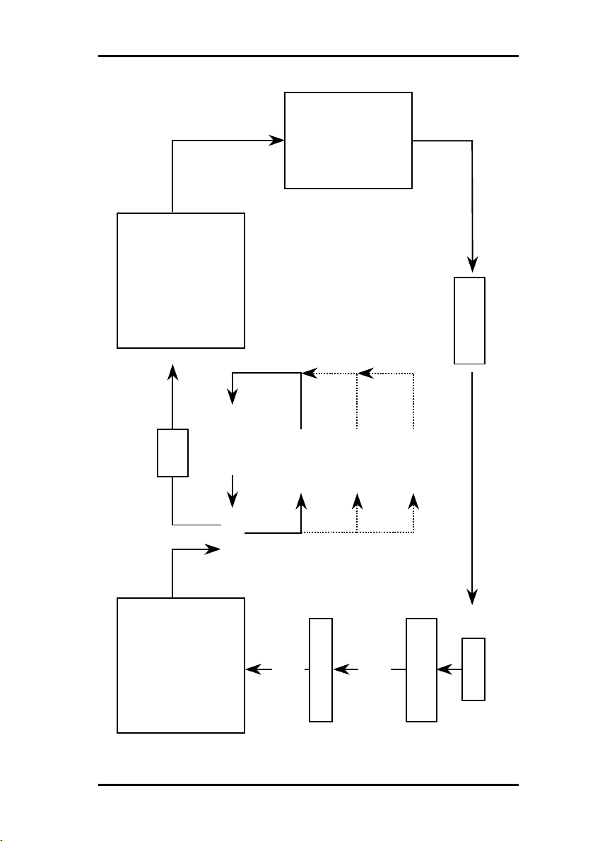
Job and entry in the chart
The following drawing has been prepared functionally, now person-related. It is therefore possible that several functions are simultaneously carried out by one person:
20 RW-470 CLIENTS
PROGRAM
PROGRAM SEQUENCE
PROGRAMPROGRAM
Plotter
RW-470
as required change of
- priority
- format
- medium
- copies
RW-470 PLOTBASE
- margin
completed job
LAN
SSL file
entry 1
entry 2
entry x
job
create
e.g.
- control view
- priority
- format
- medium
- copies
- margin
RW-470 PLOTCLIENT WIN
includes
drawin gs
drawings by
drag & drop
hand over
job creator
draftsman
engineering
RW-470 CLIENTS 21
customer
TOOLS
Tools
This section gives you a brief overview of the program’s tools.
You can blank out and insert the toolbars using the menu item
“view“. You work in the job editor with the main symbol bar, and
use the icon bar for the file preview.
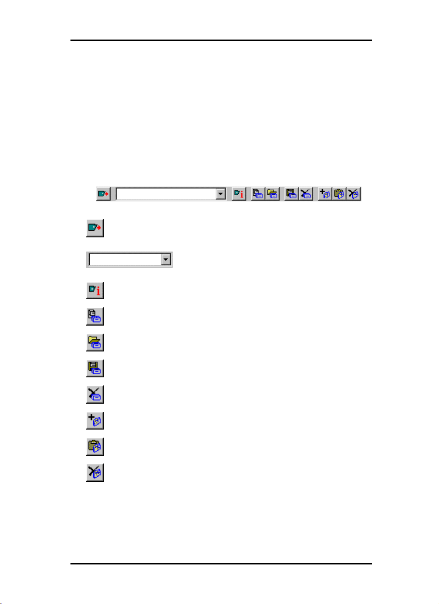
Main symbol bar
Send job to the SSL spool folder
View and selection of the SSL spool path
Open view information for the current plotter
Open new job
Open existing job
Backup job
Delete job
Attach entry in entry list
Insert entry in entry list
Delete entry from entry list
22 RW-470 CLIENTS
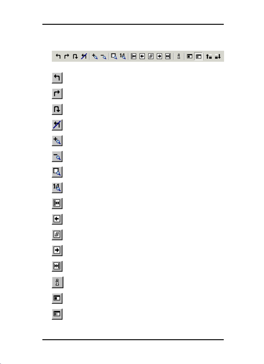
Icon bar
Rotate drawing 90° to the left
Rotate drawing 90° to the right
Rotate drawing through 180°
Drawing in original position
Successively enlarge drawing
Successively reduce drawing
Switch drawing to zoom all
Switch drawing to view 1:1
TOOLS
TOOLS
TOOLSTOOLS
Multipage document: View first page
Multipage document: Back one page
Multipage document: Enter destination page
Multipage document: Forward one page
Multipage document: View last page
Open file information
Display drawing in black & white view
Display drawing in preview in gray tones
RW-470 CLIENTS 23

TOOLS
Display drawing in preview lighter,
if gray display – has no effect on printing
Display drawing in preview darker,
if gray display – has no effect on printing
24 RW-470 CLIENTS

Presets
Before you begin with the work in RW-470 PLOTCLIENT WIN,
you must first set a few presets as e.g. determine the SSL paths
or enter the SSL default values.
Setting the SSL defaults
Setting of the SSL default values is automatically called up following installation, in the very first program start. Enter which
values are to be the standard values for all SSL print jobs. Also,
after the first program start, these default values can be changed
whenever you wish. Simply open the job editor via the menu
item “settings - SSL default“.
A detailed description of the possible settings is given in Chapter
“job editor“ from Page 30.
“General“ tab
The “General“ tab is opened via the menu item “Settings - Options“.
RW-470 PLOTCLIENT WIN takes the information on the directories, which you entered during installation and enters it in the
relevant fields:
PRESETS
RW-470 CLIENTS 25

PRESETS
• Working directory:
This is the folder, in which RW-470 PLOTCLIENT WIN temporarily caches the jobs, before they are finally sent to the folder that
RW-470 PLOTBASE looks through for jobs. The working folder
should always be a local folder, so that the program can quickly
access the data. This folder is in the two following fields: “SSL
spool path from the view of RW-470 PLOTCLIENT“ and “SSL
spool path from the view of RW-470 PLOTBASE“. The default
setting is automatically preset after installation of PLOTCLIENT.
Spool-path
• Universal Naming Convention:
:
::
The Universal Naming Convention guarantees a uniform view of
the path details from all the computers connected to your network. If you activate this option, you only need to filly out the
field “SSL Spool path“.
• SSL Spool path:
If you want to enter the path name under consideration of the
UNC, you only need to enter the folder for print jobs here. Enter
the folder exactly as it is to be found in you in-house network.
You can set up several SSL spool paths here, so that you can select the current path to be used from several paths.
• Compress all Plots to this Path:
The RW-470 PLOTCLIENT WIN can compress your jobs. To do
this, activate the left-hand option, “Compress all jobs...” above
the two “SSL-Spool path“ details. Your jobs will be automatically
compressed in zip Format.
If you want to send more than one job, you can also collect the
jobs in one zip file. If you want the path displayed after sending
a print job, in which the zip file is, activate the view of the “ZIP
path“ on the “formats“ tab.
• Collect jobs in one archive:
It often happens that you not only want to send one single job by
e-mail – as described above, but have several different print
jobs. To be able to send more than one print job in only one file
via e-mail, RW-470 PLOTCLIENT WIN can compress all jobs in
one single file, which is stored in zip format.
26 RW-470 CLIENTS

To do this you must activate the option “Collect jobs in one archive” above the two “SSL Spool path“ specifications. This option
can only be activated when “path for compressed jobs“ has
been activated.
If you want the path displayed, in which the zip file is cached,
activate “Show ZIP path after plot“ on the “format“ tab.
• SSL Spool path as PLOTCLIENT sees:
Here you set the folder, in which RW-470 PLOTCLIENT WIN
sends the jobs for RW-470 PLOTBASE. As the two programs
usually work together via the network, the folder for RW-470
PLOTCLIENT WIN lies on another drive than is the case RW-470
PLOTBASE. If RW-470 PLOTBASE works locally on C:\, this Cdrive is a drive letter e.g. between E and Z for RW-470
PLOTCLIENT WIN.
• SSL Spool path as PLOTBASE sees:
Here you have to enter the plot path, as RW-470 PLOTBASE sees
the path. As RW-470 PLOTBASE and RW-470 PLOTCLIENT WIN
work together via the network, there will be different drives.
Set up SSL spool paths
If you have several devices or types of software in the in-house
network for printing you can set up the corresponding SSL spool
path here for all these possible print outputs. Proceed as follows:
1. Open the “plot path“ window by clicking once on the button
to the right of the path information.
2. Click once on the “New” button and in the lower row “UNC
plot path“ enter the path:
PRESETS
RW-470 CLIENTS 27

PRESETS
3. Click on “Set“ if you want to enter several paths consecutively
or on “OK“ to quit the plot path input.
You can obtain information about the print job recipient connected with the selected SSL spool folder by clicking on the following info button once:
28 RW-470 CLIENTS

“Format“ tab
Open the “Format“ tab via the menu item “Settings - Options“.
On this tab you set the size unit that is to apply for all work with
RW-470 PLOTCLIENT WIN. You can choose between “Pixels“,
“Millimeters“ and “Inches“. The current valid size unit is always
displayed in the status row at the lower edge of the screen.
“[600 DPI]“ shows that 600 DPI is the standard value in RW-470
PLOTCLIENT WIN and all conversions in a conversion of size
units always refer to 600 DPI.
After each print job you can also have displayed, where the program has filed the compressed files:
Read in the previous chapter “General“ tab how you can automatically receive your print jobs from RW-470 PLOTCLIENT WIN
compressed. The “General” tab describes how to make the necessary settings.
PRESETS
If you have switched off renewed view of the message and want
it displayed again later, activate “Show ZIP Path after plot” on
the “Format“ tab.
RW-470 CLIENTS 29

JOB EDITOR
Job editor
In the job editor you can change the settings for jobs and the
entries included in them. Furthermore, you can also delete jobs
or entries.
The individual possible settings range from the format size to the
selection of the print medium and the output shaft through to
details of the position of the drawing header.
“Job” tab
On the “Job“ tab all entries that the user has made in RW-470
PLOTCLIENT WIN automatically appear. You can change these
details:
• Job Name
This is the name of the plot job that the user has chosen.
• User Name
In this field the name of the employee who collated the plot job
and sent it for printing is displayed.
• Customer
Here you can enter the name of the customer, for whom the job
is carried out.
30 RW-470 CLIENTS

JOB EDITOR
• Account
In this field the account number of the client is entered. This can
be an account number, which you assign in-house or the receiver of the invoice in-house.
• Notes
This field is free for your notes. You can enter up to maximum
60 characters. Please do not use any quotation marks.
• Distribution
In this field you enter which persons are to receive a copy of the
job. You can enter up to maximum 60 characters. Please do not
use any quotation marks.
• Collate
Activate this field if the plot job is to be printed out collated.
Collated means that the entries of an order are printed out as
follows when several copies are required:
E.g. you have the entries A, B and C. Three copies of each are to
be produced. With activated sort (“ON“) the print outs are in the
sequence A, B, C - A, B, C - A, B, C. If the printout is not sorted,
the complete number of entries are printed out: A, A, A - B, B, B
- C, C, C.
• Priority
This shows what priority the job has been given by the user:
Wait, Low, Normal, High. You can alter the priority here or set it
to the highest level.
• Job Copies
Here you can enter the number of job copies.
• Job Flag Sheet
Activate the “ON“ field, if you want an overview of all the information that you have entered in this “Job” tab printed out on a
cover sheet. You can add further information in the comments
field below this, which may not have more than a maximum 256
characters. Please do not use any quotation marks.
• Plotter
This default cannot be changed. The RW-470 plotter is preset.
RW-470 CLIENTS 31

JOB EDITOR
• e-mail
Use of the email function must be switched on in the presets. To
be able to use the email function, Microsoft® Outlook must be
installed. Furthermore “Internet Mail“ should be installed.
Here you can instruct the program to automatically send an email or a message to the user following successful job completion. To send an email, enter the email address of the user.
• Sample Print
Activate this option, if you want to check the quality of a print off.
Only the first set of copies will then be printed. The print off of
further sets of copies is stopped, so that you can check the quality of the print off. Then you will be asked, whether you would
like to continue with the print out or abort.
• Output
In the list field, you are offered two options for the print output at
the plotter: front and rear. If a folder has been connected, the
rear output is to be chosen for the folder. Otherwise the plot is
issued at the front.
• Locked Print
If you have important print jobs, which others should not be able
to see, activate the “Security“ option. Your job can then not be
viewed in RW-470 PLOTBASE by any other person. In the RW470 PLOTBASE it only has the status “Password“. Print jobs secured in this way can only be printed out by you entering the
password, which you have set here in RW-470 PLOTCLIENT
WIN. The job is automatically deleted immediately after it has
been printed.
• Delete
If you activate this option, the job is deleted again by RW-470
PLOTBASE immediately after printing.
Default settings area
The following chapters explain which default settings you can set
for the entries. The default settings only apply for new entries to
be added. The previous settings apply for the older entries.
32 RW-470 CLIENTS

JOB EDITOR
“Default Specific“ tab
On the “Default specific“ tab you enter the basic setting for all
new entries of a job.
Note: All basic settings apply for newly added entries
except for the number of copies.
• Formats
In this section of the tab you select the drawing format, in which
the drawing is to be printed. Apart from the “Original“, “Window“ and “Percent“ options, you will also find the drawing formats, which are the usual standards in Germany, all Europe and
in the USA: ISO A/B/C, ANSI A-E and ARC A-E.
In the format setting “Original“ the program obtains the format
size from the original file of the drawing. This is the presetting.
If you use the format setting “Window“, you can freely set the
values for the format width and format height, whereby the style
sheet is set by the window value. The freely settable settings refer
both to the alignment as well as the format size and the format
margin:
RW-470 CLIENTS 33

JOB EDITOR
Scale DX format width
Scale DY format height
If you want to scale the drawing smaller, set the format to “percent“. In this case the “Scaling” input field becomes active and
you can enter a value between 1.00 and 999.00.
If you choose one of the standard formats ISO, ANSI or ARC,
you can accept the dimensions or freely change them according
to your requirements:
You can use the “Window“, if you set a standard format e.g. ISO
A0 and want to extend the format width and format height. First
set the required format and then click in “Window“. You can now
change the “Scale DX“ and “Scale DY“ values to meet your requirements.
The value x in the “Maintain ratio“ window represents the side
proportions “width = x · height “. If you activate the “Maintain
ratio“ option, you can only alter the values above it for the width,
i.e. the Scale DX. The Scale DY, or height is then adjusted automatically, i.e. the drawing is scaled proportionally. This can be
useful e.g. if you know that the printout of a drawing is too large
for the paper size available. In this case, activate the “Maintain
ratio“ option and reduce the value slightly, to obtain a proportionally correct printout. The “Maintain ratio“ option is already
activated as a standard setting.
• Scaling
The X-scaling input field only becomes active if you have selected
the “Percent“ format. Thus you can print off the drawing in a free
format of 1.00 % to 999.00 % of the original. The Scale DY input
field is automatically filled with the value of the Scale DX, if you
have activated the “Maintain ratio“ option. If you then want to
enter the Scale DY value independently, you must deactivate the
“Maintain ratio“ option. In this case, you must consider that the
drawing will be distorted.
• Media type and position
Use this menu to select which type of media the drawing is to be
printed on: Any, Paper, Transparency or Film. The selection depends on what roll of medium you have fed in the plotter. The
“Position“ field is used to set the symbolic position on the paper
34 RW-470 CLIENTS

JOB EDITOR
if the image is to be printed on a larger paper format. E.g. if you
have a ISO A4 drawing, which is printed in original size on ISO
A1, you can fix here where the drawing is to be positioned on
the larger sheet.
• Cut Mode
The selections available is “Format“. If don´t activate “Format”,
the plotter cuts the drawing immediately after the last data has
been printed, it means synchronous. This results in optimum paper or medium use, because it produces the smallest amount of
waste.
On the other hand, if you want the printout to always be cutted
to a standard format, no matter how much space remains unprinted, activate “Format“. The plotter then always cuts to the
next largest format. This can be a disadvantage if e.g. a drawing
is only around 0.5 cm larger than a ISO A5 page is printed on a
ISO A4 page and thus almost 50 % of the sheet remains unused.
The advantage is that some folders require exact formats and
you can match them using the “Format“ setting.
• Copies
You can enter any number of copies between 1 and 999 to be
printed by the job .
Note: The number of copies is not the default for newly
added entries
• Title block
As many folders expect title blocks in different positions, you can
alter the title block to match the folder to ensure that it is on the
top after folding.
If you do not know the position of the title block, you can activate
the drawing header symbol using the question mark. The folder
then automatically uses the optimum folding format for the
folder. If you know the position, activate one of the four possible
title block positions:
RW-470 CLIENTS 35

JOB EDITOR
Position of the title block unknown, i.e. there is
no optimized folding of the drawing
Title block in the top left-hand corner
Title block in the top right-hand corner
Title block in the bottom right-hand corner
Title block bottom left-hand corner
With this setting, you inform RW-470 PLOTBASE, on which side
the title block is located. The program then rotates the drawing
into the position required for the folder.
Attention: This setting refers to the original position of
the drawing in the preview window. The drawing can
be rotated to its original position by clicking on the
button shown below. As soon as the original position is
displayed, the symbol is deactivated:
• Rotate
Here you can say whether the drawing is to be rotated or not
during plotting. Rotations of 0°, 90°, 180° and 270° are possible.
When set to “Auto“, RW-470 PLOTBASE rotates automatically if
this results in less waste paper
36 RW-470 CLIENTS

JOB EDITOR
• Border
If you want a white border around the drawing, activate the
“ON“ field and enter the required spacing for all side borders.
The current dimensional units are given in the status bar at the
bottom of the screen.
• Media Source
Here you can select the trays in which the rolls with the different
Printing materials (paper, transparent, etc.) are located. They
can also have varying widths.
If you select the “Automatic“ setting, the plotter chooses the input
tray, which matches the format size of the drawing. Should this
input tray be empty, the plotter uses the tray (roll) with the next
largest format.
• Invert
If you activate this option, the drawing is inverted, i.e. black and
white colors are swapped.
“Default Additional“ tab
The “Default additional“ tab is used to enter mirroring, stamping
and pen details.
The stamp editor and the pen settings (Calcomp, HPGL) are
each explained in their own chapter. Please read the separate
“Stamp editor” section at the end of this Chapter from Page 40
ff. and the separate chapter on “Pen settings“ from Page 47 ff.
RW-470 CLIENTS 37

JOB EDITOR
• Mirror
In this area you can set whether the drawing is to be mirrored or
not during plotting. The individual fields mean the following:
OFF: The drawing is not mirrored during plotting.
X: The drawing is mirrored horizontally.
Y: The drawing is mirrored vertically.
XY: The drawing is mirrored about both axes simultaneously;
equates to a 180° rotation.
You usually use these settings if the drawing has been scanned
and saved with a mirror inversion. This is especially important if
a transparency has been scanned with mirror inversion to increase the contrast.
“Entry“ area
You can read here, which adjustments can be made for an individual entry.
If you want to alter the settings for the individual entries i.e. alter
the drawings, you can do this on the two “Specific“ and “Additional“ tabs, which can be used to make the same adjustments
as described in the “Defaults“ tabs.
To begin altering the settings of an entry you must mark it in the
left-hand entry list. The “Specific“ and “Additional“ tabs are then
opened and can be edited. If you want to change back to the job
settings or defaults, click once on the “Job“ or “Defaults“ button
above the entry list.
38 RW-470 CLIENTS

JOB EDITOR
If you want to make entries in the “Specific“ tab, read the information given for the “Default Specific“ tab from Page 32.
If you want to alter the settings on the “Additional“ tab , read the
details for the “Default Additional“ given on Page 37.
You can open a tab for the pen settings on the “Additional“ tab.
To do this, click on the “Pen settings“ button. When an entry or a
drawing is marked, the program automatically identifies the
format and opens the Calcomp or HPGL settings itself. Please
read the separate sections on the pen settings for Calcomp pens
from Page 55 and the HPGL pens from Page 48.
The main task with RW-470 PLOTCLIENT WIN is to collate plot
jobs for RW-470 PLOTBASE. You are free to choose whether you
compile a job with one entry or with several entries. The way of
compiling jobs will be explained in the separate chapter „Collate
jobs“ on page 61.
RW-470 CLIENTS 39

STAMP EDITOR
Stamp editor
The stamp settings can be altered on two levels. To configure a
stamp for an individual entry, select the “Additional“ tab under
“Entry“. Now click on the “Settings” button under “Stamp“. The
same button can be you in the “Defaults“ area on the “Extended
Defaults “ tab. The settings in the “Defaults“ area are basic settings, in which the following must always be noted:
Note: Changes to the basic settings always only apply
to new entries that are added. Entries already included
in a job retain their settings.
In stamp editor you have two tabs in which you can alter settings.
These are the “Settings“ and “Data“ tabs. You can define as
many stamps as you like per drawing.
Make stamp
This chapter describes how you can name and save new stamps.
Proceed as follows to configure a new stamp:
1. The first stamp entry is preliminarily named “000“. Click on
the following symbol to edit the stamp name:
2. You can now delete the existing name entry and enter your
own name for the first stamp.
3. Now you can either enter your own settings for the stamps,
as described in the following chapters or use an existing
stamp configuration. To do the latter, click on the “Open“
button under “Configurations“. Now select a configuration
that you have saved previously (read the following chapter
“Stamp Configurations“) from the file selection. Now save
40 RW-470 CLIENTS

STAMP EDITOR
this configuration for the defaults or the entry by clicking on
the button with the same name; i.e. “Save“. This configuration is now saved under the marked stamp name in the
“Select Stamp “ window.
4. You can produce as many stamps as you wish for a draw-
ing. If you now also want to configure an additional new
stamp, click on the following button:
5. Enter a name and set the desired configurations, as already
described under Step 3.
Stamp configurations
The stamp settings are usually saved for specific entries. This
means that these settings only apply for one entry or a limited
number of entries. However, you can also backup a stamp configuration in its own “Stamp File“. It can then be used at any time
for producing a new stamp, which you would like to use for
other entries.
The stamp files have the file extension [*.stp] and it is advisable
that this extension is always retained.
Should you want to call up the configuration, you must use the
“Open“ button. The “Open“, “Save [as]“ or overwrite old stamp
files steps are the same as those used in general file management.
Edit or delete stamp
If you want to make changes to the stamp configurations produced, first click on the correct stamp in the “Select stamp “ window and then change the settings. If you now change to another
stamp or close the window by clicking on “Ok“, all the settings
are saved.
RW-470 CLIENTS 41

STAMP EDITOR
To delete a stamp, first mark it and then delete it by clicking on
the following button:
“Settings“ tab
General details, e.g. on mirroring, rotation, stamp type and
stamp position are made in the “settings“ tab:
• Mirror
The standard orientation of the text is always the reader direction. You can mirror the text here in four ways:
None: The text is not mirrored and is in the reader direction.
X-mirror: The text is mirrored horizontally.
Y-mirror: The text is mirrored vertically.
XY-mirror: The text is mirrored about both axes simultaneously,
which equates to a rotation of 180°.
42 RW-470 CLIENTS

STAMP EDITOR
• Rotation
The standard orientation of the text is always the reader direction. Here you can alter the text rotation of in 1° steps.
• Stamp mode
The standard setting for the type of stamp is always “covering“.
There are three possible settings:
- Covering
The stamp overwrites the area of the drawing beneath it.
- Transparent
In the “Transparent“ setting the inserted stamp lies “beneath“ the
existing drawing, which means that parts of the stamp can be
overwritten.
- Inverting
It is only the “Inverting“ setting that allows both the drawing as
well as the stamp to be identified in the plot, because the overlapping areas are shown inverted.
• Stamp placement
This is where you fix the actual position of the stamp on the
drawing. The frame equates to the drawing, so that you can
choose from the entries for the nine positions from “top“, “centered“ to “bottom“.
In addition, you can shift this fixed position in the field to the
right of it by a valid size unit. You set the currently valid size units
for RW-470 PLOTBASE in the configuration program and it is
displayed at the bottom of the screen in the status bar.
• Scale position
With the “Scale position“ you determine whether the stamp always retains its position relative to the edge of the drawing when
the size is changed or whether the distance to the edge of the
drawing should be scaled too.
• Stamp all pages
If you are editing a Multipage document, i.e. a job order contains several drawings, you can fix here whether all the drawings
are to be stamped.
RW-470 CLIENTS 43

STAMP EDITOR
• Frame
Activate the “Enable frame“ field if you want a stamp frame to
be printed. Three default settings can be set for the stamp frame.
Here too, the settings refer to the currently valid size unit, which
you can see in the status bar:
Upper setting - stamp border: With the upper of the three settings you set the distance of the stamp to the edge of the drawing.
Middle setting – Stamp content: The middle setting gives the
distance of the stamp content to the stamp frame.
Lower setting. The lower setting is used to fix the thickness of the
stamp frame.
“Data“ tab
On the “Data“ tab the user specifies the stamp text and logo.
You can also change the text and text attributes on this tab or
even change the logo:
• Stamp type
Before you can begin to enter the settings or change the other
fields, you must first select the stamp type, whereby the two symbols are clear: With the “A“ you activate the “Text“ field, with the
44 RW-470 CLIENTS

STAMP EDITOR
colored symbol you let the program know that there is a logo
and activate the “Logo orientation“ field.
• Text
In this text field you can enter the text to be “Printed“ with your
stamp. In the text field you can edit in the same way as in common word processing programs. Change lines be entering return [
↵ ], you can jump to the start and end of the rows using
the “Home“ and “End“ keys, and if your text is very long, use the
“CTRL + Pos1“and “CTRL + End“ keys to move to the first or last
rows respectively..
• Font
The “Font“ button opens the usual WINDOWS dialogue for the
font attributes. Only the font color setting does not have any effect, because the color is fixed in RW-470 PLOTCLIENT WIN with
black.
• Preview
Use the “Preview” button if you want to view the stamp again
before the final print. In this window you can move the directional arrows to move from side to side and enlarge or reduce
the view using “+“ and “–“. The left-hand mouse button can be
used to enlarge a selected area.
However, the preview only applies to the stamp itself and the
arrangement of its logo and its text. The preview does not show
you the stamp’s position on your drawing, which you set on the
“settings“ tab!
• Macros
You can use a macro to enter a text field, which is not filled out
until printed. In the preview you can only see the field function.
All the file details always refer to the drawing or the entry on
which the stamp(s) are printed. The following macros are available:
- User defined: You can use this macro to issue the text that
appears in the registry path “Software - RW-470“ for the
“Custom label” key produced by you.
- User name: The user name gives the user, who carried out
the stamp function.
RW-470 CLIENTS 45

STAMP EDITOR
- Computer name: The computer name is the PC at which the
stamp was inserted.
- File name: This macro inserts the whole file name of the
drawing or the entry, including the path and prints it on the
drawing.
- File title: This macro only gives the actual file name of the
drawing or of the entry without the path details.
- Date: With this macro, RW-470 PLOTCLIENT WIN inserts the
current date of the print.
- Consecutive number: This macro is suitable if you have lots
of drawings or entries with the same stamp text and you
want to differentiate between them by numbering them. If
you want to have a consecutive number printed on the plot,
you must enter the first number under “Enumeration“.
- Path: This macro only gives the path of the drawing or the
entry without the file name.
- SSL commands: Precise information about the SSL com-
mands is given in the appendix to this manual.
- Time: This macro inserts the time the drawing was stamped.
• Text color
As black is the only color available in this version of RW-470
PLOTCLIENT WIN you cannot alter any settings here.
• Start count at
If you have selected the field function “Consecutive number“ as a
macro, you must enter the first number here
• Logo
Select a graphic using the “Browse“ button, which is to appear in
the stamp as a logo. For example, your firm's logo. The file formats that can be used are: BMP, Calcomp, CALS, CGM, CIT,
EPI, EPS, HPGL, HPGL/2, HPGL-RTL (b/w), PCX, PDF, RW-470
PS, RLC, TG4, T6X and TIFF G4. You can select from four possible positions for the logo relative to the text: above, below, right
or left of the text. Select a position by clicking on it.
46 RW-470 CLIENTS

PEN SETTINGS
Pen settings
You can change the pen settings on two levels. On the one hand
in the “Defaults“ area of the “Extended defaults “ tab and on the
other in the “Entry“ area on the “Additional“ tab. The settings in
the “Defaults“ area are basic settings, for which the following
must always be noted:
Note: Changes to the basic settings always only refer
to new entries that have been added. Existing entries
already in the job retain their settings.
You can only change pen settings if the entry has either a
HPGL/2 or Calcomp file format. There are three tabs each for
both file formats, on which you can change the settings. These
are the “Pens“, “Colors“ and “General“ tabs.
In the “Defaults“ settings you must use the separate “Calcomp
settings...“ and “HPGL settings...“ buttons, because a job can
contain several drawings with different formats.
If you alter the settings for an entry, RW-470 PLOTCLIENT WIN
immediately identifies the format and automatically opens the
respective HPGL or Calcomp tabs via the “Pen settings...“ button.
View the changes
RW-470 PLOTCLIENT WIN provides you with an additional function, which allows you to look at the changes to the pen sizes
and some of the pen colors before printing in the preview file, if
changes have been made to a certain entry. To do this, proceed
as follows:
1. Activate the view using the “View - Preview file“ menu item.
2. Mark an entry in the entry list.
3. In the job editor change to the “Additional“ tab and open
the “pen settings...“.
RW-470 CLIENTS 47

PEN SETTINGS
4. Make your changes.
5. Now change to the “General“ tab and activate the pen
source as “user“.
6. Quit the pen settings.
7. Double click on the entry that has just been changed.
The changes are visible in the file view. You may have to enlarge the view if e.g. the pen widths have only slightly
changed.
Note: It is possible that if you change colors you will
not see any large changes in the preview file, if you
only change from 50% gray to 60% gray for gray
shades say. Clear changes are e.g. visible if you set the
color of all pens to “White“, but then you don’t have to
print the drawing either!
HPGL/2 - Pens
The pen attributes are set in the “Pen“ tab:
48 RW-470 CLIENTS

PEN SETTINGS
• Pen size
Enter the pen size directly in the first column under “Size” using
the keyboard. The maximum values that you can enter depend
on the size unit, which you set in the configuration program. The
current valid size unit is given in the status bar at the lower edge
of the screen.
If you want to “Switch off“ a pen, you can enter the pen widths
as “0“or set the pen color as “White”.
• Pen colors
Select the pen color in the second column under “Color“. Click
on the arrow to the right of the color setting and drag the mouse
to the desired color. If you want to “Switch off“ a pen, you can
enter the pen color as “White“ or the pen widths as “0“.
The individual pen color should only be considered as being a
“symbolic equivalent“ for a gray scale value. Each color is
equivalent to a %-value of gray: thus e.g. “yellow“ could be
represented by 10 %-Gray, “red“ with 50 % gray and “blue” with
80 %- gray etc. You can set which gray scale a color represents
on the “Color“ tab.
If the plotter is definitely to use the pen attributes from the entry’s
corresponding SSL file, you must activate the “File“ field on the
“General” tab as the pen and/or color source.
• Grey (%)
The gray scale can only be adjusted if you have chosen “Gray“
as the color. The changes are also made directly using the keyboard.
• Fill
With “Fill“ the program offers you a comfortable way of simultaneously setting the attributes for all 256 pens. First set the pen
widths, the pen color and the gray scale and then click once on
“Fill“:
RW-470 CLIENTS 49

PEN SETTINGS
HPGL/2 - Colors
To assign the required gray scale to each of the individual colors, open the “Colors“ tab:
In this window you can change the gray scale, which has been
assigned to each color. If you do not want to change each color,
you can set all pens to “Gray” on the “Pens“ tab and there you
can set the individual gray values for each pen.
You can change the percentage value directly using the keyboard. Click on “OK“ to quit the window and your settings are
saved. If you do not want to save your changes, quit the window
with “Cancel“ or “ESC“.
50 RW-470 CLIENTS

PEN SETTINGS
HPGL/2 - Misc
• Pen Source:
If you activate the “File“ field you instruct the plotter to use the
pen width details when plotting, which are entered in the entry’s
SSL file and that it should not use the settings in the “Pens“ tab. If
no pen widths have been defined, the program uses your settings.
If you activate “User“, your settings are always used.
• Color Source:
If you activate the “File“ field, you instruct the plotter to use the
pen color information when plotting, which are entered in the
entry’s SSL file and that the settings on the “Pens“ tab are not to
be used. If no pen colors are defined, the program uses your
settings.
If you activate “User“, your settings are always used.
• Pen Scale:
Activate the check box, if the pen widths are to be scaled with the
drawing. To avoid possible loss of information during the printout, you must ensure that you have entered at least one minimum pen width in “Pen settings“ if the drawing is to be reduced
RW-470 CLIENTS 51

PEN SETTINGS
in size and at least one maximum pen width if the drawing is to
be enlarged
• Clipping:
The clipping command removes the white edges on the border
of the drawing. Most plotter languages differ from each other in
many ways to a greater or lesser extent – including with respect
to the section, which, put simply, refers to the paper size.
This fact means that undesirable printing results are obtained, if
a drawing is only printed in sections or in the most unfavorable
case a white sheet of paper comes out of the plotter.
The “Clipping” function is considered in the context of the widely
used reference plotter “HP DesignJet 650 C / C 2859b“: If you
activate the check box, the drawing is printed in exactly the same
way as it was printed on the “HP DesignJet“ plotter. However,
undesirable printing results can result, if the plotter language of
your plotter differs greatly from that of the “HP DesignJet“.
If you deactivate the function, RW-470 PLOTCLIENT WIN looks
for the drawing dimensions itself and thus guarantees that the
whole drawing is plotted.
• Ignore pen width
You can only activate this option if you have not activated the
“clipping“ option.
Activate the option, e.g. in case of a drawing that is exactly ISO
A4 size to guarantee that it is printed on an A4 sheet and not on
a printout with the next format because the pen widths are too
large and the A4 format is slightly exceeded, causing unnecessary wastage.
In all cases where a drawing has exactly the same size as a
standard formats, you can ensure that this drawing is printed off
on this format and thus avoid unnecessary waste paper.
• Pen Limits (mm)
− Min
Using the keyboard, enter the minimum pen widths. The entry
here affects all HPGL pens.
As there are plotters in which even at the finest resolution the individual pixels are not reliably reproduced, a minimum pen size
is indispensable in these cases.
52 RW-470 CLIENTS

PEN SETTINGS
Should one of your settings not cover the plotter circumstances
and no longer guarantee the printout of a drawing object, RW470 PLOTCLIENT WIN automatically adjusts the pen widths.
− Max
Using the keyboard, enter the maximum pen widths. The entry
affects all HPGL pens.
Analog to the problem with the minimum pen widths, you can
set the maximum thickness that the pen draws, e.g. to prevent
the drawn objects from overlapping when printed. Setting the
maximum pen widths on the other hand is less seldom necessary.
Should one of your settings not cover the plotter circumstances
and no longer guarantee the printout of a drawing object, RW470 PLOTCLIENT WIN automatically adjusts the pen widths here
too.
• Steps/cm
Some time ago, most plotters had stepper motors, which ran at a
varying number of steps per centimeter. In the meantime, the
standard is 400 steps per centimeter. The RW-470 PLOTCLIENT
WIN therefore enters 400 as a default value, which does not
normally have to be altered. Nevertheless, it is sometimes advisable to ask the customer what step number per centimeter they
are used to working with to guarantee plot consistency. Furthermore, it can be necessary to make a change to reduce the DPI,
to release more system memory for large drawings:
Attention: If you enter a larger value, you will obtain a
s m a l l e r drawing: The entry 1 equates to 0.25 %. Example: if you enter 401, the drawing is reduced to
99.75 %.
• HPGL Font path
Here you inform the program, in which folder the fonts are to be
used when printing HPGL files.
RW-470 CLIENTS 53

PEN SETTINGS
• Dither mode / RTL
Here you can select gray value patterns for bitmap graphics. You
can choose between the gray value patterns “Symmetric pattern“
or “diffusion pattern“. Test them and see which pattern best suits
your graphic. To do this, you have to reload the drawing in the
preview file after each change.
• Pattern Style
There are four fill patterns that you can use to influence a vector
graphic.
“Round“ means that a certain colored area is filled with a certain
number of filled circles, which are given a certain arrangement
on the area, to achieve the intended color saturation.
In “Random“ on the other hand a percentage of color saturation
is determined for the same colored area, which is then converted
into the necessary number of pixel, which are randomly arranged over the area to achieve the intended color saturation.
Which is why that when circle patterns are overlapped, the covered areas cannot be as clearly identified as if two random patterns are overlapped. The recommended default setting is
therefore “Random“, because you can achieve the best results.
As the “Round“ setting has been installed as a standard to date,
this option has been retained of you do not see the need to print
the same drawings differently in future.
In addition, you can also select the gray value patterns “Symmetric pattern“ and “Diffusion pattern“. As the name suggests,
the “Symmetric pattern“ produces a symmetrical gray value pattern. If you select the “Diffusion pattern” as the gray value pattern, a pattern is loaded. Try and see which pattern produces the
best printing results.
54 RW-470 CLIENTS

PEN SETTINGS
Calcomp - Pens
The pen attributes are set on the “pen“ tab:
• Pen size
The pen sizes are entered directly using the keyboard in the first
column under “Size“. The maximum values that can be entered
depend on the size unit, which you set in the configuration program. The current valid size unit is shown in the status bar at the
bottom of the screen.
If you want to “Remove” a pen, you can set the pen widths as
“0“ or as the pen color “White“.
The standard values for the pen widths of the 16 Calcomp pens
are given in the technical manual (Chapter “Calcomp commands and pens“).
• Pen color
Select the pen color from the second column under “Color“.
Open the pull down menu and select the required color. If you
want to “remove“ a pen, you can set the pen color as “White“ or
the pen widths as “0“. You can set the gray shade that a color
represents on the “Colors“ tab.
• Grey (%)
The gray scale value can only be adjusted if you have selected
“Gray“ as the color. Here too the changes are made directly using the keyboard.
RW-470 CLIENTS 55

PEN SETTINGS
• Fill
The “Fill“ option allows you to set the pen attributes for all 16
pens simultaneously. To do this, first set the pen widths, the pen
color and the gray scale value and then click once on “Fill“:
Calcomp - Colors
To assign the required gray scale value to each individual color,
open the “Color“ tab:
The change to the percentage figure is made directly using the
keyboard. Quit the window with “OK“ and your changes will be
saved. If you do not wish to save your changes, quit the window
with “Cancel“ or “ESC“.
In this window you can change the gray scale value, which has
been assigned to each color. If you do not want to change each
color, you can set all pens to “Gray” on the “Pens“ tab and then
set the individual gray values for each pen.
56 RW-470 CLIENTS

PEN SETTINGS
Calcomp - Misc
• Pen Source
If you activate the “File“ field, you instruct the plotter to use the
pen width information in the entry’s SSL file when plotting and
not the settings from the “Pens“ tab. If no pen widths are defined, the program uses your settings.
If you activate “User“ your settings are always used
• Pen Scale
Activate this field if the pen widths are to be scaled at the same
time as a drawing is scaled. To avoid the possible loss of information when printed ensure that have set at least one minimum
pen width if the drawing is to be reduced in size and at least one
maximum pen width, if the drawing is to be enlarged by scaling.
• Ignore pen widths
Activate this option, e.g. if a drawing is exactly the same size as
a ISO A4 sheet, to guarantee that it is plotted on an A4 sheet
and not on the next larger format because the pen widths were
too large causing the drawing to slightly exceed the A4 format,
thereby causing unnecessary waste paper.
In this way, you can ensure that a drawing that has exactly the
same size as a standard format is printed on this size paper
thereby avoiding an unnecessary waste of paper.
RW-470 CLIENTS 57

PEN SETTINGS
• Pen Limits (mm)
− Min
Enter the minimum pen widths using the keyboard. The information entered here affects all Calcomp pens.
As there are plotters in which even at the finest resolution the individual pixels are not reliably reproduced, a minimum pen size
is indispensable in these cases. Should one of your settings not
cover the plotter circumstances and no longer guarantee the
printout of a drawing object, RW-470 PLOTCLIENT WIN automatically adjusts the pen widths.
− Max
Using the keyboard, enter the maximum pen widths. The entry
affects all Calcomp pens.
Analog to the problem with the minimum pen widths, you can
set the maximum thickness that the pen draws, e.g. to prevent
the drawn objects from overlapping when printed. Setting the
maximum pen widths on the other hand is less seldom necessary. Should one of your settings not cover the plotter circumstances and no longer guarantee the printout of a drawing
object, RW-470 PLOTCLIENT WIN automatically adjusts the pen
widths.
• Step size/cm
Some time ago, most plotters had stepper motors, which ran at a
varying number of steps per centimeter. In the meantime, the
standard is 800 steps per centimeter. The RW-470 PLOTCLIENT
WIN therefore enters 800 as a default value, which does not
normally have to be altered. Nevertheless, it is sometimes advisable to ask the customer what step number per centimeter they
are used to working with to guarantee plot consistency. Furthermore, it can be necessary to make a change to reduce the DPI,
to release more system memory for large drawings:
Attention: If you enter a larger value, you will obtain a
s m a l l e r drawing: The entry 1 equates to 0.125 %.
Example: if you enter 801, the drawing is reduced to
99.875 %.
58 RW-470 CLIENTS

PEN SETTINGS
• Pattern Style
Three types of patterns are defined for Calcomp drawings, in
which the “Pattern“ command is used.
“Round“ means that a certain colored area is filled with a certain
number of filled circles, which are given a certain arrangement
on the area, to achieve an intended color saturation.
In “Random“ on the other hand a percentage of color saturation
is determined for the same colored area, which is then converted
into the necessary number of pixels, which are randomly arranged over the area to achieve the intended color saturation.
Which is why that when circle patterns are overlapped, the covered areas cannot be as clearly identified as if two random patterns are overlapped. The recommended default setting is
therefore “Random“, because you can achieve the best results.
As the “Round“ setting has been installed as a standard to date,
this option has been retained of you do not see the need to print
the same drawings differently in future.
Finally, you can also select the gray value pattern “Symmetric
pattern“. As the name suggests, the “Symmetric pattern“ produces a symmetrical gray value pattern. Try and see which pattern produces the best printing results for your graphic. To do
this you must reload the drawing in preview file after each
change.
• Synchronization
Synchronization is used to check the completeness of the Calcomp files, which have been sent from the application program.
Four pieces of information are used for the synchronization settings:
• Sync character
• End character
• Double Sync
• Test sum
You can either let RW-470 PLOTCLIENT WIN determine the values or you can enter the necessary settings yourself. If the program is to determine the values, activate “Auto detection“.
We recommend that you do not alter the standard values if you
want to enter the settings yourself. Should you nevertheless want
RW-470 CLIENTS 59

PEN SETTINGS
to make a change or to find out more on the topic, compare the
settings with those in your CAD system or read the following section in the “Calcomp Inc.“ manual:
“CALCOMP - ONLINE REFERENCE MANUAL“ in the section
“Data Message Format“.
The standard settings are:
Sync character: 2
End character: 0
→ [setting from 0 to 127 possible]
→ [setting from 0 to 31 possible]
Double Sync: OFF
Test sum: OFF
The following two examples serve as possible comparisons:
• AutoCAD12:
Sync character: 22
End character: 13
Double Sync: ON
Test sum: ON
• FordCAD:
Sync character: 2
End character: 3
Double Sync: OFF
Test sum: ON
60 RW-470 CLIENTS

COLLATE JOBS
Collate jobs
Your main task with RW-470 PLOTCLIENT WIN is to collate [Plot] jobs for RW-470 PLOTBASE. You are free to choose whether
you compile a job with one entry or with several entries.
You can prepare fully new jobs or open existing jobs and add
further entries.
To collate a new job you must proceed as follows:
1. Open a new job, either via the menu item “File - New“ or by
clicking once on the relevant button:
2. Assign a name to your new job.
Attention: The extension “*.ssl“ must be retained, so
as to guarantee that RW-470 PLOTBASE can recognize
the job.
3. Now you add new entries to the job. Your have three possible
options for adding an entry. Refer to the following section
“Add entries“.
4. As soon as you have included all the entries in the job, you
begin to enter the settings, which RW-470 PLOTBASE needs
to be able to print off the job as required. Please refer to the
chapter “Job editor“ from Page 30.
5. Finally, send the job to RW-470 PLOTBASE by either selecting
the menu item “File – Print SSL“ or by clicking on the relevant
button:
RW-470 CLIENTS 61

COLLATE JOBS
Add entries
Newly inserted entries can have the following file formats, which
are identified by RW-470 PLOTCLIENT WIN from the file extension:
• Calcomp [*.906, *.907]
• CALS MIL-STD 1840B,28002A [*.cal]
• DWG [*.dwg]
• HPGL/2, HP-RTL [*.plt, *rtl]
• Intergraph [*.cit, *.tg4]
• PCX [*.pcx]
• RLC [*.rlc]
• TIFF G4 [*.tif]
• Windows Metafile [*wmf]
• Windows OS/2 Bitmap [*.bmp]
The file formats CGM [*.cgm] as well as PDF and postscript, i.e.
RW-470 Postscript Level 3 Compatible Option [*.pdf, *.ps] are
available as an optional feature. The file format DWG can only
be used if AutoCAD (2000 or 2000i) is installed on RW-470
PLOTBASE server PC.
Add with button
To add an entry with the help of the button, proceed as follows:
1. Mark an entry in the entry list, before or after the place where
the new entry is to be inserted.
If you do mark an entry, new entries are always inserted at
the end of the list.
2. Click on the relevant button on the Entry toolbar. If the new
entry is to be inserted after the marked entry, click on:
If the new entry is to be inserted in front of the marked entry,
click on:
62 RW-470 CLIENTS

COLLATE JOBS
3. Select the required file, which has one of the above file for-
mats and confirm with “OK“. You can now mark several files
to insert lots of drawings in one go, as in the File Manager.
Add using the right-hand mouse button
To add an entry using the right-hand mouse button, proceed as
follows:
1. Mark an entry in the entry list before or after which the new
entry is to be inserted.
If you do mark an entry, new entries are always inserted at
the end of the list.
2. Keep the mouse cursor on the entry list and click the right-
hand mouse button:
3. If the new entry is to be inserted in front of the marked entry,
select “Insert“. If the new entry is to be inserted after it,
choose “Add“.
The program opens a file selection window.
4. Select the required file, which has one of the above file for-
mats and confirm with “OK“. As in Windows Explorer, you
can now mark several files to insert lots of drawings in one
go.
Add with menu item
To add an entry with menu item, proceed as follows:
1. Mark an entry in the entry list, before or after the place
where the new entry is to be inserted.
If you do mark an entry, new entries are always inserted at
the end of the list.
2. Select the relevant menu item from the “Edit” menu. If the
new entry is to be inserted after the marked entry, select:
Edit- add entry...
RW-470 CLIENTS 63

COLLATE JOBS
If the new entry is to be inserted in front of the marked entry,
select:
Edit – insert entry...
The program opens a file selection window.
3. Select the required file, which has one of the above file formats and confirm with “OK“. You can now mark several files
to insert lots of drawings in one go, as in the File Manager.
Add with Drag & Drop
To add an entry using Drag & Drop, proceed as follows:
1. Open Windows NT Explorer or File Manager and arrange the
two windows of RW-470 PLOTCLIENT WIN and Explorer or
File Manager so that they are positioned next to each other or
on top of each other.
2. Mark an entry in the entry list of RW-470 PLOTCLIENT WIN,
after which the new entry is to be inserted.
If you want to insert a new entry in front of an existing entry,
mark the entry in the entry list before the existing entry!
If you do not mark any entry, new entries will always be inserted at the end of the list.
3. Change to the folder in Explorer or File Manager from which
you want to fetch the new entry.
4. Click on the required file with the left-hand mouse button and
holding the mouse button pressed down, drag the file to the
file list of RW-470 PLOTCLIENT WIN. You can also add several drawings in one go as in Explorer or File Manager by
marking several files.
Add multiple entries
Sometimes, a customer job order is such that an entry has to be
printed several times with different settings: e.g. if an entry is to
be plotted once with A0 format on paper and the second time
with A1 format on a transparency. To do this, you can also add
an entry several times.
64 RW-470 CLIENTS

COLLATE JOBS
However, the program only physically inserts an entry once and
if you add an entry several times, it simply sets a reference to the
first entry.
Example: You insert the file “ABC.tif“. This file is to be printed in
format A0. For the second print out in format A1, insert the file
“ABC.tif“ a second time. At this moment, RW-470 PLOTCLIENT
WIN recognizes that there is already a file with the same name
in the entry list and only sets a reference to the already inserted
file.
This approach of the program has two particular advantages for
you. On the one hand it saves space on your harddrive, is the
files are very large and on the other hand, you cannot inadvertently insert a file with the same name but different content.
Delete entries
If you want to delete an entry from the list, use one of the two
following possible methods
1. Mark the entry in the entry list that you want to delete and
select the menu item “Edit – Delete entry “.
2. Mark the entry to be deleted and click on the following button
once:
To delete several entries you can also use the multiple selection
of entries. When selecting several entries in the entry list to delete, proceed exactly as before, as you are used to from Windows NT Explorer or File Manager: Either click with the mouse
on an entry and drag the mouse cursor down to the last entry to
be deleted and while keeping the mouse key depressed, where
the entries to be deleted are listed one after the other or use the
SHIFT- key. To mark several entries that are not listed one after
the other, use the Ctrl Key, as in Explorer.
RW-470 CLIENTS 65

COLLATE JOBS
After you have inserted or appended the entries, adjust the settings for the jobs and individual entries in the job editor. To do
this, read the following chapter.
Entry information
Before you can begin with a possible change to the settings, you
can view a summary of all the currently loaded settings.
Click on the white “i” for information display in the “View” toolbar:
For most file formats you can only see the “Misc“ tab. It contains
e.g. the information about the file format, the drawing size and
used pens. If you open a HPGL- or Calcomp drawing, you can
read on this tab information about general settings (“Pen
Source”, “Pen Scale”, “Pattern Style” etc.) which you can change
in the job editor.
The tabs “Drawing” and “Pens” appear only, if you open an
HPGL- or a Calcomp drawing file. On the tab “drawing” you get
the information about the file format, the drawing size, the used
colors etc.. The tab “Pens” informs you of the pen settings. There
can also be two symbols which inform you of the setting status:
The red exclamation marks point out that the pen is used with
several pen sizes and only the last set pen size can be shown.
The green check shows, that a pen is used for the current drawing.
66 RW-470 CLIENTS

Part II – RW-470 WINPRINT
RW-470 CLIENTS 67

INTRODUCTION
Introduction
The Windows printer driver RW-470 WINPRINT allows print jobs
to be recorded from Windows applications, to then pass them
directly to RW-470 PLOTBASE as a plot job.
So you use your printer driver RW-470 WINPRINT as any other
printer via your Windows application menus „file – print“.
The RW-470 WINPRINT will be installed on the server PC where
the server software RW-470 PLOTBASE is running. On your client
PC you only have to share via network this printer driver on the
server PC.
No matter, if you send your print job from a 16 bit (Windows
95/98/ME) or 32 bit (Windows NT 4.0/Windows 2000) operating system, the RW-470 WINPRINT is able to manage your print
job and will send it directly to RW-470 PLOTBASE.
68 RW-470 CLIENTS

INSTALLATION
Installation
Before you can use the RW-470 WINPRINT, you have to install it
on your client PC as a „network printer“, as you have already
done with every in-house network printer on your PC before.
To install RW-470 WINPRINT as network printer, please proceed
as follows:
1. Open „Printers“ window via „Start – Settings – Printers“.
2. Open „Add Printer“ and click on „Next“.
3. Choose „Network Printer“ and click on „Next“.
4. Type printer name including complete network path of the
server PC, where RW-470 PLOTBASE is running or click
„Next“ to browse in your in-house network.
5. Search for the server PC and choose RW-470 WINPRINT.
6. Choose RW-470 WINPRINT as standard printer or not and
finish installation.
Now you can choose the RW-470 WINPRINT from your Windows
application menu „file – print“.
In the next chapter you will read about how to configure the
printer parameters.
RW-470 CLIENTS 69

CONFIGURATION
Configuration
This section describes the set up of the print parameters. After
entering these settings, your RW-470 WINPRINT printer driver is
ready for printing.
The following chapters only differ in the user interfaces that depend on the different operating systems. Nevertheless it will be
the same RW-470 WINPRINT for all operating systems. There
are only internal differences between the described RW-470
WINPRINT (16 bit operating systems) and RW-470 WINPRINT
(32 bit operating systems).
Print Parameters of RW-470 WINPRINT (16 bit)
This section describes the settings of the print parameters on client PCs with following 16 bit operating systems:
• Windows 95
• Windows 98
• Windows 98 SE
• Windows ME
As soon as you have installed RW-470 WINPRINT as a „network
printer“ on your client PC, you can now send a print out from a
Windows program to RW-470 PLOTBASE. First you must determine several settings for the print out. In the “Print“ menu of your
Windows application first select the RW-470 WINPRINT from the
list field and then click on the “Properties“ button. You can set
the print parameters for RW-470 WINPRINT ( 16 bit ) on three
tabs:
• Details
• General Settings
• Job Processing
“Details“ tab
• Print to following port
Give the correct path of the connection to which the print job is
to be sent.
70 RW-470 CLIENTS

CONFIGURATION
• Print using the following driver
If the printer driver RW-470 WINPRINT does not automatically
appear in this list field, you have to set it yourself.
“General Settings“ tab
• Media Source
You can select one of the plotter rolls offered. In addition, you
can also choose the “automatic“ or “bypass“ options. The
“automatic“ option means that the plotter itself selects a suitable
roll, which corresponds to the given format. The “bypass“ option
means that you feed the print medium in the input tray yourself.
• Output
You have two possible ways to have your plots issued by the
plotter: Front (output at the front), rear (output at the rear).
• Paper Size
In this section of the tab you select the drawing format, to be
used for printing the drawing. You will find the drawing formats:
ISO A/B/C, ANSI A-E and ARC A-E.
• Media Type
In the lower part of the window select what type of medium is to
be used for the print: Paper, transparency, film or recycled paper. The selection depends on what you have loaded your plotter
with.
• Orientation
You can choose between portrait and landscape.
• Quality
In this version there are hardly effects on the print out. We recommend to use „Production“ as standard setting.
• Dithering
This is where you enter the settings that influence the print out
with respect to the gray tones. In a black & white print out the
gray tones are represented by different sized dots and different
sized spacings too, so that the viewer from a distance has the
impression of gray tones. This technique is called “Dithering“.
You have several options for the setting. Error diffusion e.g. is
suitable for photos or photo-lie prints. However, overall we rec-
RW-470 CLIENTS 71

CONFIGURATION
ommend that you find the optimum settings for your work using
test plots as it is not possible to give a definitive recommendation.
• Intensity
Set the brightness of the print here.
“Job Processing“ tab
• Sample Print
Activate this option, if you wish to test the quality of a print. Only
the first set of copies is printed. The print out of further sets of
copies is stopped so that you can check the quality of the print.
So you will go to the server and plot it. Then you decide whether
to continue or to cancel the plot according to message display.
• Delete after Plot
If you activate this option, the job is deleted after printing.
Print Parameters of RW-470 WINPRINT (32 bit)
This section describes the settings of the print parameters on client PCs with following 32 bit operating systems:
• Windows NT 4.0
• Windows 2000
As soon as you have installed RW-470 WINPRINT as a „network
printer“ on your client PC, you can now send a print out from a
Windows program to RW-470 PLOTBASE. First you must determine several settings for the print out. In the “Print“ menu of your
Windows application first select the RW-470 WINPRINT from the
list field and then click on the “Properties“ button. The following
window opens:
72 RW-470 CLIENTS

CONFIGURATION
All the settings categories are listed in the upper section. If you
wish to specify a more precise setting, choose one of the categories. The actual setting options then appear in the lower section.
You have the following setting options:
• Paper size
In this section of the tab you select the drawing format, to be
used for printing the drawing. You will find the drawing formats:
ISO A/B/C, ANSI A-E and ARC A-E.
• Orientation
You can choose between portrait and landscape.
• Copy Count
You can print up to 99 copies of a drawing file.
• Media Source
You can select one of the three plotter rolls offered. In addition,
you can also choose the “automatic“ or “manual“ options. The
“automatic“ option means that the plotter itself selects a suitable
RW-470 CLIENTS 73

CONFIGURATION
roll, which corresponds to the given format. The “manual“ option means that you feed the print medium in the input tray yourself.
• Output
You have two possible ways to have your plots issued by the
plotter: Front (output at the front), rear (output at the rear).
• Media Type
In the lower part of the window select what type of medium is to
be used for the print: Paper, transparency, film or recycled paper. The selection depends on what you have loaded your plotter
with.
• Sample Print
Activate this option, if you wish to test the quality of a print. Only
the first set of copies is printed. The print out of further sets of
copies is stopped so that you can check the quality of the print.
You are then asked, whether you wish to continue or abort the
plot.
• Delete after Plot
If you activate this option, the job is deleted after printing.
• Color adjustment for raster images
More detailed information on using this module is available in
the context sensitive Help. Click on the question mark in the
head of the row. The mouse cursor changes into a question
mark. Now click on the function to which you have a question
with the left-hand mouse key. A small popup window opens with
information.
After you have altered all the settings, close all the windows with
“OK“ and start the printing process.
74 RW-470 CLIENTS
 Loading...