

Page 1
Page 2

Page 3
Color Scanner
ZDLH001E.eps
Setup Guide
Read this manual carefully before you use this product and keep it handy for future
reference.
For safety, please follow the instructions in this manual.
Page 4

Color Scanner Setup Guide
Printed in the Japan
UE USA G412-6653
Page 5

Introduction
This manual contains detailed instructions on the operation and maintenance of this machine. To get
maximum versatility from this machine all operators should carefully read and follow the instructions in
this manual. Please keep this manual in a handy place near the machine.
Please read the Safety Information before using this machine. It contains important information related
to USER SAFETY and PREVENTING EQUIPMENT PROBLEMS.
Power Source
Color Scanner: 120 V, 60 Hz, 10 A or more
Please be sure to connect the Power Cord to a power source as above.
Two kinds of size notation are employed in this manual. With this machine refer to the inch version.
Important
Parts of this manual are subject to change without prior notice. In no event will the company be liable
for direct, indirect, special, incidental, or consequential damages as a result of handling or operating
the machine.
Caution:
Use of controls or adjustment or performance of procedures other than those specified in this manual
might result in hazardous radiation exposure.
Do not attempt any maintenance or troubleshooting other than that mentioned in this manual. This
scanner contains a laser beam generator and direct exposure to laser beams can cause permanent
eye damage.
Two kinds of size notation are employed in this manual. With this machine refer to the inch version.
Ricoh shall not be responsible for any damage or expense that might result from the use of parts other
than genuine Ricoh parts in your Ricoh office product.
Page 6

Note to users in the United States of America
Notice:
This equipment has been tested and found to comply with the limits for a Class B digital device, pursuant to Part 15 of the FCC Rules. These limits are designed to provide reasonable protection against
harmful interference in a residential installation. This equipment generates, uses and can radiate radio
frequency energy and, if not installed and used in accordance with the instructions, may cause harmful
interference to radio communications.
However, there is no guarantee that interference will not occur in a particular installation. If this equipment does cause harmful interference to radio or television reception, which can be determined by turning the equipment off and on, the user is encouraged to try to correct the interference by one more of
the following measures:
Reorient or relocate the receiving antenna.
Increase the separation between the equipment and receiver.
Connect the equipment into an outlet on a circuit different from that to which the receiver is
connected.
Consult the dealer or an experienced radio/TV technician for help.
Warning
Changes or modifications not expressly approved by the party responsible for compliance could void
the user's authority to operate the equipment.
Caution (in case of 100BaseTX environment):
Properly shielded and grounded cables (STP) and connectors must be used for connections to host
computer (and/or peripheral) in order to meet FCC emission limits.
Declaration of Conformity
Product Name: Color Scanner
Model Number: Ricoh Aficio Color Scanner IS330DC
Responsible party: Ricoh Corporation
Address: 5 Dedrick Place, West Caldwell, NJ 07006
Telephone number: 973-882-2000
This device complies with part 15 of FCC Rules.
Operation is subject to the following two conditions:
1. This device may not cause harmful interference, and
2. this device must accept any interference received,
including interference that may cause undesired operation.
Properly shielded cables must be used for connections to host computer (and/or peripheral)
in order to meet FCC emission limits.
Network interface cable with ferrite core must be used for RF interference suppression.
Note to users in Canada
Note:
This Class B digital apparatus complies with Canadian ICES-003.
Remarque concernant les utilisateurs au Canada
Avertissement:
Cet appareil numérique de la classe B est conforme à la norme NMB-003 du Canada.
In accordance with IEC 60417, this machine uses the following symbols for the main power switch:
aaaa means POWER ON.
bbbb means POWER OFF.
Ricoh Aficio Color Scanner IS330DC
Copyright © 2000
Page 7

Trademarks
Microsoft®, Windows® and Windows NT® are registered trademarks of Microsoft Corporation in the United States and/or other countries.
Other product names used herein are for identification purposes only and might
be trademarks of their respective companies. We disclaim any and all rights in
those marks.
Notes:
Some illustrations might be slightly different from your machine.
Certain options might not be available in some countries. For details, please contact your local dealer.
Note
The proper names of the Windows operating systems are as follows:
•Microsoft
•Microsoft
•Microsoft
•Microsoft
•Microsoft
•Microsoft
•Microsoft
•Microsoft
•Microsoft
®
Windows® 95 operating system
®
Windows® 98 operating system
®
Windows® Millennium Edition (Windows Me) operating system
®
Windows® 2000 Professional
®
Windows® 2000 Server
®
Windows NT® Server operating system Version 4.0
®
Windows NT® Workstation operating system Version 4.0
®
Windows NT® Server network operating system version 3.51
®
Windows NT® work station operating system version 3.51
i
Page 8

Safety Information
R
R
When using your scanner, the following safety precautions should always be
followed.
Safety During Operation
In this manual, the following important symbols are used:
WARNING:
CAUTION:
Indicates a potentially hazardous situation which, if instructions
are not followed, could result in death or serious injury.
Indicates a potentially hazardous situation which, if instructions are
not followed, may result in minor or moderate injury or damage to
property.
R WARNING:
• Connect the Power Cord directly into a wall outlet and never use an extension cord.
• Disconnect the power plug (by pulling the plug, not the cable) if the power cable or plug
becomes frayed or otherwise damaged.
• To avoid hazardous electric shock or laser radiation exposure, do not remove any covers
or screws other than those specified in this manual.
• Turn off the power and disconnect the power plug (by pulling the plug, not the cable) if
any of the following conditions exists:
• You spill something into the equipment.
• You suspect that your equipment needs service or repair.
• Your equipment's cover has been damaged.
• Disposal can take place at our authorized dealer or at appropriate collection sites.
ii
Page 9
R CAUTION:
• Protect the equipment from dampness or wet weather, such as rain, snow, and so on.
• Unplug the Power Cord from the wall outlet before you move the equipment.
While moving the equipment, you should take care that the Power Cord will not be damaged under the equipment.
• When you disconnect the power plug from the wall outlet, always pull the plug (not the
cable).
• Do not allow paper clips, staples, or other small metallic objects to fall inside the equipment.
• For environmental reasons, do not dispose of the equipment or expended supply waste
at household waste collection points. Disposal can take place at an authorized dealer or
at appropriate collection sites.
• The inside of the machine could be very hot. Do not touch the parts with a label indicating
the "hot surface". Otherwise it could cause a personal burn.
• Our products are engineered to meet high standards of quality and functionality, and we
recommend that you only use the expendable supplies available at an authorized dealer.
Lithium Batteries (Memory Back-up)
R WARNING:
• Do not try to replace the lithium batteries by yourself. A battery of this type can explode
if incorrectly replaced. If the lithium batteries need to be replaced, contact an authorized
dealer to request servicing.
• Never dispose of the lithium batteries by incineration. This can cause them to rupture resulting in injury.
Note
❒
Please return used NIC boards to our authorized dealer or service representative.
Your cooperation with our recycling activities is appreciated.
❒
NIC boards are equipped with a lithium battery. In the case NIC boards are disposed
of by the customer, please dispose them in accordance with national or local regulations after separating the lithium batteries from the NIC board.
iii
Page 10
Energy Star Program
As an ENERGY STAR Partner, we have determined
that this machine model meets the ENERGY STAR
Guidelines for energy efficiency.
The ENERGY STAR Guidelines intend to establish an international energy-saving system for
developing and introducing energy-efficient office equipment to deal with environmental issues, such as global warming.
When a product meets the ENERGY STAR Guidelines for energy efficiency, the Partner shall
place the ENERGY STAR logo onto the machine model.
This product was designed to reduce the environmental impact associated with office equipment by means of energy-saving features, such as Low-power mode.
❖❖❖❖ Energy Saver mode
This unit automatically lowers its power consumption at a predetermined
time (approximately 15 minutes) after the last operation was performed. To
operate the unit from this mode, see the instructions below.
• Method for clearing
• Put a document on the Document Tray.
• Open the cover of the Automatic Document Feeder (ADF).
• Open the White Sheet cover.
• Follow the instructions from the PC.
❒ The Energy Saver mode does not work in the following conditions.
❖❖❖❖ Specifications
iv
Note
• When an optional device is attached.
• When an error occurs.
• When a document is placed on the Document Tray.
Energy Saver mode Power consumption Approx. 11W
Transitional interval 15 minutes
Page 11

Manuals for This Scanner
Manuals for This Scanner
The following manuals describe the operational and maintenance procedures of
this machine.
To enhance safe and efficient operation of this scanner, all users should read and
follow the instructions carefully.
❖❖❖❖ Quick Installation Guide
Describes how to install the scanner.
❖❖❖❖ Setup Guide (this manual)
Provides information about setting up the scanner and its options. This manual is provided as a printed manual, and also as a PDF file on the CD-ROM.
❖❖❖❖ Scanner Reference
Provides information about using the scanner. This manual is provided as a
PDF file.
Note
❒ There is a CD-ROM that comes with this scanner.
v
Page 12

How to Read This Manual
R
R
Symbols
In this manual, the following symbols are used:
WARNING:
This symbol indicates a potentially hazardous situation which, if instructions
are not followed, could result in death or serious injury.
CAUTION:
This symbol indicates a potentially hazardous situation which, if instructions
are not followed, may result in minor or moderate injury or damage to property.
* The statements above are notes for your safety.
Important
If this instruction is not followed, paper might be misfed, originals might be
damaged, or data might be lost. Be sure to read this.
Preparation
This symbol indicates the prior knowledge or preparations required before operating.
Note
This symbol indicates precautions for operation, or actions to take after misoperation.
Limitation
This symbol indicates numerical limits, functions that cannot be used together,
or conditions in which a particular function cannot be used.
Reference
This symbol indicates a reference.
[]
Keys that appear on the machine's panel display.
Keys and buttons that appear on the computer's display.
{}
Keys built into the machine's operation panel.
Keys on the computer's keyboard.
vi
Page 13

TABLE OF CONTENTS
.................................................................................................................... 1
1.Getting Started
Features of This Scanner.......................................................................... 3
Guide to This Scanner .............................................................................. 4
Understanding the Indicators................................................................... 6
Confirmations Prior to Installation .......................................................... 7
Confirming the Installation Environment ...................................................... 7
Connecting the Power Cord ..................................................................... 9
Connecting to the PC .............................................................................. 10
Connecting to the SCSI Interface................................................................ 10
Connecting to the IEEE1394 Interface (optional)........................................ 11
Installing Options .................................................................................... 13
Installing the IEEE 1394 Board (IEEE 1394 Interface Board Type S)......... 13
Installation of Image Processing Unit
(Image Processing Unit Type A) ............................................................... 14
2.Installing the Scanner drivers
Using Windows98/ME, Windows2000.................................................... 17
Installing the STI Driver............................................................................... 17
Installing the Scanner Driver by Auto Run .................................................. 18
Using Windows95, WindowsNT4.0 ........................................................ 20
Using WindowsNT3.51 ............................................................................ 21
Installing the TWAIN driver ......................................................................... 21
About the Software on the CD-ROM...................................................... 22
List of Files.................................................................................................. 22
TWAIN Driver.............................................................................................. 22
ISIS Driver................................................................................................... 23
INDEX........................................................................................................ 24
vii
Page 14

viii
Page 15

1. Getting Started
Features of This Scanner
❖❖❖❖ High-speed Scanning
Scanning can be performed at 30ppm in monochrome and 10ppm in color. (at
A4L, 8.5” × 11”L/200dpi, when using SCSI-2/3 (Ultra-SCSI) connection)
❖❖❖❖ High-quality Images, Color Compatible
Compatible for full color scanning, as well as for color matching output, including sRGB, ICM, and others.
❖❖❖❖ Automatic Duplex Document Feeder (ADF) as standard equipment
Using the Automatic duplex document feeder (ADF) allows automatic duplex scanning.
❖❖❖❖ Automatic Document Size Detection Function Installed as Standard
Using the Contact Glass and Automatic Document Feeder (ADF), this unit
can automatically detect the size of a document and scan depending on the
driver settings.
Preparations for the SCSI-2/3 (Ultra-SCSI) Interface and IEEE1394 Interface (optional)
❖❖❖❖
An interface compatible with SCSI-2/3 (Ultra-SCSI) is installed as standard.
In addition, by installing the optional IEEE1394 Interface, additional power
can be added to scan images with a large amount of data.
❖❖❖❖ Space Saving Design
This design uses a wingless style without protruding Document Trays to enable effective use of office space.
❖❖❖❖ Low Power Consumption
Environmentally friendly low power consumption in compliance with the
Energy Star program.
❖❖❖❖ Network function (Optional)
The scanner can be shared via the Ethernet (TCP/IP) by using the Network
Interface Kit.
Note
❒ The “L”symbol means short-edge feed direction.
❒ The Network Interface Kit will be commercially available a various times de-
pending on the area. Contact your local dealer about the release information.
3
Page 16
Getting Started
0
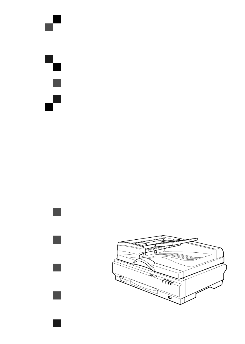
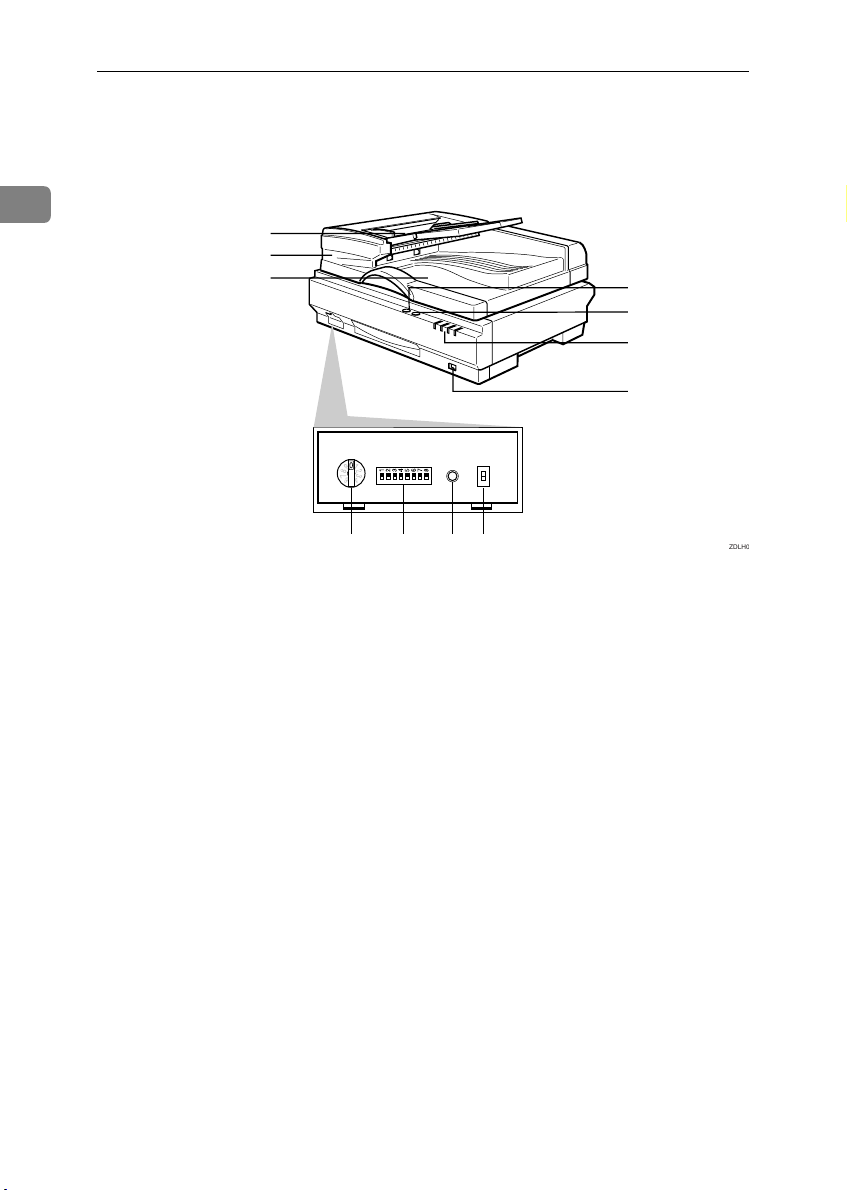
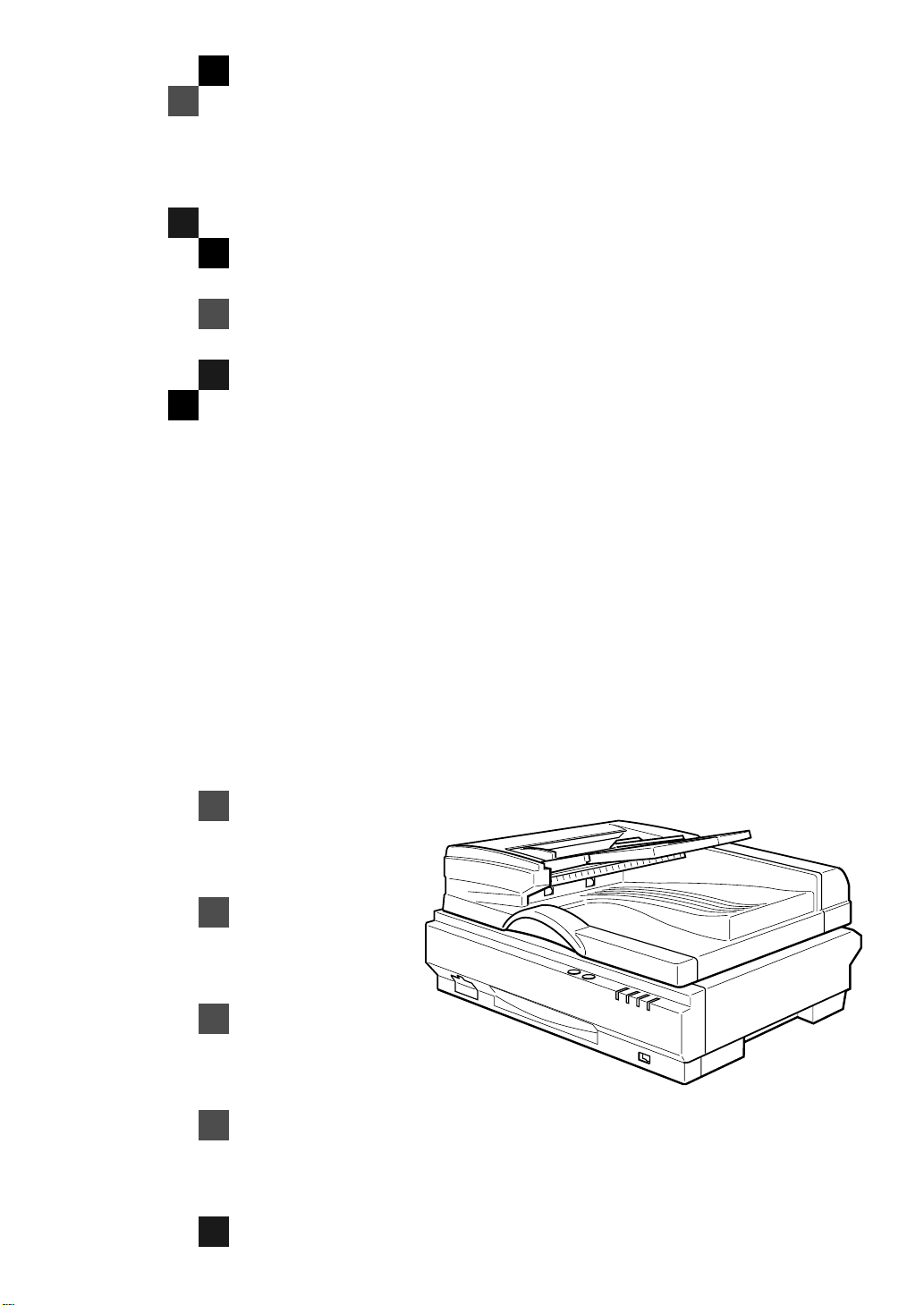
Guide to This Scanner
1
1
2
3
4
5
6
7
8 9 10 11
1.
Document Tray
Set the document to be scanned by the
Automatic Document Feeder (ADF).
2.
Automatic Document Feeder
(ADF)
Use to automatically feed and scan documents.
3.
Output Tray
Documents scanned using the Automatic
Document Feeder (ADF) are discharged
here.
4.
{{{{Reset}}}} key
Used when manual scanning is completed.
5.
{{{{Start}}}} key
Used when starting manual scanning.
6.
Indicators
For confirming the status of the unit.
7.
Power Switch
For switching on and off the power to
this unit.
ZDLH
8.
Rotary Switch
Used for setting the SCSI ID.
9.
DIP Switches
These switches are for setting the operation mode.
10.
Hard Reset Switch
This switch resets the power to this unit.
Use to validate the settings of the DIP
Switches and Rotary Switch.
11.
SCSI/IEEE1394 Selection Switch
Use to switch between the SCSI interface
and the IEEE1394 Interface (optional) .
4
Page 17
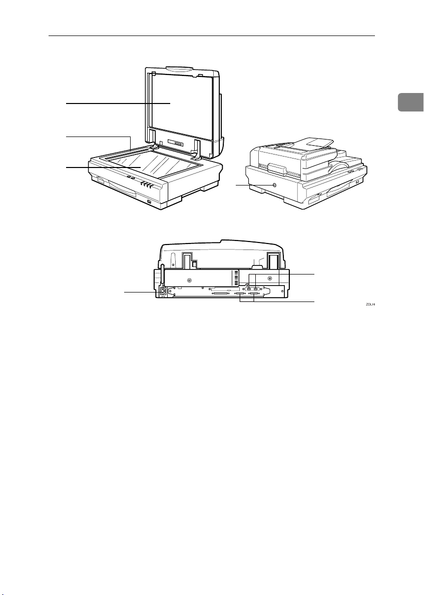
Guide to This Scanner
0
1
2
3
5
1.
White Sheet
This holds documents against the Contact Glass.
2.
ADF Contact Glass
Place the documents set at the Automatic
Document Feeder (ADF) to be scanned
here.
3.
Contact Glass
Place the documents to be scanned here.
4.
Lock Switch
Use to lock the internal scanning equipment when transporting the scanner.
5.
Power Connector
Where the Power Cord is connected
6.
IEEE1394 Connector (optional)
Where the IEEE1394 cable is connected
7.
SCSI connector
Where the SCSI cable is connected
1
4
6
7
ZDLH
5
Page 18
Getting Started
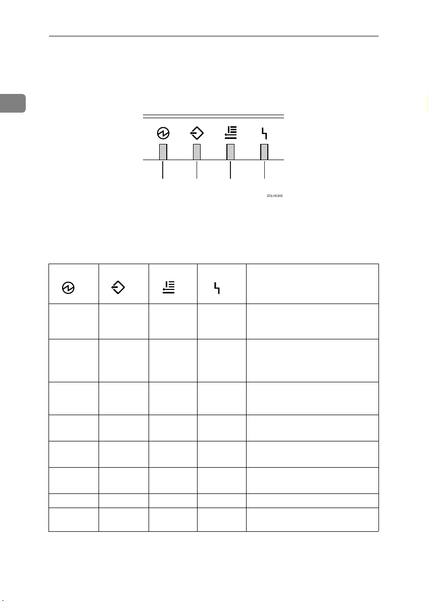
Understanding the Indicators
This unit is equipped with the following indicators.
1
1 2 3 4
ZDLH030E
1.
Power On
2.
Machine Busy
3.
Document in Place
4.
Error
Under normal circumstances, the indicators of this unit are as follows. Under
other circumstances, an error reading will occur. Refer to resolve the error.
Description
When switching on the power or
✩✩✩✩
✩
✩
✩✩
✩✩✩
✩
★
★
---
-
-
- - - During the Low Power mode
-
✩
--
★
★
when performing a hard reset
(for only a few seconds)
When the Automatic Document
Feeder (ADF) contains no documents and scanning is not taking
place
When the Automatic Document
-
Feeder (ADF) contains a document
but scanning is not taking place.
During the transmission of scanned data
(No Documents in the ADF)
During the transmission of scanned data.
(Documents in the ADF)
During standby for manual scan.
(Before pressing the
When manual scan is in the standby
mode during the Low Power mode.
{Start}
key)
6
✩:On
★:Flashing
-:Off
Page 19
Confirmations Prior to Installation
R
R
Confirmations Prior to Installation
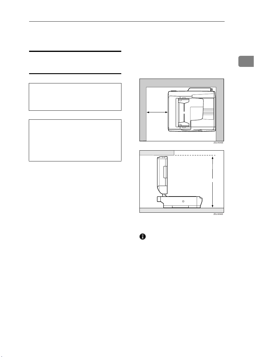
❖❖❖❖ Installation space
Confirming the Installation
Environment
WARNING:
• Confirm that the wall outlet is near the
machine and freely accessible, so that in
event of an emergency, it can be unplugged easily.
Install on a location that guarantees a space as shown in the illustration.
1
CAUTION:
• Keep the machine away from humidity
and dust. A fire or an electric shock might
occur.
• Place the machine on a strong and level
surface. Otherwise, th e machine might fall
and cause personal injury.
Select a horizontal, stable location
free from vibrations to install the unit.
• The Degree of levelness of the surface to install the unit on: left to
right and back to front, 5mm (0.2”)
or less.
100mm or more
(3.9")
660mm or more
(26.0")
❖❖❖❖ Installation environment
Important
❒ Do not install on the following
locations:
• On locations exposed to direct sun light
• On places exposed to direct
radiation or hot air from an
air-conditioner or heater
• Near electronic equipment
such as a radio, a TV, etc.
• Exceedingly hot, humid, cold
locations
• Near a humidifier
ZDLH040E
ZDLH050E
7
Page 20
Getting Started
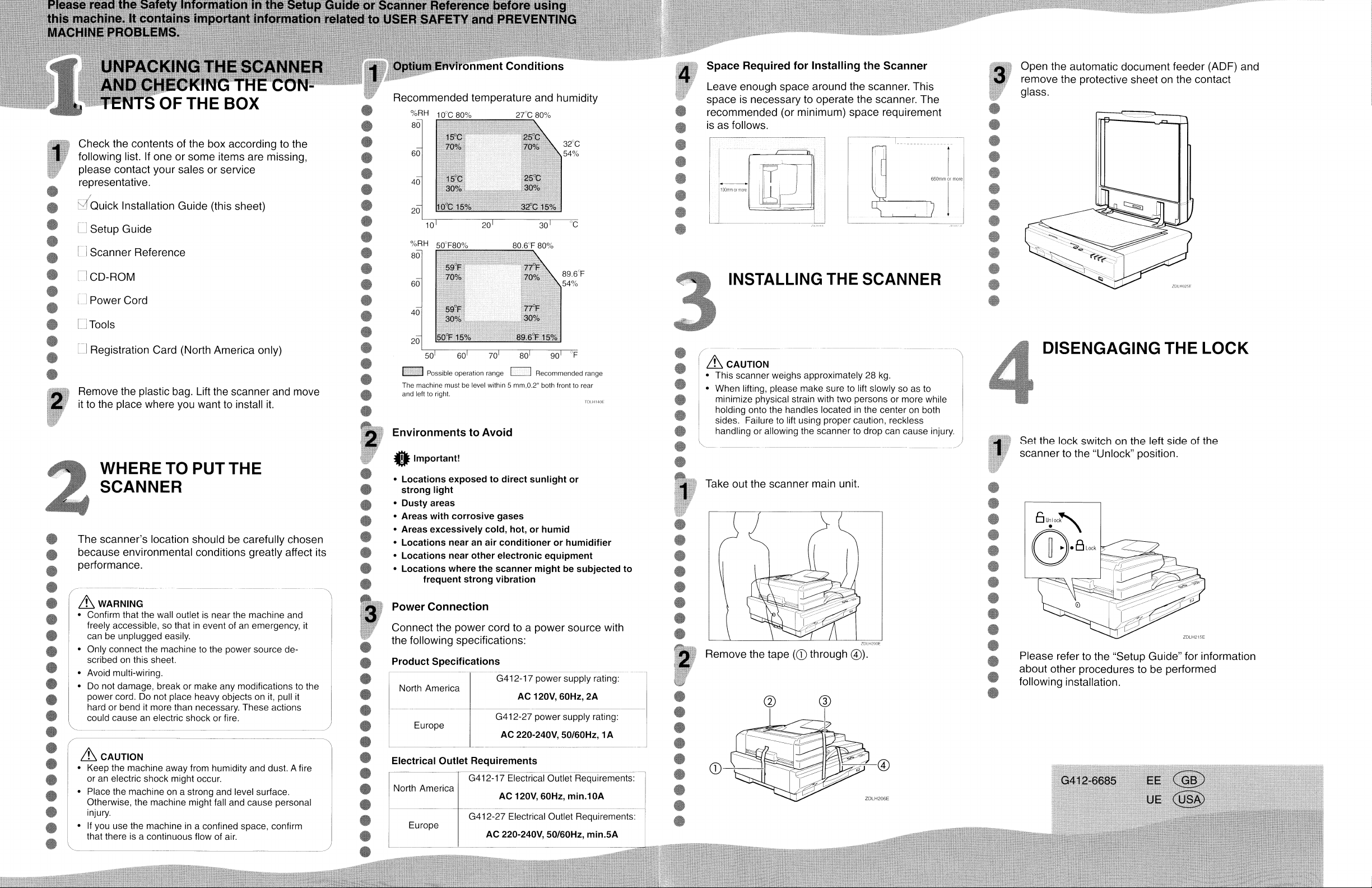
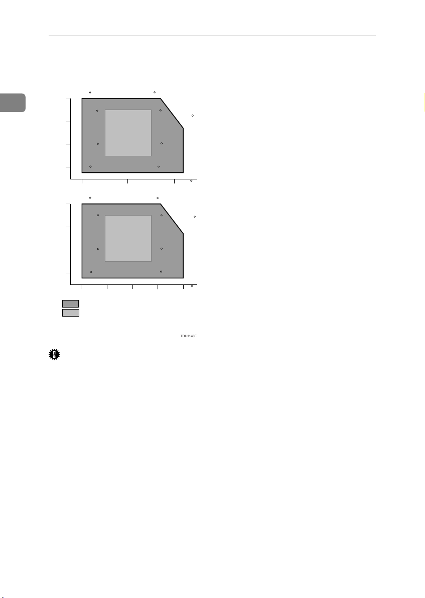
❖❖❖❖ Optimum Environmental Conditions
Recommended temperature and
humidity
%RH
1
80
15 C
70%
60
27 C 80%10 C 80%
25 C
70%
32 C
54%
15 C
40
30%
10 C 15%
20
10 20 30
%RH
80
59 F
70%
60
59 F
40
30%
50 F 15%
20
50 70 8060 90
Possible operation range
Recommended range
The machine must be level within 5 mm, 0.2"
both front to rear and left to right.
25 C
30%
32 C 15%
80.6 F 80%50 F80%
77 F
70%
77 F
30%
89.6 F 15%
89.6 F
54%
TDLH140E
C
F
Important
❒ To be able to transport this unit,
keep its packaging material and
box handy.
❒ When moving the unit from a cold
to a warm location, condensation
can occur internally. In case condensation has occurred, allow the
unit to acclimatize to the new environment for at least one hour.
8
Page 21
Connecting the Power Cord
R
R
Connecting the Power Cord
The following explains the order for
connecting the Power Cord to this
unit.
WARNING:
• Do not use with a power source with a
voltage different from the specified voltage. Do not use a power outlet with multiple devices plugged in. These could create
the risk of fire or electric shock.
• Avoid the use of an extension cord.
• Do not damage, break, twist or modify the
Power Cord. Placing heavy objects on the
cord, pulling on or bending it excessively
can damage the Power Cord, creating the
risk of fire or electric shock.
• Never touch or unplug the power plug
with wet hands. This can create the risk of
electric shock.
CAUTION:
• When unplugging from an outlet, be sure
to grasp the plug when pulling. Never
pull on the cord. This could damage the
cord creating the risk of fire or electrical
shock.
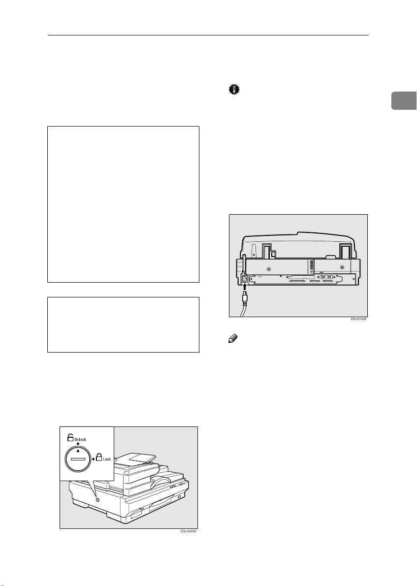
Make sure that the Power Switch
A
is set to the OFF position.
Make sure that the locking switch
B
on the left side panel of the main
unit is set to the {{{{Unlock}}}} position.
Important
❒ Always make sure that the lock-
ing switch is in the {Unlock} position. Switching on the power
while this switch is not released,
the unit will not be able to perform scans and defects can occur.
Fully insert the Power Cord into
C
the Power Connector on the main
unit.
Note
❒ For the Power Cord, use the ca-
ble that comes with this unit.
Insert the power plug into the
D
power outlet.
1
ZDLH100E
ZDLH220E
9
Page 22
Getting Started
Connecting to the PC
This unit has an interface that com-
1
plies with SCSI-2/3 standards and an
interface that complies with IEEE1394
standards (option). This explanation
describes the connection methods for
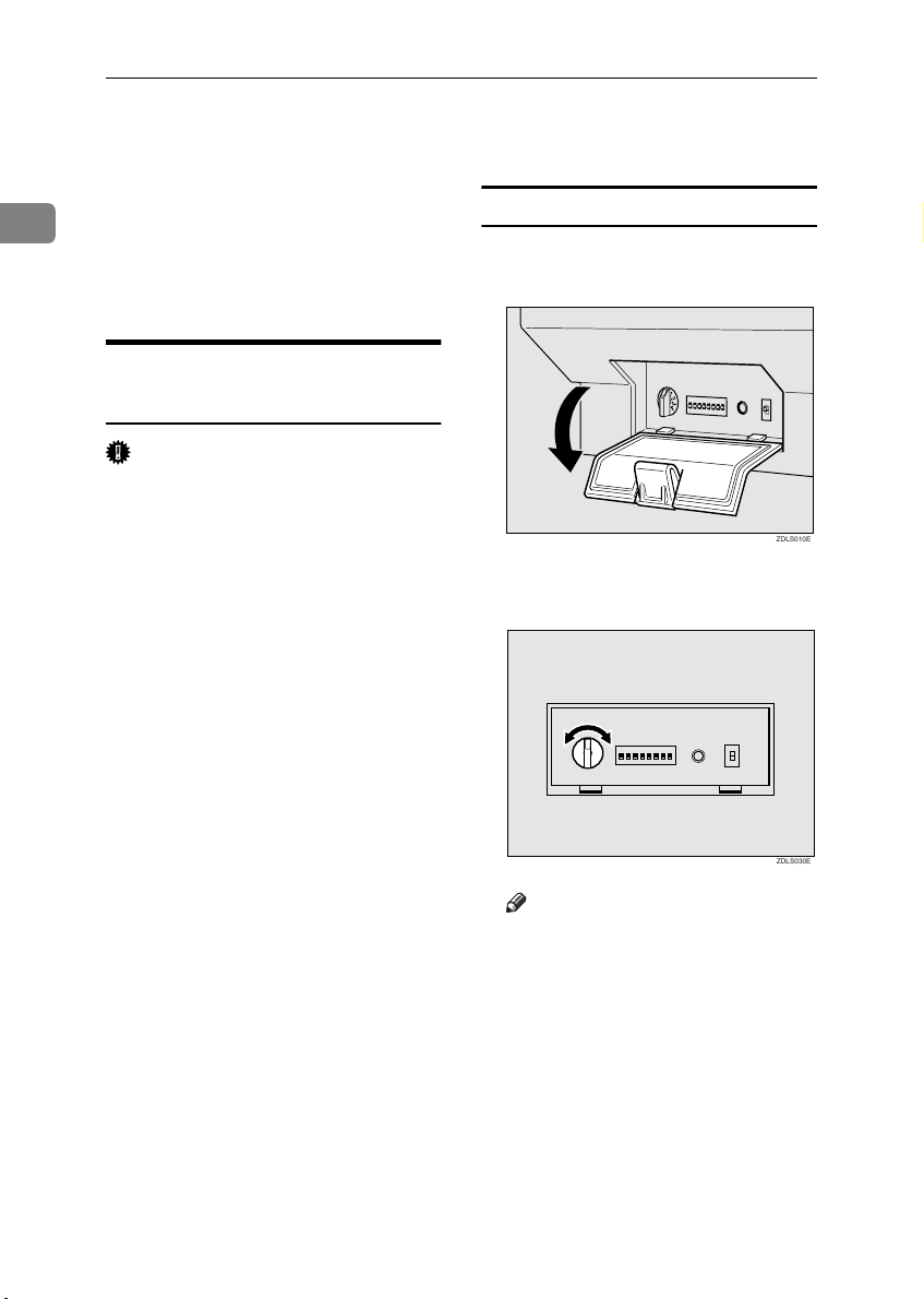
Setting the SCSI ID
Open the cover at the lower left of
A
the main unit.
both types of interface.
Connecting to the SCSI
Interface
Important
❒ When connecting this unit to other
SCSI devices through a daisychain,
possibly it doesn't work properly.
❒ The SCSI interface of this unit is of
the 50-pin half-pitch (pin-type)
type. Connect a shielded SCSI-2
compliant with ANSI standards or
a SCSI-3 (Ultra-SCSI) cable. When
other cables are used, there is the
possibility of malfunction or radio
interference due to exceeding the
maximum value of the FCC rules.
❒ It is possible that malfunction oc-
curs or data is lost when more than
one SCSI ID's exists simultaneously. Adjust the settings such that the
SCSI ID of this unit does not coincide with the ID of another SCSI
device.
❒ Keep the total length of the SCSI
cable including the cable inside the
PC to a maximum of 1.5m (4.9 feet)
when using the SCSI-3 (Ultra-SCSI) and 3m (9.8 feet) when using
the SCSI-2.
❒ This unit may not work properly
in combination with other SCSI
boards or cables. If this is the case,
connect only this unit to the PC.
Set the SCSI ID by rotating the
B
Rotary Switch.
1
0
2
9
1234567
3
8
4
7
5
6
8
Note
❒ Press the Hard Reset Switch
when changing the setting
while the power is switched on.
ZDLS010E
ZDLS030E
10
Page 23
Connecting to the PC
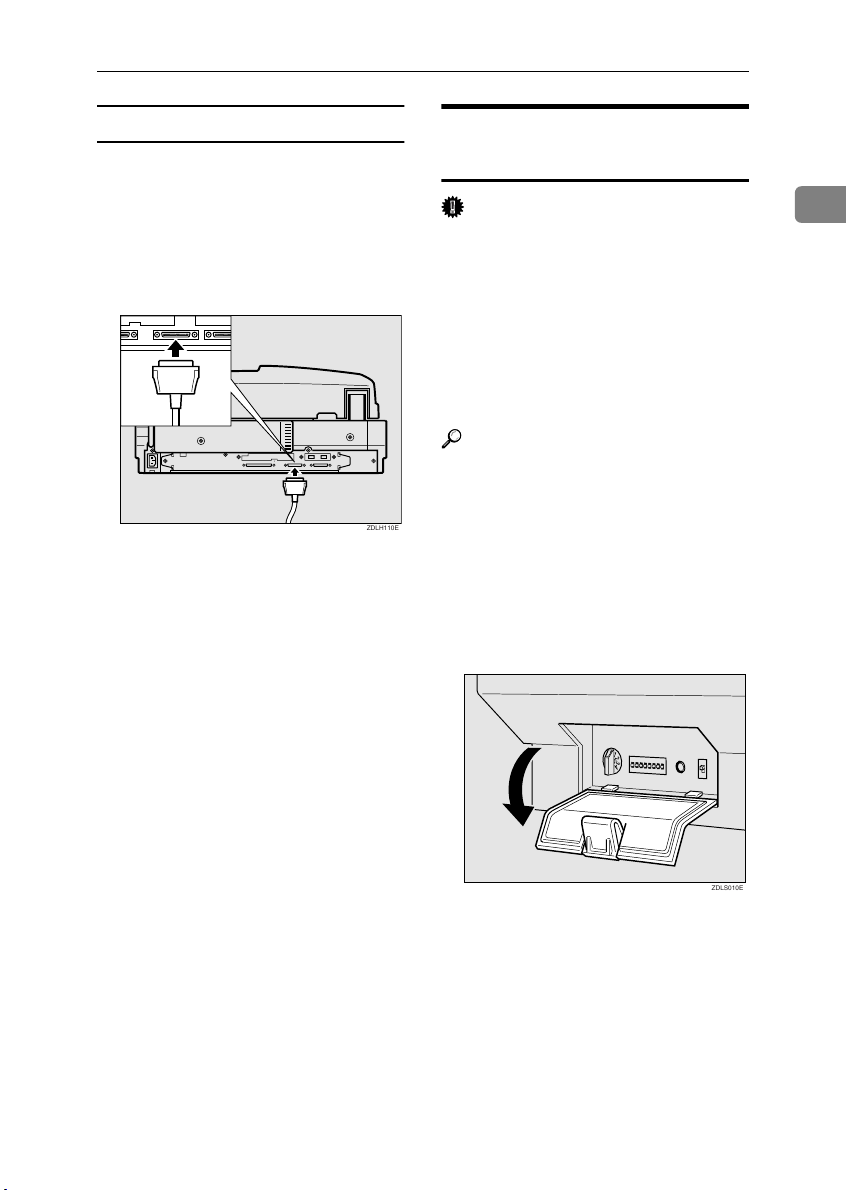
Connecting a SCSI cable
Switch off the power to the PC
A
and all devices connected
through the SCSI interface.
Connect the SCSI Connector of
B
this unit to the SCSI board of the
PC using the SCSI cable.
Open the cover at the lower left of
C
the main unit and check the setting of the 3rd DIP switch.
• If this unit is the last unit of the
daisychain, set the 3rd DIP
switch to OFF.
• If this unit is not the last unit of
the daisychain, set the 3rd DIP
switch to ON.
ZDLH110E
Connecting to the IEEE1394
Interface (optional)
Important
❒ Use the cable that comes with the
IEEE1394 Board when using this
unit.
❒
When connecting multiple IEEE1394
compatible devices to multiple PC's,
the operation may become unstable.
Please make sure proper operation
when connecting multiple IEEE1394
compatible devices.
Reference
An IEEE1394 Interface can be used
by installing an optional IEEE1394
Board on this unit. For information
about how to install an IEEE1394
Board, refer to P.13 “Installing the
IEEE 1394 Board (IEEE 1394 Interface Board Type S)”.
Open the cover at the lower left of
A
the main unit.
1
Switch on the power to this unit
D
and the power of the PC.
For the installation of the necessary software when using this unit,
refer to P.17 “Installing the Scanner
drivers”.
ZDLS010E
11
Page 24
Getting Started
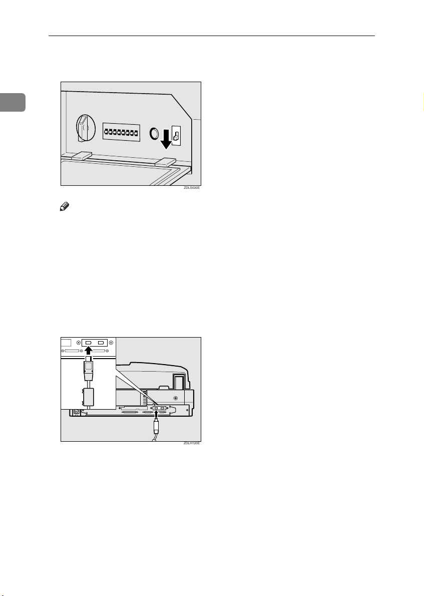
Set the SCSI/IEEE1394 Selector
B
Switch to [1394].
1
1
0
2
9
3
8
4
7
5
6
ZDLS020E
Note
❒ When changing settings while
the power is switched on, be
sure to perform a hard reset by
pressing the Hard Reset Switch.
Use a cable to connect the IEEE1394
C
connector of this unit to the
IEEE1394 connector of the PC
Connect the side of the cable that
has a core to the IEEE1394 connector of this unit.
.
12
ZDLH120E
Page 25
Installing Options
Installing the IEEE 1394 Board
(IEEE 1394 Interface Board Type S)
Important
❒ Before touching the IEEE 1394
Board, make sure to first touch a
metal object to discharge any static
electricity accumulated in your
body.
Installing Options
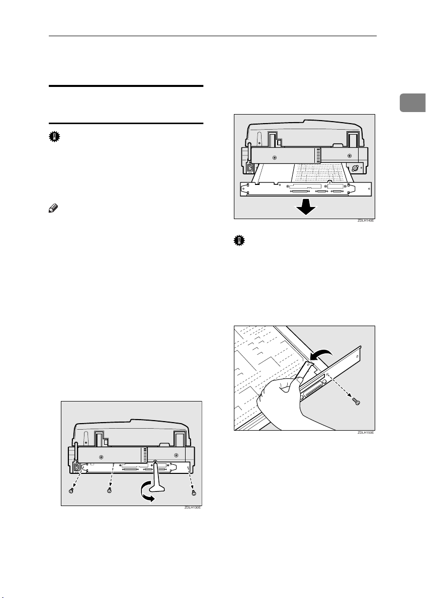
Pull and slide the scanner control
D
unit out.
1
Note
❒ Please use only the tools provided
for removing and tightening
screws.
Check the contents of the box for
A
the following items:
• IEEE 1394 Interface Board Type
S
• Tools
Turn off the power of the scanner
B
and unplug the Power Cord and
all other cables that are connected
to it.
Remove the four screws at the
C
bottom of the back panel.
Important
❒ The control unit is very heavy.
Be careful not to drop it when
removing.
Remove the screw, and then re-
E
move the cover of the scanner
control unit.
ZDLH140E
ZDLH150E
ZDLH130E
13
Page 26
Getting Started
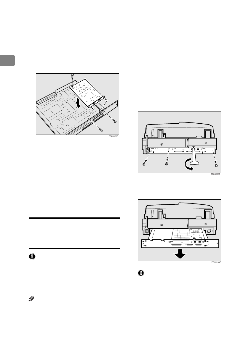
Attach the IEEE 1394 Board to the
F
scanner control unit, and then fasten in place with the screws removed in step
1
included with the IEEE 1394
Board.
Be sure to attach firmly, and con-
G
firm that there are no metal objects or other foreign objects on
the scanner control unit.
Insert the scanner control unit
H
into the scanner, and then fasten
in place with the four screws.
Connect the cables to the scanner,
I
and then connect the Power Cord.
and the screws
E
ZDLH160E
Check the contents of the box for
A
the following items:
• Image Processing Unit Type A
• Tools
Turn off the power of the scanner
B
and unplug the Power Cord and
all other cables that are connected
to it.
Remove the four screws at the
C
bottom of the back panel.
Pull and slide the scanner control
D
unit out.
ZDLH230E
Installation of Image Processing
Unit
(Image Processing Unit Type A)
Important
❒ Before touching the image process-
ing unit, make sure to first touch a
metal object to discharge any static
electricity accumulated in your
body.
Note
❒ Please use only the tools provided
for removing and tightening
screws.
14
ZDLH230E
Important
❒ The control unit is very heavy.
Be careful not to drop it when
removing.
Page 27
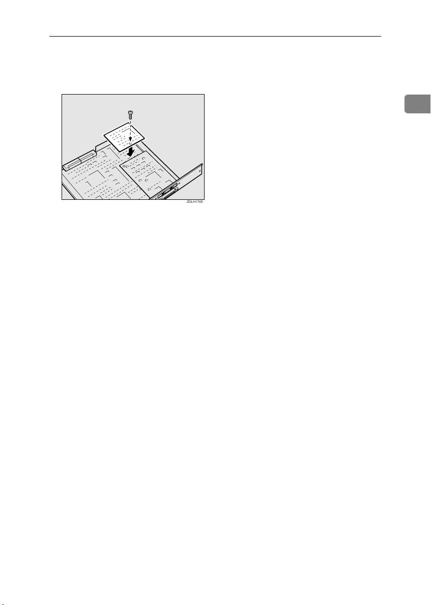
Attach the image processing unit
E
to the scanner control unit and
fasten with the enclosed screw.
After confirming that the image
F
processing unit is securely attached, check to make sure that
there are no metal or other foreign
objects on the scanner control
unit.
Insert the scanner control unit
G
into the scanner and fasten in
place with the four screws.
Installing Options
1
ZDLH170E
Connect the cables to the scanner,
H
and then connect the Power Cord.
15
Page 28

Getting Started
1
16
Page 29

2. Installing the Scanner
drivers
This chapter assumes that the reader has sufficient understanding of the Windows operating system. Refer to the Windows operation manual for details
about its functions and operation.
The ways for installing the scanner driver on your computer vary depending on
your operating system. Follow the procedures described below (The following
is an explanation on how the TWAIN driver is installed. When installing the ISIS
Driver, refer to P.18 “Installing the Scanner Driver by Auto Run” and proceed with
the installation as mentioned there.).
Note
❒ The scanner driver in this manual is TWAIN or ISIS driver.
Using Windows98/ME, Windows2000
Install the Scanner driver after having installed the STI driver for Windows98/
Me or Windows2000 using the Plug & Play function of the OS. Here examples of
Windows98 are used for the explanations. The basic operations are similar for
Windows Me and Windows2000.
Installing the STI Driver
When connecting the scanner to a PC and the PC is started, the scanner can possibly be recognized as a different device. In order to allow the scanner to be recognized properly, it is necessary to install the STI driver stored on the supplied
CD-ROM. When using this product with Windows98/Me or Windows2000 be
sure to always install the STI driver.
Limitation
❒ To install the driver when using Windows2000, log-on as an Administrator
group member.
Note
❒ During the installation of the STI driver, the Windows98/Me or
Windows2000 CD-ROM may be required.
Connect the scanner and start up the PC.
A
When starting up the PC for the first time after connecting the scanner, the
[Add New Hardware Wizard] appears.
17
Page 30

Installing the Scanner drivers
Note
❒ If the [Add New Hardware Wizard] does not appear after starting up the PC,
click the [Device Manager] tab on [System] in the [Control Panel], select the
scanner name and click [Remove]. The [Confirm Device Removal] dialog box
will be displayed, click [OK] and restart the system. The scanner is now recognized as a [Unknown Device] and [Add New Hardware Wizard] appears.
Click [Search for the best driver for your device. (recommended)] and click [Next].
2
B
Select the [Specify a location] check box, input [ \DRIVERS\SC-
C
SI\STI\INF2000 ] after the CD-ROM drive name (in the case of
Windows98/Me) and input [ \DRIVERS\SCSI\STI\INF2000 ] after the
CD-ROM drive name (in the case of Windows2000).
For example, when the D drive is the CD-ROM drive, input [ C:\DRIVERS\SCSI\STI\INF98 ] or [ C:\DRIVERS\SCSI\STI\INF2000 ] respectively.
Click [Next].
D
Click [Next].
E
The [Insert disk] message appears.
Place the CD-ROM included with this product into the CD-ROM drive and
F
click [OK].
Click [Finish].
G
Open [System] in the [Control Panel] and check that the scanner is correctly
H
identified by the [Device Manager].
Installing the Scanner Driver by Auto Run
You can install the scanner drivers and software, and set them up easily by using
Auto Run.
Follow these steps to install the scanner drivers and software on Windows 95/
98/Me, Windows 2000 or Windows NT 4.0.
Limitation
❒ If your system is Windows 2000 or Windows NT 4.0, installing a scanner driv-
er by Auto Run requires Administrators permission. When you install a scanner driver by Auto Run, log on using an account that has Administrators
permission.
Note
❒ Auto Run might not automatically work with certain OS settings. In this case,
launch " CDLAUNCH.EXE " located on the CD-ROM root directory.
18
Page 31

Using Windows98/ME, Windows2000
❒ If you want to cancel Auto Run, hold down the { SHIFT} key (when your sys-
tem is Windows 2000, hold down the left {SHIFT} key) while inserting the CDROM. Keep the {SHIFT} key held down until the computer has finished accessing the CD-ROM.
Close all applications that are running.
A
Insert the CD-ROM into the CD-ROM drive.
B
Follow the instructions on the screen.
C
Restart the computer after installation is complete.
D
Set up the options with the scanner driver.
E
2
19
Page 32

Installing the Scanner drivers
Using Windows95, WindowsNT4.0
To install the scanner driver for Windows 95, WindowsNT4.0, refer to
P.18 “Installing the Scanner Driver by
Auto Run”.
2
Limitation
❒ To install the driver when using
WindowsNT4.0, log-on as a member of the Administrator group.
20
Page 33

Using WindowsNT3.51
To install the scanner driver for
WindowsNT3.51, follow the steps described below.
Limitation
❒ To install the driver when using
WindowsNT3.51, log-on as a
member of the Administrator
group.
❒ The ISIS Driver does not work
with Windows NT3.51.
Installing the TWAIN driver
Place the CD-ROM included with
A
this product into the CD-ROM
drive.
Select [Run] from the [File] menu
B
in the [File Manager].
The [Run] dialog box appears.
Using WindowsNT3.51
2
Inside the
C
DRIVERS\SCSI\TWAIN\OTHERS\SETUP ] after the name of the
drive in which the CD-ROM is located and click
For example, if the CD-ROM is
placed in the D drive, input [D:
\DRIVERS\SCSI\TWAIN\OTHERS\SETUP ]
Follow the instructions on the
D
screen.
Restart the computer after instal-
E
lation is complete.
[Command Line]
[Finish]
box, input [
.
21
Page 34

Installing the Scanner drivers
About the Software on the CD-ROM
List of Files
The CD-ROM includes the software below.
2
CDROM
DRIVE
DRIVERS SCSI TW
AIN
STI INF9
ISIS
UTILITY
nese
ers
8
000
TWAIN Driver
TWAIN driver is the driver used to enable this unit to scan documents. Make
sure this driver is installed.
By selecting a device of a commercially available TWAIN compatible driver,
when designating this driver, it will automatically start up when scanning documents and it will scan according to designated scanning conditions.
If the multiple scanning mode is stored beforehand, it can be recalled when scanning.
TWAIN driver for Windows95/98/Me,
Japa-
Windows2000, WindowsNT3.51/4.0
TWAIN driver for Windows95/98/Me,
Oth-
Windows2000, WindowsNT3.51/4.0
STI driver for Windows98/Me
STI driver for Windows2000
INF2
ISIS driver for Windows95/98/Me,
Windows2000, WindowsNT4.0
❖❖❖❖ Files storing location
Files are stored in the following location in the provided CD-ROM.
\DRIVERS\SCSI\TWAIN\Others\
❖❖❖❖ Operating environment
• PC
The driver is compatible with the following operating systems:
PC/AT compatible machines
Limitation
❒ When used with WindowsNT, the driver will not operate in a RISC-
based (MIPS R-series, Alpha AXP, Power PC) environment.
• Compatible Operating Systems
Microsoft Windows 95
Microsoft Windows 98, 98SE
Windows Millenium Edition
22
Page 35

About the Software on the CD-ROM
Windows 2000 Professional
Windows 2000 Server
Windows NT WorkStation 4.0 Service Pack 5.0 or higher
Windows NT Server 4.0 Service Pack 5.0 or higher
Windows NT 3.51 Service Pack 5.0 or higher
• Display resolution
SVGA 800x600
• TWAIN compatible applications
Applications compatible with TWAIN version 1.6 or higher
ISIS Driver
The ISIS Driver is necessary for scanning documents with the scanner. It is possible to scan documents, when calling up the ISIS Driver with applications that
are compatible with ISIS. It is also possible to use the driver when connecting a
computer and the machine through a SCSI interface.
❖❖❖❖ Files storing location
Files are stored in the following location in the provided CD-ROM.
\DRIVERS\SCSI\ISIS\
❖❖❖❖ Operating environment
• PC
The driver is compatible with the following operating systems:
PC/AT compatible machines
2
Limitation
❒ When used with WindowsNT, the driver will not operate in a RISC-
based (MIPS R-series, Alpha AXP, Power PC) environment.
• Compatible Operating Systems
Microsoft Windows 95
Microsoft Windows 98, 98SE
Windows Millenium Edition
Windows 2000 Professional
Windows 2000 Server
Windows NT WorkStation 4.0 Service Pack 5.0 or higher
Windows NT Server 4.0 Service Pack 5.0 or higher
Limitation
❒ The ISIS Driver does not work with Windows NT3.51.
• Display resolution
SVGA 800x600
23
Page 36

INDEX
A
About the Software on the CD-ROM, 22
ADF Contact Glass
Automatic Document Feeder (ADF)
Auto Run
, 18
,
5
, 4
C
Caution
Confirming the Installation Environment
7
Connection
Contact Glass
ii
,
IEEE1394 Interface
Power Cord
SCSI Interface
,
,
5
9
, 10
, 11
D
DIP Switches, 4
Document Tray
, 4
G
Guide to This Scanner, 4
H
Hard Reset Switch, 4
I
Power Switch
, 4
Q
Quick Installation Guide, v
R
{Reset} key
Rotary Switch
,
S
Scanner Reference, v
SCSI Connector
SCSI/IEEE1394 Selection Switch
Setup Guide
{Start}
, 4
, 4
,
, 4
T
TWAIN Driver, 22
U
Understanding the indicators, 6
W
Warning, ii
White Sheet
,
5
, 5
, 4
v
IEEE1394 Connector (optional)
Indicators
Installing Options
Installing the STI driver
ISIS Driver
, 4
Image Processing Unit
IEEE1394 Board
, 23
L
Lock Switch, 5
O
Output Tray, 4
P
Power Connector, 5
24
,
13
,
13
, 17
, 14
,
5
Page 37

Color Scanner Setup Guide
Printed in the Japan
UE USA G412-6653
Page 38

Color Scanner Setup Guide
Printed in the Japan
UE USA G412-6653
Page 39
Color Scanner
Operating Instructions
Scanner Reference
ZDLH001E.eps
Read this manual carefully before you use this product and keep it handy for future
reference.
For safety, please follow the instructions in this manual.
Page 40

Introduction
This manual contains detailed instructions on the operation and maintenance of this machine. To get
maximum versatil ity from this machi ne all operator s shoul d carefully read and follow the i nstruc tions in
this manual. Please keep this manual in a handy place near the machine.
Please read the Safety Information before using this machine. It contains important information related
to USER SAFETY and PREVENTING EQUIPMENT PROBLEMS.
Power Source
Color Scanner: 120 V, 60 Hz, 10A or more
Please be sure to connect the Powe r Cord to a pow er sou rce as above.
Two kinds of size notation are employed in this manual. With this machine refer to the inch version.
Important
Parts of this manual are subject to change without prior notice. In no event will the company be liable
for direct, indirect, special, incidental, or consequential damages as a result of handling or operating
the machine.
Caution:
Use of controls or adjustment or performance of procedures other than those specified in this manual
might result in hazard ous radiation exposure.
Do not attempt any maintenance or troubleshooting other than that mentioned in this manual. This
scanner contains a laser beam generator and direct exposure to laser beams can cause permanent
eye damage.
Two kinds of size notation are employed in this manual. With this machine refer to the inch version.
Ricoh shall not be respons ible fo r any da mage or e xpens e that m ight res ult from the use o f parts ot her
than genuine Ricoh parts in your Ricoh office product.
Page 41

Trademarks
Microsoft®, Windows® and Windows NT® are registered trademarks of Microsoft Corporation in the United States and/or other countries.
Other product names used herein are for identification purposes only and might
be trademarks of their respective companies. We disclaim any and all rights in
those marks.
Notes:
Some illustrations might be slightly different from your machine.
Certain options might not be available in some countries. For details, please contact your local dealer.
Note
The proper names of the Windows operating systems are as follows:
•Microsoft
•Microsoft
•Microsoft
•Microsoft
•Microsoft
•Microsoft
•Microsoft
•Microsoft
•Microsoft
®
Windows® 95 operating system
®
Windows® 98 operating system
®
Windows® Millennium Edition (Windows Me) operating system
®
Windows® 2000 Professional
®
Windows® 2000 Server
®
Windows NT® Server operating system Version 4.0
®
Windows NT® Workstation operating system Version 4.0
®
Windows NT® Server network operating system version 3.51
®
Windows NT® Workstation operating system version 3.51
i
Page 42

Safety Information
R
R
When using your scanner, the following safety precautions should always be
followed.
Safety During Operation
In this manual, the following important symbols are used:
WARNING:
Indicates a potentially hazardous situation which, if instructions
are not followed, could result in death or serious injury.
CAUTION:
Indicates a p o tentially hazardou s situation which, if i nst r uctions are
not followed, may result in minor or moderate injury or damage to
property.
R WARNING:
• Connect the Power Cord directly into a wall outlet and never use an extension cord.
• Disconnect the power plug (by pulling the plug, not the cable) if the power cable or plug
becomes frayed or otherwise damaged.
• To avoid hazardous electric shock or laser radiation exposure, do not remove any covers
or screws other than those specified in this manual.
• Turn off the power and disconnect the power plug (by pulling the plug, not the cable) if
any of the following conditions exists:
• You spill something into the equipment.
• You suspect that your equipment needs service or repair.
• Your equipment's cover has been damaged.
• Disposal can take place at our authorized dealer or at appropriate collection sites.
ii
Page 43

R CAUTION:
• Protect the equipment from dampness or wet weather, such as rain, snow, and so on.
• Unplug the Power Cord from the wall outlet before you move the equipment.
While moving the equipment, you should take care that the Power Cord will not be damaged under the equipment.
• When you disconnect the power plug from the wall outlet, always pull the plug (not the
cable).
• Do not allow paper clips, staples, or other small metallic objects to fall inside the equipment.
• For environmental reasons, do not dispose of the equipment or expended supply waste
at household waste collection points. Disposal can take place at an authorized dealer or
at appropriate collection sites.
• The inside of the machine could be very hot. Do not touch the parts with a label indicating
the "hot surface". Otherwise it could cause a personal burn.
• Our products are engineered to meet high standards of quality and functionality, and we
recommend that you only use the expendable supplies available at an authorized dealer.
Lithium Batteries (Memory Back-up)
R WARNING:
• Do not try to replace the lithium batteries by yourself. A battery of this type can explode
if incorrectly replaced. If the lithium batteries need to be replaced, contact an authorized
dealer to request servicing.
• Never dispose of the lithium batteries by incineration. This can cause them to rupture resulting in injury.
Note
❒ Please return used NIC boards to our authorized dealer or service representative.
Your cooperation with our recycling activities is appreciated.
❒ NIC boards are equipped with a lithium battery. In the case NIC boards are disposed
of by the customer, please dispose them in accordance with national or local regulations after separating the lithium batteries from the NIC board.
iii
Page 44

Energy Star Program
As an ENERGY STAR Partner, we have determined
that this machine model meets the ENERGY STAR
Guidelines for energy efficiency.
The ENERGY STAR Guidelines intend to establish an international energy-saving system for
developing and introducing energy-efficient office equipment to deal with environmental issues, such as global warming.
When a product meets the ENERGY STAR Guidelines for energy efficiency, the Partner shall
place the ENERGY STAR logo onto the machine model.
This product was designed to reduce the environmental impact associated with office equipment by means of energy-saving features, such as Low-power mode.
❖❖❖❖ Energy Saver mode
This unit automatically lowers its power consumption at a predetermined
time (approximately 15 minutes) after the last operation was performed. To
operate the unit from this mode, see the instructions below.
• Method for clearing
• Put a document on the Document Tray.
• Open the cover of the Automatic Document Feeder (ADF).
• Open the White Sheet cover.
• Follow the instructions from the PC.
Note
❒ The Energy Saver mode does not work in the following conditions.
• When an optional device is attached.
• When an error occurs.
• When a document is placed on the Document Tray.
❖❖❖❖ Specifications
Energy Saver mode Power Consumption Approx. 11W
Default Time 15 minutes
iv
Page 45

Manuals for This Scanner
Manuals for This Scanner
The following manuals describe the operational and maintenance procedures of
this machine.
To enhance safe and efficient operation of this scanner, all users should read and
follow the instructions carefully.
❖❖❖❖ Quick Installation Guide
Describes how to install the scanner.
❖❖❖❖ Setup Guide
Provides information about setting up the scanner and its options. This manual is provided as a printed manual, and also as a PDF file on the CD-ROM.
❖❖❖❖ Scanner Reference(this manual)
Provides information about using the scanner. This manual is provided as a
PDF file.
❖❖❖❖ Network Interface Kit Installation Guide
Describes how to install the Network Interface Kit (Network Interface Board
Type S and Operation Unit).
Note
❒ There is a CD-ROM that comes with this scanner.
v
Page 46

How to Read This Manual
R
R
Symbols
In this manual, the following symbols are used:
WARNING:
This symbol indicates a potentially hazardous situation which, if instructions
are not followed, could result in death or serious injury.
CAUTION:
This symbol indicates a potentially hazardous situation which, if instructions
are not followed, may result in minor or moderate injury or damage to property.
* The statements above are notes for your safety.
Important
If this instruction is not followed, paper might be misfed, originals might be
damaged, or data might be lost. Be sure to read this.
Preparation
This symbol indicates the prior knowledge or preparations required before operating.
Note
This symbol indicates precautions for operation, or actions to take after misoperation.
Limitation
This symbol indicates numerical limits, functions that cannot be used together,
or conditions in which a particular function cannot be used.
Reference
This symbol indicates a reference.
[]
Keys that appear on the machine's panel display.
Keys and buttons that appear on the computer's display.
{}
Keys built into the machine's operation panel.
Keys on the computer's keyboard.
vi
Page 47

TABLE OF CONTENTS
1.Setting the Document
Size of Documents that can be Set.......................................................... 1
Document Sizes that can be Scanned Automatically .................................... 1
Documents that Require Special Care........................................... ............... 4
Placing the Document on the Contact Glass.......................................... 5
Setting Documents in the Automatic Document Feeder (ADF)............ 6
Simples Scanning ......................................................................................... 7
Duplex Scanning........................................................................................... 8
2.Scanning Documents
General Scanning Method................................. ................................. .... .. 9
Manual Scanning..................................................................................... 10
The Relationship between the Data Size and the Scanning Area, as well
as the Resolution........................... ..... ..... ................................ .............. 11
When in [Binary] [half-tone] is Selected...................................................... 11
When [gray-scale] is Selected..................................................................... 12
When [8 Colors] [8 Colors (half-tone) is Selected....................................... 13
When [256 colors] is Selected..................................................................... 14
When [16,770,000 colors] is selected......................................................... 15
3.Troubleshooting
When Scanning does not Start .............................................................. 17
When Scanning is not Performed as Expected.................................... 18
When the Indicators Show an Error Reading ....................................... 19
When a Document is Jamme d inside the Automatic Docume nt Feeder
(ADF)....................................................................................................... 20
Cleaning ................................................................................................... 21
Cleaning the Contact Glass, ADF Contact Glass, White Sheet, and White
Plate ......................................................................................................... 21
Cleaning the Feed Roller ............................................................................ 22
Cleaning the Document Roller ................................................................... 22
Cleaning the Document Rolling Unit .............................. ............................. 23
4.Appendix
Setting of the DIP Switches.................................................................... 25
Moving and Transporting the Scanner......................................... ......... 26
Moving Over Short Distances ..................................................................... 26
Transporting the Scanner............................................................................ 27
vii
Page 48

Discarding the Unit.......................... ........................................................ 28
Precautions Concerning the IEEE1394 Interface................................. 29
Specifications.......................................................................................... 30
Options..................................................................................................... 31
INDEX........................................................................................................ 32
viii
Page 49

1. Setting the Document
This chapter describes the methods used for setting documents on this unit for
scanning.
The document can be set on the Contact Glass or the Automatic Document Feeder (ADF). For scanning multiple documents in a row, the Automatic Document
Feeder (ADF) is convenient.
Size of Documents that can be Set
Position for
setting document
Contact Glass Maximum A3 , 11×17 (DLT) No restrictions
Automatic
Document
Feeder (ADF)
Size of document Document weight
❖❖❖❖ Standard size
Max. A3L, 11”×17”L
Min. A5L, 8.5”×5.5”(HLT)L
41(1.4oz)∼128g(4.5oz)/m
(35∼110Kg(77.2∼242.5lb))
2
❖❖❖❖ Non-standard size
Max:297mm(11.7”)×2000mm(78.8
”)(when scanning in binary),
297mm(11.7”) × 630mm(24.9”)
(when scanning in color)
Min: 105mm(4.1”) × 128mm(5.0”)
Document Sizes that can be Scanned Automatically
The sizes of documents that this unit can automatically detect and scan are as
follows.
❖❖❖❖ Contact Glass (Metric version)
Feed direction
A3 K 297 × 420
B4 K 257 × 364
A4 K 210 × 297
L 297 × 210
B5 K 182 × 257
L 257 × 182
Size (mm)
1
Page 50

Setting the Document
1
Feed direction
Foolscap
(F4, 8.5" × 13")
F/GL (8" × 13") K 203 × 330
K 216 × 330
❖❖❖❖ Contact Glass (Inch version)
Feed direction
Double Letter
(DLT)
11”× 15” K 11" × 15"
10”× 14” K 10" × 14"
K 11" × 17"
Size (mm)
Note
❒ F/GL size is detected same as the F4 size.
Size (inch)
Note
❒ This size is detected same as DLT size.
Legal (LG) K 8.5"× 14"
Letter (LT) K 8.5" × 11"
L 11" × 8.5"
8”× 10” K 8" × 10"
❖❖❖❖ Automatic Document Feeder (ADF)(Metric version)
Feed direction
A3 K 297 × 420
B4 K 257 × 364
A4 K 210 × 297
L 297 × 210
B5 K 182 × 257
L 257 × 182
2
Size (mm)
Page 51

Size of Documents that can be Set
Feed direction
A5 K 148 × 210
L 210 × 148
Foolscap (F4, 8.5" ×
13")
K 216 × 330
Size (mm)
Note
❒ Foolscap size is detected same as the F/GL
size.
F/GL (8" × 13") K 203 × 330
❖❖❖❖ Automatic Document Feeder (ADF)(Inch version)
Feed direction
Double Letter (DLT) K 11" × 17"
11”× 15” K 11" × 15"
Size (inch)
Note
❒ This size is detected same as the DLT size.
1
10”× 14” K 10" × 14"
Legal (LG) K 8.5"× 14"
F/GL K 8"× 13"
Note
❒ This size is detected same as the LG size.
Letter (LT) K 8.5" × 11"
L 11" × 8.5"
8”× 10” K 8" × 10"
Note
❒ This size is detected same as the LT size.
Half Letter(HLT) K 5.5" × 8.5"
L 8.5" × 5.5"
3
Page 52

1
Setting the Document
Documents that Require Special Care
Make sure to take care in setting the document according to the following instructions when scanning the following types of documents.
❖❖❖❖ Documents whose size is difficult to scan
As the following documents are difficult to scan their size, the correct size will
not be selected, even if the automatic size detection has been set. The sizes for
these documents should be manually set.
• Documents with projecting parts such as indices or attached lines
• Document with a high degree of transparency such as tracing paper or
OHP film
• Documents which are fully dark in color or which have a high content of
character or graphic patterns
• Documents with partially adhesive areas
• Documents with surrounding adhesive areas
❖❖❖❖ Documents that cannot be set into the Automatic Document Feeder (ADF)
The following types of documents should not be set into the Automatic Document Feeder (ADF) as these can cause paper jams, damage to the original
document, or black and white lines. If these types of documents are to be
used, use the Contact Glass of the scanner.
• Documents with staples or paper clips
• Documents with holes and rips
• Documents with bends, folds or wrinkles
• Pasted documents
• Thermal paper, art paper, aluminum foil, carbon paper, or processed pa-
per with conductive paper on the back
• Perforated paper
• Documents with projecting parts such as indices or attached lines
•
Documents that do not slide easily such as tracing paper (translucent paper)
• Documents that are thin and soft, such as registration paper
• Documents that have an unsuitable thickness such as postcards
• Documents that are bound such as books
• Documents that have a high transparency rate such as OHP film or tracing
paper
• Documents with not completely dried ink or correction liquid
4
Page 53

Placing the Document on the Contact Glass
Placing the Document on the Contact Glass
Important
❒
Take care that your fingers do not
get caught when closing the Automatic Document Feeder (ADF).
Open the Automatic Document
A
Feeder (ADF).
Place documents face down and
B
aligned with the scale.Documents
should conform to the setting
standards.
PS
1
Important
❒ Do not forcefully press down on
the Contact Glass. If a strong
force is applied to a small area,
the glass may be break.
Carefully close the Automatic
C
Document Feeder (ADF).
ZDLH180E
5
Page 54

Setting the Document
Setting Documents in the Automatic Document Feeder (ADF)
1
Multiple documents can be set in the
automatic document feeder(ADF). In
this manual, documents that can be
set in the Automatic Document Feeder (ADF) are called "sheet documents". Not only can documents set
in the Automatic Document Feeder
(ADF) be scanned on one side, they
can be scanned on both sides.
❖❖❖❖ Documents that cannot be set in the
Automatic Document Feeder (ADF)
• Documents that do not match
the size and paper weight of
documents that can be set
• Documents with staples, clips,
glue, etc.
• Documents with holes and rips
• Documents with bends, folds,
and wrinkles
• Pasted documents
• Wet documents
•
Documents that are bound, such
as books
•
Documents that are transparent
such as OHP film,or tracing paper
•
Documents that have curls such
as shown in the illustration below
5mm(0.2") or more
10mm(0.4") or more
• Documents not made of paper
•
Documents with coating (CFF,
etc.)
• Photos, documents that are
prints or printed photos
• Thermal fax paper, art paper,
aluminum foil, carbon paper,
processed paper with conductive paper on the back
•
Documents with projecting parts
such as indices or attached lines
• Documents that do not slide
easily such as tracing paper
(translucent paper)
• Documents that are thin and
soft, such as registration paper
• Documents that have an unsuitable thickness such as postal
6
cards
Important
❒ Setting documents that should
not be set in the Automatic Document Feeder (ADF) can cause
jams and break downs. Place
these documents on the Contact
Glass.
❖❖❖❖ Advice when Setting documents in
the Automatic Document Feeder
(ADF)
• Do not set more documents
than indicated.
• For document sizes that can be
automatically detected, refer to
P.1 “Document Sizes that can be
Scanned Automatically”.
Page 55

Setting Documents in the Automatic Document Feeder (ADF)
Simples Scanning
Set the documents into the Automatic Document Feeder (ADF) with the
A
side to be scanned face up.
ZDLY010E
Note
❒ Arrange the documents in the preferred order.
1
1
2
3
TACY050E
❒ To avoid multiple sheet feeds (in which the ADF feeds more than one sheet
at a time), fan the pages of the document before setting them in the Automatic Document Feeder (ADF).
❒ Set the document in the direction shown in the illustration to scan with the
proper orientation.
ZDLY020E
7
Page 56

1
Y
Setting the Document
Duplex Scanning
Set the documents in the Automatic Document Feeder (ADF) with the side
A
to be scanned first (the front side of the document) face up, and align the
document guide with the size of the documents.
ZDLY010E
Note
❒ Arrange the sheets of the documents in the order to be scanned.
1
2
3
4
6
5
TACY060E
❒ To avoid multiple sheet feeds (in which the ADF feeds more than one sheet
at a time), fan the pages of the document before setting them in the Automatic Document Feeder (ADF).
❒ When setting the front side of the page as in the illustration, the back side
is scanned upside.
ZDL
8
Page 57

2. Scanning Documents
General Scanning Method
Scanning of a document is initiated by the software that is TWAIN or ISIS compatible. The method of operation depends on the software. For details, refer to
the manual that was supplied with your software.
Limitation
❒ When using duplex scanning, if the leading edge of the reverse side of the
document is dark, the scanned image may appear whitish.
❒ When using the ISIS Driver, the image resolution will be limited. If the scan-
ning image is smaller than the size set with the ISIS Driver, lower the resolution (at maximum 675 dpi) using the resolution settings and the area.
9
Page 58

2
Scanning Documents
Manual Scanning
By setting up a scanner driver that supports the manual scanning function, scanning can be initiated by pressing the {Start} key.
If the manual scanning function is used, then communications between the scanner and the personal computer are no longer needed in cases where it is necessary to set the document in the scanner one sheet at a time, for example.
Set the manual scanning function through the scanner driver.
A
Set the documents in the scanner.
B
Press the {{{{Start}}}} key. To end manual scanning, press the {{{{Reset}}}} key.
C
10
Page 59

The Relationship between the Data Size and the Scanning Area, as well as the Resolution
The Relationship between the Data Size
and the Scanning Area, as well as the
Resolution
The resolution and the scanning area as well as the data size are all affected in
the following way.
• When the resolution (dpi) is set to a high value, the data size becomes larger
and the scanning area which can be set becomes smaller.
• When the scanning area is set larger, the data size becomes larger, and the resolution becomes lower.
Note
❒ The size of the scanning area is the standard.
❒ Scanning is not possible when there are blank fields in the setting.
❒ A data size that works with applications and a data size that can scan with a
scanner driver are different. For a data size that can work with applications,
refer to the manuals that came with each of the applications.
2
When in [Binary] [half-tone] is Selected
Paper
size
A3
A4
A5
A6
B4
B5
B6
× 17
11
LG
LT
5.5 × 8.5
Long
Width
(
mm / inch
297/11.7 420/16.5
210/8.3
148/5.8
105/4.1
257/10.1
182/7.2
128/5.0
279/11.0
216/8.5
216/8.5
140/5.5
297/11.7
Height
)
(
mm / inch
297/11.7
210/8.3
148/5.8
364/14.3
257/10.1
182/7.2
432/17.0
356/14.0
279/11.0
216/8.5
2000/78.7
100
)
1123 4491 17963 40416 161755
200
236 943 3772 8487 33968
118 470 1886 4247 16991 47181
58 234 940 2117 8468 23511
29 117 469 1058 4233 11755
176 705 2827 6365 25475
88 354 1415 3183 12734
43 175 703 1583 6339 17619
227 910 3647 8201 32826
145 580 2327 5231 20940
114 455 1823 4099 16412 45588
56 227 913 2058 8231 22870
Resolution(dpi)
400 600 1200 2000 2400
94398
70785
35393
91216
58170
135942
67969
33870
16935
101948
50972
25386
131353
83800
65676
32955
Numerical Value: Data Size (Unit = KB)
11
Page 60

Scanning Documents
When [gray-scale] is Selected
2
Paper
size
11
5.5 × 8.5
Long
Width
(
mm / inch
297/11.7 420/16.5
A3
A4
A5
148/5.8
105/4.1
A6
257/10.1
B4
182/7.2
B5
128/5.0
B6
279/11.0
× 17
216/8.5
LG
216/8.5
LT
140/5.5
297/11.7
)
210/8.3
Height
(
mm / inch
)
297/11.7
210/8.3
148/5.8
364/14.3
257/10.1
182/7.2
432/17.0
356/14.0
279/11.0
216/8.5
432/17.0
100
1887 7551 30209 67965
1415 5662 22654 50967 203883
1823 7294 29185 65668
1163 4653 18619 41897 167589
1941 7765 31072 69903
200
943 3774 15104 33979 135939
469 1881 7525 16934 67742 188166
235 940 3761 8467 33868 94077 135484
707 2831 11327 25483 101942
352 1409 5640 12691 50774 141033 203094
911 3646 14590 32834 131347
457 1829 7320 16477 65907 183074
Numerical Value: Data Size (Unit = KB)
Resolution(dpi)
400 600 1200 2000 2400
12
Page 61

The Relationship between the Data Size and the Scanning Area, as well as the Resolution
When [8 Colors] [8 Colors (half-tone) is Selected
Paper
size
11
5.5 × 8.5
Long
Width
(
mm / inch
297/11.7 420/16.5
A3
A4
A5
148/5.8
105/4.1
A6
257/10.1
B4
182/7.2
B5
128/5.0
B6
279/11.0
× 17
216/8.5
LG
LT
216/8.5
140/5.5
297/11.7
210/8.3
Height
)
(
mm / inch
297/11.7
210/8.3
148/5.8
364/14.3
257/10.1
182/7.2
432/17.0
356/14.0
279/11.0
216/8.5
432/17.0
100
)
200
943 3775 15101 33977 135929
471 1886 7550 16989 67963 188793
235 939 3762 8467 33871 94075 135484
117 470 1879 4233 16934 47033 67735
707 2830 11324 25483 101933
353 1415 5663 12739 50971 141593 203892
176 704 2818 6344 25383 70516 101547
911 3647 14589 32834 131343
581 2327 9307 20949 83794
456 1823 7293 16417 65673 182416
228 915 3660 8236 32954 91529
970 3883 15533 34947 139814
Numerical Value: Data Size (Unit = KB)
Resolution(dpi)
400 600 1200 2000 2400
2
131821
13
Page 62

Scanning Documents
When [256 colors] is Selected
2
Paper
size
11
5.5 × 8.5
Long
Width
(
mm / inch
297/11.7 420/16.5
A3
A4
A5
148/5.8
A6
105/4.1
B4
257/10.1
B5
182/7.2
128/5.0
B6
× 17
279/11.0
216/8.5
LG
LT
216/8.5
140/5.5
297/11.7
)
210/8.3
Height
(
mm / inch
)
297/11.7
210/8.3
148/5.8
364/14.3
257/10.1
182/7.2
432/17.0
356/14.0
279/11.0
216/8.5
432/17.0
100
1887 7551 30209 67965
1415 5662 22654 50967
1823 7294 29185 65668
1163 4653 18619 41897
1941 7765 31072 69903
200
943 3774 15104 33979
469 1881 7525 16934 67742
235 940 3761 8467 33868
707 2831 11327 25483
352 1409 5640 12691 50774
911 3646 14590 32834
457 1829 7320 16477
Numerical Value: Data Size (Unit = KB)
Resolution(dpi)
400 600 1200 2000 2400
65907
14
Page 63

The Relationship between the Data Size and the Scanning Area, as well as the Resolution
When [16,770,000 colors] is selected
Paper
size
11
5.5 × 8.5
Long
Width
(
mm / inch
297/11.7 420/16.5
A3
A4
A5
148/5.8
A6
105/4.1
B4
257/10.1
B5
182/7.2
128/5.0
B6
× 17
279/11.0
216/8.5
LG
LT
216/8.5
140/5.5
297/11.7
)
210/8.3
Height
(
mm / inch
)
297/11.7
210/8.3
148/5.8
364/14.3
257/10.1
182/7.2
432/17.0
356/14.0
279/11.0
216/8.5
432/17.0
100
5661 22652 90626 203894
2829 11322 45313 101937
1408 5642 22574 50801 203225
4244 16986 67961 152900
2121 8493 33981 76450
1055 4228 16919 38074 152321
5469 21881 87555 197005
3489 13960 55857 125692
2734 10937 43771 98502
1372 5488 21960 49431 197722
5822 23296 93216 209710
200
704 2819 11284 25401 101603
Numerical Value: Data Size (Unit = KB)
Resolution(dpi)
400 600 1200 2000 2400
2
15
Page 64

2
Scanning Documents
16
Page 65

3. Troubleshooting
This section explains the possible causes and actions to take when the scanner
does not scan an image in the expected manner or when the indicators of this
unit show an error reading.
When Scanning does not Start
The interface cable is not correctly
connected
The locking switch is in the locked
position.
The power can not be switched on • First make sure the power plug is inserted into a
No document is set • Set a document on the Contact Glass or in the Auto-
The unit is not recognized as an
SCSI device
• Use a suitable interface cable.
•
Make sure that the interface cable is properly connected.
• When scanning does not start and a strange noise can
be heard when switching on the power, the locking
switch at the left side of the main unit is in the locked
position. Turn the switch to {
household outlet; then set the Power Switch to ON.
matic Document Feeder (ADF).
• First switch on the power of the scanner, then the
power of the PC.
• When changing the SCSI ID while the power is on,
press the Hard Reset Switch.
• Make sure the SCSI ID is correctly set.
• Make sure the cable is properly connected.
Unlock
}.
17
Page 66

Troubleshooting
When Scanning is not Performed as Expected.
3
The scanned image is dirty •
The scanned image is distorted or
out of position
The scanned image is upside down • The document was placed upside down. Set the doc-
The document image cannot be
scanned
The Contact Glass, the ADF Contact Glass, the White
Sheet or the Document Roller is dirty.
•
Clean the Contact Glass, the ADF Contact Glass, the
White Sheet and the Document Roller.
ing”
• The document was moved while being scanned. Do
not move the document during scanning.
• The document is not pressed flat against the Contact
Glass. Make sure the document is pressed flat against
the Contact Glass.
• Be sure to tightly align the guide of the Automatic
Document Feeder (ADF) with the size of the document.
ument in the correct direction.
• The document was placed with the front and back reversed. Set the document in the correct direction.
• When setting documents on the Contact Glass, place
the side to be scanned face down; when setting documents in the Automatic Document Feeder (ADF), set
the side to be scanned face up.
•
Make sure the locking switch is in the unlocked position
P.21
⇒
P.21 “Clean-
⇒
“Cleaning”
.
The horizontal and vertical ratios of
the image do not coincide
The scanning image is smaller that
the size set by the ISIS Driver
Dirt sticks to the document • Clean the Feed Roller, Document Roller and Docu-
• Assign the same values to X and Y using the resolution settings.
• Values which go over the limits of the hardware, have
been set in the area and resolution settings. Re-set the
resolution by assigning lower values.
ment Rolling Unit. ⇒ P.21 “Cleaning”
18
Page 67

When the Indicators Show an Error Reading
When the Indicators Show an Error Reading
This section explains the meaning of error readings displayed on the indicator
of this unit and the measures to be taken.
Note
❒ If an error that is not shown in the previous table occurs, switch off the unit
and then switch the power back on. If the error reading has not disappeared,
contact your nearest service shop and give a description of the error reading.
✩ --✩
✩ - ★✩
✩ - ✩✩
★★★★
✩:On
★:Blinking
-:Off
Error description Solution
The Automatic Document Feeder (ADF) or its
cover is not fully closed.
A document is jammed
inside the Automatic
Document Feeder (ADF).
The document is not transported by the Automatic
Document Feeder (ADF) in
the expected way.
System error Contact your nearest ser-
Close the Automatic Document Feeder (ADF) or
its cover fully.
Remove the jammed document.
Remove the document
that was not transported
correctly.
vice shop.
3
19
Page 68

Troubleshooting
When a Document is Jammed inside the Automatic Document Feeder (ADF)
3
Follow the procedure below when a
document is jammed inside the Automatic Document Feeder (ADF).
Open the cover of the Automatic
A
Document Feeder (ADF). If there
is a jammed document, remove it.
ZDLH230E
Open the Document Tray. If there
B
is a jammed document, remove it.
Lower the green knob. If there is a
D
jammed document, remove it.
Close the Automatic Document
E
Feeder (ADF).
ZDLH250E
20
Open the Automatic Document
C
Feeder (ADF).
ZDLH240E
Page 69

Cleaning
R
R
R
WARNING:
• Never remove any covers or screws other
than those specified in this manual. The
inside of the scanner contains high-voltage components that can cause electrical
shock. Have all inspections, adjustments,
and repairs inside the scanner performed
by an authorized dealer only.
• Do not attempt to modify this scanner in
any way. Modification can cause fire or
electrical shock.
CAUTION:
• When disconnecting the power cord, always make sure to hold onto the plug. Do
not pull on the power cord itself. This can
cause damage to the cord, fire or electrical
shock.
Cleaning
Cleaning the Contact Glass, ADF Contact Glass, White Sheet, and White Plate
CAUTION:
• Be careful not to pinch your fingers when
closing the Automatic Document Feeder
(ADF).
Turn off the power of the scanner
A
and unplug the power cord from
the outlet.
Wipe off the scanner with a dry,
B
soft cloth.
3
We recommend periodically cleaning
the scanner to ensure that it is in optimum operating condition. First, wipe
off the scanner with a dry, soft cloth.
Next, dampen a soft cloth with water,
wring it out tightly, and then wipe off
the scanner. Use a neutral detergent
for exterior portions of the scanner
where soiling cannot be removed
with water alone. Wipe off the rubber
rollers with ethyl alcohol, and then
wipe with a cloth dampened with water. Finally, wipe off the rollers and
exterior with a dry cloth to remove
any excess moisture.
Important
❒ Do not use volatile chemicals such
as benzene, paint thinner or spray
with insecticides. This can cause
deformation, discoloration and
cracking.
❒ Wipe off the Automatic Document
Feeder (ADF) with a dry, clean
cloth when there is dust or soiling
present inside.
1
2
3
4
1. White Plate
2.
White Sheet
3.
ADF Contact Glass
4. Contact Glass
ZDLH060E
21
Page 70

Troubleshooting
3
Cleaning the Feed Roller
Turn off the power of the scanner
A
and unplug the power cord from
the outlet.
Open the cover of the Automatic
B
Document Feeder (ADF).
Open the roller unit. While turn-
C
ing it with your fingers, wipe off
the Feed Roller with a tightly
wrung out cloth dampened with
water .
ZDLH070E
Cleaning the Document Roller
Turn off the power of the scanner
A
and unplug the power cord from
the outlet.
Open the cover of the Automatic
B
Document Feeder (ADF).
ZDLH070E
While turning it with your fin-
C
gers, wipe off the Document Roller (AAAA) with a tightly wrung out
cloth dampened with water.
22
ZDLH190E
ZDLH080E
Note
❒ Always make sure to clean the
Feed Roller after scanning a
document written in pencil or
other material that is not firmly
fixed to the paper. Failure to
clean the Feed Roller can cause
soiling of the next document
scanned.
Page 71

Cleaning the Document Rolling Unit
Turn off the power of the scanner
A
and unplug the power cord from
the outlet.
Open the cover of the Automatic
B
Document Feeder (ADF).
Cleaning
3
Open the Document Tray and
C
wipe off the Document Rolling
Unit with a tightly wrung out
cloth dampened with water.
ZDLH070E
ZDLH090E
23
Page 72

3
Troubleshooting
24
Page 73

4. Appendix
Setting of the DIP Switches
Only the settings for 2 or 3 DIP Switches can be changed for this unit. Do not
make other changes.
Leave in the OFF position and do not change.
OFF: SCSI built-in terminator ON
ON: SCSI built-in terminator OFF
OFF:
ON:
Leave in the OFF position and do not change.
Important
❒ Depending on the SCSI cable used, there is a possibility of malfunction dur-
ing simultaneous transmission. In this case, set the 2nd DIP switch to ON
(SCSI :simultaneous transmission disabled).
❒ When switching off the SCSI built-in terminator, set the 3rd DIP switch to ON
(SCSI built-in terminator OFF).
SCSI simultaneous transmission enabled
SCSI simultaneous transmission disabled
ZDLS040E
25
Page 74

4
R
Appendix
Moving and Transporting the Scanner
CAUTION:
• This scanner weighs approximately 28 kg.
• When lifting, please make sure to lift slow-
ly so as to minimize physical strain with
two persons or more while holding onto
the handles located in the center on both
sides. Failure to lift using proper caution,
reckless handling or allowing the scanner
to drop can cause injury.
• When transporting over long distances,
please consult an authorized dealer.
•
Safety laws and regulations (including those stipulating radio wave regulations and material regulations)
differ in each country. Use of this
product and its consumable supplies, etc. in foreign countries in violation of these regulations may be
punishable by law
.
Moving Over Short Distances
Turn off the power of the scanner
A
and unplug the power cord from
the outlet.
Disconnect all cables connected
B
to the scanner.
Transport the scanner.
C
•
Information regarding measures for
ensuring safe transport can be obtained from an authorized dealer.
However, packaging and transport
are to be performed by the customer
ZDLH200E
Important
❒
.
Try to keep the scanner as level as
possible during transport.
26
Page 75

Transporting the Scanner
Turn on the Power Switch. Allow
A
the scanner to remain on for at
least 20 seconds, and then turn it
off.
Set the Lock Switch on the left
B
side of the scanner to the {{{{Lock}}}}
position.
Moving and Transporting the Scanner
4
Place the scanner in the original
C
box and transport.
Important
❒ Disconnect all cables connected
to the scanner.
❒ This scanner is a precision de-
vice. Be careful so that it is not
damaged during transport.
❒ Use the cushioning materials
provided with the scanner at
the time of purchase.
ZDLH210E
27
Page 76

4
Appendix
Discarding the Unit
When you want to discard the unit,
consult the shop where you purchased the unit or a service shop .
28
Page 77

Precautions Concerning the IEEE1394 Interface
Precautions Concerning the IEEE1394 Interface
Please take the following precautions when using the IEEE1394 interface for
scanning with this unit.
• If the power of this unit is switched OFF when the Scanner driver is being accessed or if the power is OFF when the Scanner driver is started up, the PC
will freeze. When scanning using the IEEE1394 interface, do not switch OFF
the power of this unit. Always make sure the power of this unit is switched
ON before scanning.
• When multiple IEEE1394 compatible devices are connected with multiple
PC's, the operation of the scanner may become unstable. Please confirm proper operation of the scanner when connecting multiple IEEE1394 compatible
devices.
• If an IEEE1394 device is detached while scanning is being performed or data
is being transmitted, the scanning or transmitting will be interrupted. Connect the IEEE1394 compatible device and switch the power on or off only
when the machine is in standby mode.
• Up to 4 PC's can be logged in simultaneously.
• IEEE1394 Interface can only be available on WindowsMe, Windows2000.
4
• The TWAIN Driver can only be used when the scanner is connected to a computer via an IEEE1394 Interface. An ISIS Driver can only be used with a SCSI
connection.
29
Page 78

Appendix
Specifications
Model Desktop flatbed scanner
Scanning methods Fixed document scanning and moving document scanning
4
Scanning area • Contact Glass
Main-direction :
300mm (11.8”) Max.
Sub-direction :
432mm (17.0”) Max.
Resolution Main scanning: 600dpi
Sub scanning: 600dpi
Grey scale Input: 12 bit per color/pixel
Output: 8 bit per color/pixel
Color Output: RGB, sRGB
Scanning time: Binary: 0.605msec/line
Color: 1.815msec/line
Scanning speed Binary: 30 ppm (when using SCSI-2/3 (Ultra-SCSI) connection)
Color: 10 ppm (when using SCSI-2/3 (Ultra-SCSI) connection)
Warm-up time Max. 20 seconds
Interface SCSI-2/3 50-pin half-pitch (pin-type) × 2
• ADF
Main-direction:
297mm (11.7”) Max.
Sub-direction:
2000mm (78.7”) Max.
(When scanning 1-sided binary)
630mm (24.8”) Max.
(When scanning 1-sided color)
432mm (17.0”) Max.
(When scanning 2-sided)
30
Power 120 V, 60 Hz, 2A
Power consumption • With full option
During standby: 60W
During operation: 140W
Size 590×546×265mm (23.2”×21.5”×10.4”)(W×D×H) (incl. ADF)
Weight 28kg(61.7lb)
• Without options
During Low Power mode:
12W or less
During standby: 40W
During operation: 110W
Page 79

Options
❖❖❖❖ Expansion interface board
• IEEE1394 Interface Board Type S
This allows a connection to be made between this unit and a PC using an
IEEE1394 interface.
❖❖❖❖ Expansion function board
• Image Processing Unit Type A
Allows high-grade image processing including automatic dynamic thrshold mode and auto photo letter separation
❖❖❖❖ Network Interface Kit
• Network Interface Kit Type S
This allows a scanner to be shared by multiple personal computers via the
Ethernet (TCP/IP).
Note
❒ The Network Interface Kit will be commercially available a various
times depending on the area. Contact your local dealer about the release
information.
Options
4
❖❖❖❖ Memory unit
• Memory Unit Type B (32MB)
• Memory Unit Type B (64MB)
• Memory Unit Type B (128MB)
Note
❒ These Memory Units are options for the Network Interface Kit.
31
Page 80

INDEX
C
Caution
Cleaning
,
ii
,
21
,
22
21
21
21
,
,
22
ADF Contact Glass
Contact Glass
Document Roller
Document Rolling Unit
Feed Roller
White plate
White Sheet
,
,
,
21
,
23
D
Discarding the Unit
,
28
M
Moving and Transporting the Scanner
26
O
Options
,
31
,
W
Warning
,
ii
P
Placing the Document
,
Contact Glass
5
Q
Quick Installation Guide
,
v
S
,
,
v
,
7
,
8
,
25
,
1
v
Scanner Reference
Setting Documents
Automatic Document Feeder (ADF)
Setting Documents in the Automatic
Document Feeder (ADF)
Simples Scanning
Setting documents in the Automatic
Document Feeder (ADF)
Duplex Scanning
Setting of the DIP Switches
Setting the Document
Setup Guide
Size of Documents that can be set
,
,
6
1
32
UE USA G412
Page 81

Note to users in the United States of America
Notice:
This equipment has be en tes ted and found t o com ply with the li mits f or a Cl ass B d igital devic e, pursuant to Part 15 of the FCC Rules. These limits are designed to provide reasonable protection against
harmful interference i n a resid ential instal lation . This e quipm ent gene rates, u ses an d can rad iate rad io
frequency energy and, if not installed and us ed in acco rdance with th e instructi ons, may c ause harmf ul
interference to radio comm un ic ati ons .
However, there is no guarantee that interference will not occur in a particular installation. If this equipment does cause harmfu l interference to ra dio or television reception, which c an be determined by tu rning the equipment off and on, the user is encouraged to try to correct the interference by one more of
the following meas ures :
Reorient or relocate the receiving antenna.
Increase the separati on bet ween the equipment and receiv er.
Connect the equipment into an outlet on a circuit different from that to which the recei ver is
connected.
Consult the dealer or an experienced radio/TV technician for help.
Warning
Changes or modifications not expressly approved by the party responsible for compliance could void
the user's authority to operate the equ ipm en t.
Caution (in case of 100BaseTX environment):
Properly shielded and grounded cables (STP) and connectors must be used for connections to host
computer (and/or peripheral) in order to meet FCC emission limits.
Declaration of Conformity
Product Name: Color Scanner
Model Number: Ricoh Afic io C olo r Scanner IS330DC
Responsible party: Ricoh Corporation
Address: 5 Dedrick Place, West Caldwell, NJ 07006
Telephone number: 973-882-2000
This device complies with part 15 of FCC Rules.
Operation is subject to the following two conditions:
1. This device may not cause harmful interference, and
2. this device must accept any interference received,
including interference that may cause undesired operation.
Properly shielded cables must b e used for connections to host computer (a nd/or peripheral)
in order to meet FCC emission limits.
Network interface cable with ferrite core must be used for RF interference suppression.
Note to users in Canada
Note:
This Class B digital apparatus complies with Canadian ICES-003.
Remarque concernant les utilisateurs au Canada
Avertissement:
Cet appareil numérique de la classe B est conforme à la norme NMB-003 du Canada.
In accordance with IEC 60417, this ma ch ine us es the following symbols for the main power switch:
aaaa means POWER ON.
bbbb means POWER OFF.
Ricoh Aficio Color Scanner IS330DC
Copyright © 2000
Page 82

Color Scanner Operating Instructions Scanner Reference
UE USA G412-6665
Page 83

Setup Guide
Page 84

Preface
ScanRouter V2 Lite is a delivery server which can deliver documents read by a scanner or delivered
from DeskTopBinder V2 to a specified delivery destination via a network. You can set how to process
documents for each destination or perform settings about a delivery server using attached ScanRouter
V2 Administration Utility.
This guide explains how to set up ScanRouter V2 Lite. For information about how to use ScanRouter
V2 Lite, see Help for ScanRouter V2 Lite after it is installed.
Trademarks
Microsoft, Windows, Windows NT are registered trademarks of Microsoft Corporation, in the United
States and other countries.
Pentium is a registered trademark of Intel Corporation.
Other company names and product names are trademarks or registered trademarks of their respective
companies. They are used for explanations in this guide and the right of their owner only. This use
does not infringe on the right of the owner.
®
• The proper names of Windows NT
Microsoft
Microsoft
• The proper names of Windows
Microsoft
Microsoft
®
Windows NT® Server 4.0
®
Windows NT® Workstation 4.0
®
Windows® 2000 Professional
®
Windows® 2000 Server
4.0 are as follows:
®
2000 are as follows:
Page 85

TABLE OF CONTENTS
1.System Requirements
Computer.................................................................................................... 1
2.ScanRouter V2 Lite Setup
Account Settings-Windows NT/2000 Only .............................................. 3
When a Member of a Domain ....................................................................... 3
When Not a Member of a Domain................................................................. 4
3.ScanRouter V2 Lite Installation
ScanRouter V2 Lite Installation................................................................ 7
Installing ScanRouter V2 Administration Utility in a Client Computer
System Requirements................................................................................. 10
ScanRouter V2 Administration Utility Instllation .......................................... 10
Dial-up-related Device................................................................................. 11
Uninstalling ScanRouter V2 Lite............................................................ 12
... 10
4.After Installation
Start Menu................................................................................................ 13
Basic Settings.......................................................................................... 14
5.Appendix
Troubleshooting ...................................................................................... 17
INDEX........................................................................................................ 18
i
Page 86

ii
Page 87

1. System Requirements
To use a computer as ScanRouter V2 Lite, the computer must meet the following
system requirements:
Limitation
❒ Do not install ScanRouter V2 Lite in a computer used as a mail server, Web
server, database, and so on.
❒ For Windows NT Server or Windows 2000 Server, install ScanRouter V2 Lite
in a stand-alone server. Do not install it in a primary domain controller or
backup domain controller.
❒ If you install ScanRouter V2 Lite in a computer in which ScanRouter is al-
ready installed, ScanRouter will be uninstalled.
❒ You cannot install ScanRouter V2 Lite in a computer in which ScanRouter
Professional is installed.
❒ You cannot connect from DeskTopBinder and ScanRouter Client Software to
ScanRouter V2.
Computer
❖❖❖❖ CPU
Pentium 200MHz minimum (Pentium II 350MHz minimum is recommended)
❖❖❖❖ Operating Systems
• Microsoft Windows 95 OSR2 or later
•Microsoft Windows 98
• Microsoft Windows 98 Second Edition
• Microsoft Windows NT Server 4.0 + Service Pack 5 or later
• Microsoft Windows 2000 Server
• Microsoft Windows Me
❖❖❖❖ RAM
64 MB or more (128 MB or more is recommended)
❖❖❖❖ Hard Disk Space
At least 200 MB of disk space is required for installation.
Note
❒ In addition, 500 MB or more is required to save documents.
❖❖❖❖ Protocol
TCP/IP
1
Page 88

1
System Requirements
Limitation
❒ Do not use ScanRouter V2 Lite in the WAN environment. Timeout may occur
during connection depending on the network, and documents cannot be delivered normally.
❒ The total of 1000 documents can be managed by ScanRouter V2 Lite. One in-
tray can receive 100 documents. If this limitation is exceeded, the performance may be deteriorated.
❒ If documents are sent to ScanRouter V2 Lite when "Grayscale" or "Color" is
set as a read condition in the network device, 600 dpi is set as resolution, or
large images are read, the processing may be delayed. When you normally
use such images, we recommend that you increase the capacity of the CPU,
memory, and hard disk of your computer.
2
Page 89

2. ScanRouter V2 Lite Setup
Before installing ScanRouter V2 Lite, you need to set up a computer as delivery
server. Before setup, configure the TCP/IP settings. For information about the
TCP/IP settings, ask the network administrator.
Account Settings-Windows NT/2000 Only
To install and launch ScanRouter V2
Lite, use the same account which was
created in Windows and gave the Administrator permission. How to create the account is explained below.
The procedure for creating an account and setting the permissions is
different depending on whether the
router is a member of a domain.
Note
❒ Use the same account when Scan-
Router V2 Lite is installed.
❒ The existing account with equal
authority can also be used.
When a Member of a Domain
Preparation
If you want to create a new account, ask the network administrator to register an account to be
used only for ScanRouter V2 Lite
in the domain server.
Select [Administrators] from the
C
group list and select [Properties]
from the [User] menu.
The local group properties are displayed.
Select [Add].
D
A list of users and groups which
belong to the domain is displayed
on the "Add Users and Groups" dialog box.
With the [Name] box, select a
E
launch account, and then select
[Add].
If the account is not displayed,
check if the correct domain server
is selected from [Domain or Comput-
er] drop-down menu.
Since the launch name is added to
F
the [Add Names] box, select [OK].
Make sure that the launch ac-
G
count has been added to the [Mem-
bers] box, and select [OK].
For Windows NT
Log on as a member of the Ad-
A
ministrators group.
Select [Start], point to [Programs],
B
point to the [Administration Utility]
folder, and select [User Manager] or
[User Manager for Domains].
Exit User Manager.
H
For Windows 2000
Log on as a member of the Ad-
A
ministrators group.
Right-click [My Computer], then se-
B
lect [Manage].
3
Page 90

2
ScanRouter V2 Lite Setup
Open [Local Users and Groups] in
C
the console tree, then open the
[Groups] folder.
Click on [Administrators], then from
the [Action] menu, select [Proper-
ties].
Click [Add].
D
A list of the users and groups
which belong to the domain is displayed in the [Select Users or
Groups] dialog box.
In the upper list box, click the ad-
E
ministrator's account name, then
click [Add]
If the account is not displayed,
check if the correct domain server
is selected from the [Look In] dropdown menu.
When Not a Member of a Domain
For Windows NT
Log on as a member of the Ad-
A
ministrators group.
Select [Start] and point to [Pro-
B
grams] to select [User Manager] from
the [Administration Utility] folder.
Select [New User]in the [User].
C
The "New User" dialog box appears.
Remove the check mark of [User
D
Must Change the Password During the
Next Logon.] and enter other item.
The administrator's name is add-
F
ed to the lower list box.
Click [OK].
Check that the administrator's
G
name is added to the [Members]
box.
Click [OK].
Close [Computer Management].
H
Select [Group].
E
Select [Administrators] in the [Not
F
Member of] box, and then select
[Add].
[Administrators] is added to [Member
of].
Select [OK].
G
Select [OK] to close the "New Us-
H
er" dialog box.
Exit User Manager.
I
For Windows 2000
Log on as a member of the Ad-
A
ministrators group.
Right-click [My Computer], then se-
B
lect [Manage].
4
Page 91

Open [Local Users and Groups] in
C
the console tree, then open the
[Users] folder.
From the [Action] menu, select [New
User].
The [New User] dialog box appears.
Click to clear the [User must change
D
password at next logon] check box,
and enter the other items.
Click [Create], and then [Close].
E
Open [Local Users and Groups] in
F
the console tree, then open the
[Groups] folder.
In the right pane, click [Administra-
G
tors]. Then from the [Action] menu,
select [Properties].
Account Settings-Windows NT/2000 Only
2
Click [Add].
H
A list of the users and groups
which belong to the domain is displayed in the [Select Users or
Groups] dialog box.
In the upper list box, click the ad-
I
ministrator's account name to
highlight it, then click [Add].
The administrator's name is add-
J
ed to the lower list box.
Click [OK].
Check that the administrator's
K
name is added to the [Members]
box.
Click [OK].
Close [Computer Management].
L
5
Page 92

2
ScanRouter V2 Lite Setup
6
Page 93

3. ScanRouter V2 Lite
Installation
Install ScanRouter V2 Lite according to the flow below.
ScanRouter V2 Lite Installation
Software license agreement
Specify the installation destination
Specify a folder as the
installation destination
Specify a data path
Select a setup type
Restart the computer
Authorization for server access
(Windows NT/2000)
ScanRouter V2 Lite Installation
Install ScanRouter V2 Lite according
to the procedure below.
Make sure that you have all finished
preparing for the server to be installed.
Important
❒ After installation is complete, be
sure to restart the computer. If
ScanRouter V2 Lite is launched before relaunching the computer, it
may not work normally. In this
case, reinstall ScanRouter V2 Lite.
Note
❒ When you use ScanRouter V2 Lite
in Windows NT/2000, log on Windows with a launch account which
was set in “Account Settings-Win-
dows NT/2000 Only”
installation.
⇒
P.3 during
Display the "Set up ScanRouter
A
V2 Lite" dialog box of ScanRouter
V2 Lite.
Select [ScanRouter V2 Lite].
B
When ScanRouter is installed, se-
C
lect if ScanRouter data is used.
When "Yes" is selected, conversion
is performed so that address book
data in ScanRouter can be used for
ScanRouter V2 Lite.
Note
❒ Save in advance necessary data
other than the address book
data in ScanRouter in a different
location.
A dialog box for confirming installation start appears.
7
Page 94

ScanRouter V2 Lite Installation
3
Select [Yes].
D
Select [Next] on the displayed dia-
E
log box.
Confirm the software license
F
agreement and select [Yes].
"Select Installation destination" appears.
Enter user information and select
G
[Next].
Confirm the displayed informa-
H
tion and select [Yes].
"Select Installation Destination"
appears.
Specify the installation destina-
I
tion.
Note
❒ If DeskTopBinder V2 or Scan-
Router V2 Link is already installed, you cannot specify the
installation destination.
A Enter a folder for the installa-
tion destination and select
[Next].
Note
❒ You cannot specify the fol-
lowing locations:
• Folders in which Windows is installed
• Root directory
• Within removal media
such as MO disk
B Enter a data path and select
[Next].
You can specify a location for
saving data.
Note
❒ You cannot specify the fol-
lowing locations:
• Folders in which Windows
is installed
• Root directory
• Within removal media
such as MO disk
• In Program Files folder
Select a setup type.
J
You can select the mode of launching the delivery server.
• Launch from Program Folder
After you log on Windows with
the account for launching the
delivery server, select [Start]
and then select [ScanRouter V2
Administration Utility] in [Scan-
Router V2 Lite] depending on the
settings during installation
from the [Programs] folder to
launch the delivery server.
• Launch at Startup
After you log on Windows with
the account for launching the
delivery server, the delivery
server launches automatically.
• Run in service mode
The delivery server launches in
the background regardless of
the account during log-on. In
this case, documents cannot be
delivered to the network drive.
Setup
Type
Delivery
to the
Network
Drive
Launch
from
Program
Folder
Possible Possible
Launch
at Startup
Run in
service
mode
Impos-
sible
8
Page 95

Confirm the contents of registra-
K
tion.
When [OK] is selected, ScanRouter
V2 Lite is installed and "ScanRouter V2 Lite installation is complete."
appears.
Uninstalling ScanRouter starts.
L
(Only when ScanRouter V2 Lite is
installed) Uninstall ScanRouter
by following the display of the dialog box.
Relaunch the computer by fol-
M
lowing the display of the dialog
box.
Note
❒ Before the computer relaunches
and the settings are complete,
ScanRouter V2 Lite does not
work normally.
ScanRouter V2 Lite Installation
3
The installation is complete.
N
For Windows NT/2000, Authorization for Server Access is performed.
A Select [Next].
B Enter a password in the [Pass-
word] box and [Enter to Confirm
Password] box.
C Select [OK].
Windows settings required to
operate ScanRouter V2 Lite are
changed. When the "delivery
server setup is all complete."
message appears, the settings
have been finished.
9
Page 96

ScanRouter V2 Lite Installation
Installing ScanRouter V2 Administration Utility in a Client Computer
3
You can install the ScanRouter V2
Administration Utility in a client
computer to manage the delivery
server from the client computer.
Note
❒ Set up an environment correctly
when the ScanRouter V2 Administration Utility is used in a dial-up
connection computer.
❒ You need not individually install
the ScanRouter V2 Administration
Utility in the delivery server in
which ScanRouter V2 Lite is already installed.
System Requirements
Before installing ScanRouter V2 Administration Utility, make sure your
computer meets the following system
requirements:
• CPU
Pentium 133 MHz or faster
(Pentium II 266 MHz or faster recommended)
• RAM
48 MB or more
(64 MB or more recommended)
• Hard Drive Space Available
50 MB or more (200 MB recommended)
• Display
800×600 pixel 64 K color or better is
recommende
ScanRouter V2 Administration
Utility Instllation
Display the "Set up ScanRouter
A
V2 Lite" dialog box of ScanRouter
V2 Lite.
• Computer
PC/AT compatible computer
• One of the following operating
systems:
Microsoft Windows 95 Operating
System Release 2 or later
Microsoft Windows 98
Microsoft Windows 98 Second
Edition
Microsoft Windows Millennium
Edition
Microsoft Windows NT Workstation 4.0 Service Pack 5 or later
Microsoft Windows NT Server 4.0
Service Pack 5 or later
Microsoft Windows 2000 Professional
Microsoft Windows 2000 Server
10
Select [ScanRouter V2 Administration
B
Utility].
A dialog box for confirming installation start appears.
Select [Yes].
C
Select [Next] on the displayed dia-
D
log box.
Confirm the software license
E
agreement and select [Yes].
"Select Installation Destination"
appears.
Page 97

Installing ScanRouter V2 Administration Utility in a Client Computer
Enter a folder for an installation
F
destination and select [Next].
Note
❒ If DeskTopBinder V2 or Scan-
Router V2 Link is already installed, you cannot specify the
installation destination because
it will be a common folder. "Select Installation Destination"
does not appear.
❒ You cannot specify the follow-
ing locations:
• Folders in which Windows is
installed
• Root Directory
• Within removal media such
as MO disk
Confirm the contents of registra-
G
tion.
When [OK] is selected, the ScanRouter V2 Administration Utility
is installed.
Dial-up-related Device
When the dial-up router is connected in
an environment in which ScanRouter V2
is used
Appropriately perform the settings
below. If the network environment is
changed, perform the settings again.
A network device must be set up.
• delivery server (set up in the setting of I/O devices of ScanRouter
V2 Administration Utility)
Important
❒ If the delivery server is connected
when a connection to the delivery
server via the dial-up router is set,
the line may be connected and telephone charges may be collected.
3
When you use a dial-up connection
computer
When the ScanRouter V2 Administration Utility, DeskTopBinder V2, or
ScanRouter V2 Link is used in the
dial-up connection computer, a dialup connection may be made due to
the connection to the delivery server,
depending on the setting.
Important
❒ When you set that your computer
is automatically connected to the
Internet, without displaying the
dialog box for confirming the connection, the line is connected and
telephone charges occur. To avoid
the unnecessary dial-up connection, be sure to set to display connection confirmation during
operation. Also, check if the unnecessary dial-up connection is made
when these software products are
used.
The delivery server must be set up.
• network device
• ScanRouter V2 Administration
Utility
• ScanRouter V2 Link
• DeskTopBinder V2
11
Page 98

ScanRouter V2 Lite Installation
Uninstalling ScanRouter V2 Lite
3
This section explains how to uninstall
ScanRouter V2 Lite.
The contents of the RDCab folder remain after ScanRouter V2 Lite is uninstalled.
Important
❒ Before uninstallation, be sure to
back up the system and various
data. Stop the delivery server from
the ScanRouter V2 Administration
Utility.
Note
❒ ScanRouter V2 Lite cannot be un-
installed when network devices
are configured in [Set I/O Device]. To
uninstall ScanRouter V2 Lite, delete all the network devices set in
[Set I/O Device] first.
Exit the ScanRouter V2 Adminis-
A
tration Utility.
Select ScanRouter V2 Lite in [Add
B
and Delete Application] on the con-
trol panel, and then select [Add and
Delete] or [Change/Delete].
The "InstallShield Wizard" dialog
box appears.
Select if setting information such
E
as a destination is deleted.
ScanRouter V2 Lite has been uninstalled and "Exit of Maintenance"
appears.
Note
❒ If you are asked to delete a file
which may be shared with other
programs, select [No].
Select [Complete].
F
Note
❒ If only ScanRouter V2 Lite is in-
stalled in a computer, you can
delete the RDCab folder (or a
folder specified as a data
path)⇒ P.7 “ScanRouter V2 Lite
Installation”. If DeskTopBinder
V2 or ScanRouter V2 Link is installed in the same computer,
however, do not delete the RDCab folder (or a folder specified
as a data path). If you want to
delete the data in ScanRouter
V2 Lite, delete the DR folder
and the DRTmp folder in the
RDCab folder (or a folder specified as a data path)
12
Select "Delete" and then select
C
[Next].
The Confirmation dialog box appears.
Select [OK].
D
Page 99

4. After Installation
Start Menu
Select [Start] and point to [Programs] and then [ScanRouter V2] folder. The menus
below appear. These are entries for each function of ScanRouter V2 Lite.
• ScanRouter V2 Administration Utility
Launches the ScanRouter V2 Administration Utility.
• delivery server (only for server computer)
Only if you select "Program Folder" in Start mode during installation, the delivery server appears on the Start menu. Unless you launch the ScanRouter
V2 Administration Utility, you can start the service of the delivery server.
• Readme
Displays product information.
• Management Guide
Displays the Management Guide. This guide explains the operation of the delivery server.
Note
❒ To exit the delivery server, select [Suspend Services] from the [Server] menu of
the ScanRouter V2 Administration Utility.
13
Page 100

After Installation
Basic Settings
4
You can set an "administrator password," a "Destination," and "network
device" at least required to operate the
delivery server. Turn on the power of
the network device in advance. Some
devices do not require its settings. For
more information, see the
or
Guide]
or Help. To display Help, select
on the operation dialog box.
Launch the ScanRouter V2 Ad-
A
ministration Utility.
A Select [Start] and point to [Pro-
B Since the password is not set
Set an administrator's password.
B
Set an administrator's password in
the ScanRouter V2 Administration
Utility so that the settings cannot
be changed.
A Click [Set Administrator] from
B Enter a new password (within
[Readme]
grams]to select [ ScanRouter V2
Administration Utility] from the
[ScanRouter V2] folder.
The ScanRouter V2 Administration Utility launches and a dialog box for entering a password
appears.
immediately after installation,
select [OK] without entering
anything.
The "ScanRouter V2 Administration Utility" dialog box appears.
the [Server] menu.
The [Set Administrator] dialog
box appears.
eight alphanumeric characters)
in two [Password] boxes.
Since the lower [Password] box is
used for confirmation, enter the
same password as the upper
password.
on the Start menu,
14
[Management
[Help]
C Click [OK].
The password has been set.
Set up a network device if re-
C
quired.
A Select [Set I/O Device] from the
[Server] menu.
The "Set I/O Device" dialog box
appears.
B Select [Add].
The "Add I/O Device" dialog
box appears.
C Enter the host name or IP ad-
dress of the network device to
be used for delivery, and select
[OK].
Note
❒ You can select [Browse] to se-
lect the network device.
The selected network device is
displayed on the "Set I/O Device" dialog box.
D Select [OK].
Register a user as a destination.
D
Documents are delivered and
saved for each in-tray. When the
user is registered in the ScanRouter V2 Administration Utility, an intray for the user is used, and you
can use it to specify the destination
of documents.
Note
❒ If the same document is deliv-
ered to multiple users, you
should create a group.
Limitation
❒ Up to 100 users can be regis-
tered together with groups.
 Loading...