

Page 1
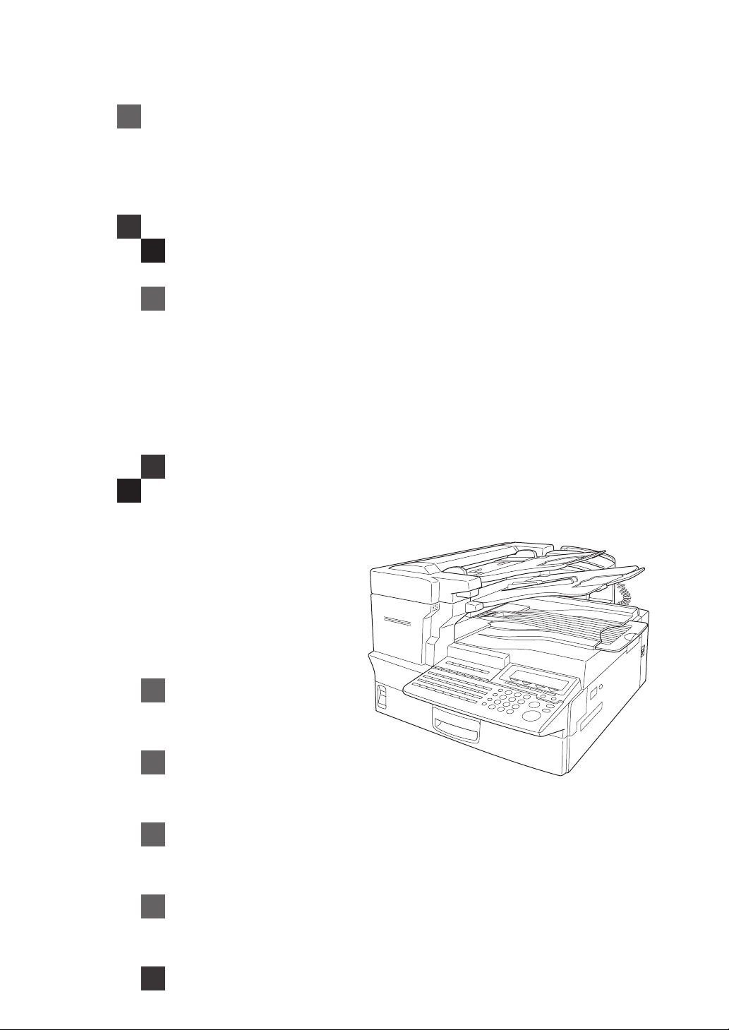
3699/9980 Fax
OPERATING INSTRUCTIONS
Read this manual carefully before you use this product and keep it handy for future
reference.
For safety, please follow the instructions in this manual.
Page 2

Introduction
This manual contains detailed instructions on the operation and maintenance of this machine. To get
maximum versatil ity from this ma chine all opera tors sho uld careful ly read an d follow the ins tructi ons in
this manual. Please keep this manual in a handy place near the machine.
Please read the Safety Information before using this machine. It contains important information related
to USER SAFETY and PREVENTING EQUIPMENT PROBLEMS.
Notes:
Some illustrations might be slightly different from your machine.
Certain options migh t no t be av ail abl e in some countries. For details , pl eas e c ontact your local dealer.
Laser Safety:
CDRH Regulations
This equipment complies with requirements of 21 CFR subchapter J for class 1 laser products. This
equipment contains a 5 m illiw att,76 5-805 na nomete r wave length , GaAlAs laser di ode. Thi s equipme nt
does not emit hazardous light, since the beam is totally enclosed during customer all modes of operation and maintenance.
Caution:
Use of controls or adjus tment s or perfo rmanc e of pr ocedures other tha n those speci fied in this m anual
may resul t in hazardous laser radiation exposur e.
Notes:
Two kinds of size notation are employed in this manual. With this machine refer to the inch version.
For good copy quality, Savin recommends that you use genuine toner.
Savin shall not be responsi ble for any damage or expens e that mi ght resul t from the us e of parts ot her
than genuine parts in your Savin offi ce product.
Power Source:
AC115V, 60Hz
Please be sure to connect the power cord to a power source as above. For details about the power
source.
Page 3

USA
❖
FCC Requirements
1. This equipment compl ies with Par t 68 of the FCC ru les. On the cover of this equipment is a label
that contains, among other information, the FCC registration number and ringer equivalence
number (REN) for this equipment. If requested, this information must be provided to the telephone company.
2. This equipment uses the following USOC jack: RJ11C
3. The REN is used to determine the quantity of devices which may be conne cted to the tele phone
line. Excessive REN 's on th e tele phone l ine m ay res ult in t he dev ices not ring ing in respon se to
an incoming call. In most, but not all areas, the sum of the REN's should not exceed five (5.0).
Contact the telephone company to determine the maximum REN for the calling area.
4. If this equipment causes harm to the telephone network, the telephone company will notify you
in advance that temporary discontinuance of service may be required. If advance notice is not
practical, the tele pho ne co mp any w il l n oti fy the customer as soon as p os sib le. Also, you will be
advised your right to file a complaint with the FCC if you believe it is necessary.
5. The telephone company may make changes in its facilities, equipment, operations, or procedures that could affect the operation of the equipment. If this happens, the telephone company
will provide advance notice in order to make necessary modifications in order to maintain uninterrupted service.
6. In the event of operation problems (document jam, copy jam, communication error indication),
refer to the solving problems section in this manual.
7. If you cannot correct the problem, please contact the SAVIN CORPORATION at 1-203-9675000 for repair and warranty informati on. If it is causing ha rm to the telephone netw ork, the telephone company may request you to disconnect the equipment from the network until the problem is resolved.
8. This equipment cannot be used telep hone comp any-provi ded coin s ervice. C onnectio n to Party
Line Service is subject to state tariffs.
❖
WHEN PROGRAMMING EMERGENCY NUMBERS AND/OR MAKING TEST CALLS TO
EMERGENCY NUMBERS:
1. Remain on the line and briefly explain to the dispatcher the reason for the call before hanging up.
2. Perform such activities in the off-peak hours, such as early morning hours or late evenings.
CANADA
The Industry Canada label identifies certified equipment. This certification means that the equipment
meets telecommunications network protective, operational, and safety requirements as prescribed in
the appropria te Termin al Equ ipm ent Te chni cal Re quir emen ts docu men t(s) . The de part ment do es no t
guarantee the equipment will operate to the user's satisfaction.
Before installing this eq uipment, us ers sho uld ensu re that it is pe rmiss ible to be conn ected to th e facilities of the local telecommunications company. The equipment must also be installed using an acceptable method of connection. The customer should be aware that compliance with the above conditions
may not prevent degradation of service in some situations.
Repairs to certified equipment should be coordinated by a representative designated by the supplier.
Any repairs or alterations mad e by the user to this equ ipment, or equip ment malfunct ions, may give the
telecommunications company cause to request the user disconnect the equipment.
User should ensure for their own protection that the electrical ground connections of the power utility,
telephone lines, and internal metallic water pipe system, if present, are connected together. This precaution may be particularly important in rural areas.
Caution: Users should not attempt to make such connections themselves, but should contact the appropriate electric inspection authority, or electrician, as appropriate.
The Ringer Equivalen ce Number (R EN) assigned to each t erminal d evice prov ides an indication of the
maximum number of terminals allowed to be connected to a telephone interface. The termination on
an interface may consist of any combination of device subject only to the requirement that the sum of
the Ringer Equivalence Numbers of all the devices does not exceed 5.
In accordance with IEC 60417, this machine uses the following symbols for the main power switch:
a
means POWER ON.
b
means POWER OFF.
Page 4

Notice
Note to users i n the United States of
America
Notice:
-
This equipment has been tested and
found to comply with the limits for a
Class B digital device, pursuant to
Part 15 of the FCC Rules. These limits
are designed to provide reasonable
protection against harmful interference in a residential installation. This
equipment generates, uses and can
radiate radio frequency energy and, if
not installed and used in accordance
with the instructions, may cause
harmful interference to radio communications. However, there is no guarantee that interference will not occur
in a particular installation. If this
equipment does cause harmful interference to radio or television reception, which can be determined by
turning the equipment off and on, the
user is encouraged to try to correct
the interference by one more of the
following measures:
• Reorient or relocate the receiving
antenna.
• Increase the separation between
the equipment and receiver.
Warning
-
Changes or modifications not expressly approved by the party responsible for compliance could void
the user's authority to operate the
equipment.
This device complies with Part 15 of
FCC Rules.
Operation is subject to the following
two conditions:
A
This device may not cause harmful
interference, and
B
This device must accept any interference received,
including interference that may cause
undesired operation.
Ricoh Corporation, 5 Dedrick Place,
West Caldwell, NJ 07006
973-882-2000
Properly shielded and grounded ca-
bles and connectors must be used for
connections to host computer (and/
or peripheral) in order to meet FCC
emission limits.
Note to users in Canada
• Connect the equipment into an
outlet on a circuit different from
that to which the receiver is connected.
• Consult the dealer or an experienced radio /TV technician for
help.
Note:
-
This Class B digital apparatus complies with Canadian ICES-003.
i
Page 5

Remarque concernant les utilisateurs au
Canada
It is therefore strongly recommended
that the equipment is set to use DTMF
signalling for access to public or private emergency services. DTMF signalling also provides faster call set up.
Avertissement:
-
Cet appareil numérique de la classe B
est conforme à la norme NMB-003 du
Canada.
Notice about the Telephone Consumer
Protection Act (Valid in USA only).
The Telephone Consumer Protection
Act of 1991 among other things makes
it unlawful for any person to send any
message via a telephone fax machine
unless such message clearly contains
in a margin at the top or bottom of
each transmitted page or on the first
page of the transmission, the date and
time it is sent and an identification of
the business, other entity, or other individual sending the message and the
telephone number of the sending machine or such business, other entity or
individual. This information is transmitted with your document by the TTI
(Transmit Terminal Identification) feature. In order for you to meet the requirement, your machine must be
programmed by following the instructions in the accompanying Operation
Manual. In particular, please refer to
the chapter of Installation. Also refer
to the TTI (Transmit Terminal Identification) programming procedure to enter the business identification and
telephone number of the terminal or
business. Do not forget to set the date
and time.
• Do not use this product near water,
for example, near a bath tub, wash
bowl, kitchen sink or laundry tub,
in a wet basement or near a swimming pool.
• Avoid using a telephone during an
electrical storm. There may be a remote risk of electric shock from
lightning.
• Do not use a telephone in the vicinity of a gas leak to report the leak.
Thank you.
Although this equipment can use ei-
ther loop disconnect or DTMF signalling, only the performance of the
DTMF signalling is subject to regulatory requirements for correct operation.
ii
Page 6

Safety Information
R
R
When using your equipment, the following safety precautions should always be
followed.
Safety During Operation
In this manual, the following important symbols are used:
WARNING:
CAUTION:
Indicates a potentially hazardous situation which, if instructions
are not followed, could result in death or serious injury.
Indicates a poten tially hazar dous situation which, if inst ructions are n ot
followed, may result in minor or moderate injury or damage to property.
iii
Page 7

R
WARNING:
•
Connect the power cord directly into a wall outlet and never use an extension cord.
•
Disconnect the power plug (by pulling the plug, not the cable) if the
power cable or plug becom es frayed or otherwise damaged.
•
To avoid hazardous electric shock or laser radiation exposure, do not
remove any covers or screws other than those specified in this manual.
•
Turn off the powe r and disconnect the power plug (by pu lling the plug,
not the cable) if any of the following conditions exists:
•
You spill something into the equipment.
•
You suspect that your equipment needs service or repair.
•
Your equipment's cover has been damaged.
•
Do not incinerate spilled tone r or used toner. Toner dust might igni te
when exposed to an open flame.
•
Disposal can take place at our authorized dealer or at appropriate collection sites.
•
Dispose of the used toner cartridge in accordance with the local regulation.
iv
Page 8

R
CAUTION:
Protect the equipment from dampness or wet weather, such as rain, snow,
•
and so on.
Unplug the power cord from the wall outlet before you move the equipment.
•
While moving the equipment, you should take care that the power cord will
not be damaged under the equipment.
When you disconnect the power plug from the wall outlet, always pull the
•
plug (not the cable).
Do not allow paper clips, staples, or other small metallic objects to fall inside
•
the equipment.
Keep toner (used or unused) and toner cartridge out of the reach of children.
•
For environmental reasons, do not dispose of the equipment or expended
•
supply waste at household waste collection points. Disposal can take place
at an authorized dealer or at appropriate collection sites.
The inside of the machine could be very hot. Do not touch the parts with a
•
label indicating the “hot surface”. Otherwise it could cause a personal burn.
Our products are engineered to meet high standards of quality and function-
•
ality, and we recommend that you only use the expendable supplies available at an authorized dealer.
v
Page 9

Important Safety Instructions
Grounding
In order to prevent potentially hazardous electrical shock, provide means of
connecting to the protective grounding conductor in the building, wiring those
grounding conductors of power cable and 3 pins plug.
Notice
Do not use this product near water, for example, near a bath tub, wash bowl,
kitchen sink or laundry tub, in a wet basement or near a swimming pool.
Avoid using a telephone during an electrical storm.There may be a remote risk
of electric shock from lightning.
Do not use a telephone in the vicinity of a gas leak to report the leak.
vi
Page 10

Energy Star Program
As an ENERGY STAR Partner, we have determined that this machine model meets the ENERGY STAR Guidelines for energy efficiency.
The ENERGY STAR Guidelines intend to establish an international energy-saving system for developing and introducing energy-efficient office equipment to deal with environmental issues, such as global warming.
When a product meets the ENERGY STAR Guidelines for energy efficiency, the Partner shall place the ENERGY STAR logo onto the machine model.
This product was designed to reduce the environmental impact associated with office
equipment by means of energy-saving features, such as Low-power mode.
• Low-power Mode
This product automatically lowers its power consumption 1 minute after the last
hard copy has been completed. (In this mode, printing a received fax and printing are available.)
To exit Low-power mode, press the
{
Clear Modes/Energy Saver
}
key.
The machine returns to the ready condition in about 30 seconds.
For how to change the default interval before entering Low-power mode, see
“Entering Energy Saver Mode”
P.26
❖
Specification
Low-power mode Power consumption 2.0Wh
Default Time 5min.
Recycled Paper
-
.
(model ****)
Please contact your sales or service representative for recommended recycled
paper types that may be used in this machine.
vii
Page 11

How to Read this Manual
R
R
How to Read this Manual
Symbols
In this manual, the following symbols are used:
WARNING:
This symbol indicates a potentially hazardous situation that might result in
death or serious injury when you misuse the machine without following the instructions under this symbol. Be sure to read the instructions, all of which are described in the Safety Information section.
CAUTION:
This symbol indicates a potentially hazardous situation that might result in minor or moderate injury or property damage that does not involve personal injury
when you misuse the machine without following the instructions under this
symbol. Be sure to read the instructions, all of which are described in the Safety
Information section.
* The statements above are notes for your safety.
Important
If this instruction is not followed, paper might be misfed, originals might be
damaged, or data might be lost. Be sure to read this.
Preparation
This symbol indicates the prior knowledge or preparations required before operating.
Note
This symbol indicates precautions for operation, or actions to take after misoperation.
Limitation
This symbol indicates numerical limits, functions that cannot be used together,
or conditions in which a particular function cannot be used.
Reference
This symbol indicates a reference.
[]
Keys that appear on the machine's panel display.
{}
Keys built into the machine's operation panel.
viii
Page 12

Frequently Asked Questions
How do I check whether
a fax transmission was
successful or not?
Check the communication result
on the display.
⇒
P.136
“Checking the Transmission
Result (TX Status)”
How do I confirm exactly
where my fax is being
sent?
With Immediate Transmission
you can monitor the status of the
transmission at the machine.
⇒
“Immediate Transmission”
P.55
Is it possible to specify
several destinations at
once?
Yes. Storing numbers in a Group
beforehand lets you quickly and
easily specify multiple destinations
in a single operation.
⇒
“Dialing with Groups”
P.76
How can I quickly
recognize received
messages?
Have each page of received
documents automatically marked.
⇒
“Checkered Mark”
P.98
I have to send a fax at a specific time,
but I will not be in the office then.
What can I do?
Specify the transmission time
to suit you or the other party.
⇒
P.104
“Send Later”
Is there any way I can
cut down on my
telephone bill a little?
Specify messages to be sent
automatically at an off-peak time
when telephone charges are
cheaper.
⇒
P.104
“Send Later”
Can I redial a number?
Yes. The machine remembers
the last 10 destinations so you
do not have to enter recently
dialed numbers again.
⇒
“Redialing Numbers”
P.77
ix
Page 13

TABLE OF CONTENTS
1.Getting Started
Guide to Components............................................................................... 1
Main Body..................................................................................................... 1
Internal View ................................................................................................. 4
Operation Panel......................................................................................... 6
Display Layout........................................................................................... 9
Display and key Operations.......................................................................... 9
Example Displays.................................................................................... 11
Standby Display.......................................................................................... 11
Communication Display ................. ............................................................. 11
Display Prompts.......................................................................................... 11
Setup......................................................................................................... 13
Introduction .................. ......................................................................... ...... 13
Choosing the Machine Location.................................................................. 13
Installing the Machine ................................................................................. 13
Loading Paper............................................................................................. 17
Adjusting Initial Settings................................................. ............................. 19
Handy Functions .................... ..... .... .......................................... ..... ..... .... 25
Energy Saver Mode .................................................................................... 25
Adjusting the Printing Density..................................................................... 27
Boxes.............................. ............................................................................ 27
Restricted Access ............................................. .......................................... 29
TX/RX File Save Function........................................................................... 30
Multi-Port Unit (Option) ............................................................................... 30
Acceptable Types Of Documents.......................................................... 32
Acceptable Document Sizes....................................................................... 32
Paper Size and Scanned Area.................................................................... 33
How to Set a Document.......................................................................... 35
Direction in Which Original is Set................................................................ 35
Setting Documents in the Auto Document Feeder (ADF)........................... 35
Setting Paper in the Document Bypass Tray.............................................. 36
Recommended Paper.............................................. ................................ 38
Acceptable Copy Paper Sizes and Types ................................................... 38
Unacceptable Paper Types......................................................................... 38
Changing the Paper Size........................................................................ 39
Changing the Paper Size in the Main Paper Tray....................................... 39
Changing the Paper Size in the Optional Paper Supply Unit...................... 41
2.Sending a Fax Message
Overview................................................................................................... 45
Overview............................................................................. ........................ 45
x
Page 14

Memory Transmission............................................................................ 46
File Reserve Report (Memory Transmission) ............................................. 50
Communication Result Report (Memory Transmission) ............................. 50
Communication Failure Report ................................................................... 51
Canceling a Memory Transmission....................................................... 52
Mission Before the Document is Scanned in .............................................. 52
Canceling a Transmission while the Document is Being Scanned in ......... 52
Canceling a Transmission while the Machine is Dialing ............................. 53
Canceling a Transmission while the Message is Being Sent...................... 53
Canceling a Fax that is Awaiting Transmission........................................... 54
Immediate Transmission............ .... .......................................... ..... ..... .... 55
Transmission Result Report ....................................................................... 56
Canceling an Immediate Transmission................................................. 58
On-Hook Dial............................................................................................ 59
Using On Hook Dial with ISDN.................................................................... 59
Manual Dial..................... .... .......................................... ..... ..... .................. 61
Scan Settings........................................................................................... 62
Resolution................................................................................................... 62
Image Density...... ....................................................................................... 63
Halftone............................................................................................ ........... 63
Mixing Scan Settings in a Multiple Page Document.................................... 63
Selecting the Line.................................................................................... 65
How to Select the Line................................................................................ 66
Dialing....................................................................................................... 67
Number
Dialing with Quick Dials............................................................................... 73
Dialing with Speed Dials ............................................................................. 74
Dialing with Groups..................................................................................... 76
Redialing Numbers......................... ............................................................. 77
Keys.............................................................................................. 67
Sending a Fax Using a Program............................................................ 79
Transmission Features........................................................................... 81
No Document, No Dial ................................................................................ 81
Stamp.......................................................................................................... 81
Auto Reduction............................................................................................ 81
Duplex Original Settings.............................................................................. 82
Label Insertion............................................................................................. 83
Auto Document ........................................................................................... 83
TTI/CIL Print ................................................................................................ 83
ID Transmission.......................................................................................... 84
Skip Transmission ....................................................................................... 84
Backup File Transmission........................................................................... 85
JBIG Transmission................. ..................................................................... 85
xi
Page 15

3.Receiving a Fax Message
Immediate Reception....................................................... ..... .... .............. 87
Memory Reception .................................................................................. 88
Substitute Reception............................................................................... 89
Screening Messages From Anonymous Senders.................. ..................... 89
Selecting the Reception Mode............................................................... 91
Fax Mode (Auto Receive Mode) ................................................................. 91
Telephone Mode ......................................................................................... 91
How to Select the Reception Mode............................................................. 91
Reception Functions............................................................................... 92
Transfer Station........................................................................................... 92
Transfer Result Report................................................................................ 93
Remote Transfer......................................................................................... 93
Remote Transfer with UUI........................................................................... 95
ID Reception ............................................................................................... 96
JBIG Reception........................................................................................... 96
Authorized Reception.................................................................................. 96
Specified Tray............................................................................................. 96
Forwarding............................................................................. ..................... 97
Printing Functions................................................................................... 98
Checkered Mark........................ .................................................................. 98
Center Mark ................................................................................................ 98
Reception Time............... ............................................................................ 98
Collate................................................................. ........................................ 98
Two In One.................................................................................................. 99
Image Rotation.................................................................... ........................ 99
Rotate Sort................................................................................................ 100
Page Separation and Length Reduction (Not Available in Some Countries)...
100
TSI Print.................................................................................................... 101
CIL/TID Print ............................................................................................. 101
When there is No Paper of the Correct Size............................................. 101
4.Advanced Transmission Features
Overview................................................................................................. 103
Overview................................................................................................... 103
Send Later............................................. ..... .......................................... .. 104
Confidential Transmission................................................................... 106
Personal Code Transmission............................................................... 108
Entering a Personal Code with a Quick Dial Key...................................... 109
SUB Code Transmission with the Mode Key...................................... 111
SEP Code Polling Reception................................................................ 114
Polling Reception.................................................................................. 117
xii
Page 16

File Reserve Report (Polling Reception)................................................... 119
Communication Result Report (Polling Reception)............................. ...... 119
Polling Transmission............................................................................ 120
Polling Transmission Clear Report............................................................ 123
Transfer Request................................................................................... 124
Specifying an End Receiver...................................................................... 126
TTI Print.................................................................................................. 127
5.Communication Information
Checking and Canceling Transmission Files..................................... 129
Canceling a Transmission......................................................................... 129
Printing a File............................................................................................ 130
Checking and Editing a File ...................................................................... 131
Printing a List of Files in Memory (Print TX File List)........................ 135
Checking the Transmission Result (TX Status).................................. 136
Checking the Reception Result (RX Status)....................................... 137
Printing a Confidential Message.......................................................... 138
Confidential File Report............................................................................. 139
Printing a File Received with Memory Lock........................................ 140
Printing the Journal............................................................................... 142
Displaying the Files in Memory............................................................ 145
TX/RX File Save ...................... ..... .... ..... .......................................... ..... .. 146
Searching Memory for Sent Faxes............................................................ 146
Searching Memory for Received Faxes.................................................... 149
Disk File Search List/Visual List................................................................ 152
Printing Files ............................................................................................. 152
Deleting Files ............................................................................................ 153
Box File Manager Functions................................................................. 154
Printing Personal Box Messages.............................................................. 154
Storing Messages in Information Boxes.................................................... 155
Printing Information Box Messages .......................................................... 156
Deleting Information Box Messages ......................................................... 158
6.Copying
Copying.................................................................................................. 161
7.Troubleshooting
Solving Problems.................................................................................. 163
Error Messages and Their Meanings................................................... 165
Clearing Document Jams..................................................................... 166
Clearing Document Jams in the ADF........................................................ 166
xiii
Page 17

Clearing Document Jams in the Bypass Tray........................................... 167
Clearing Paper Jams............................................................................. 168
Clearing Paper Jams in the Fusing Unit.................................................... 168
Clearing Paper Jams in the Main Paper Tray .......................... ................. 169
Clearing Paper Jams in the Optional Paper Supply Unit .......................... 170
Replacing the Toner Cartridge............................................................. 172
Indicators ............................................................................................... 174
When the
i
When the Confidential Reception/Memory Lock Indicator is Lit or Flashing
174
M
When the Cover Open Warning Indicator is Lit..................................... 175
x
When the Paper Jammed Indicator is Lit.............................................. 175
D
When the Add Toner Indicator is Lit or Flashing................................... 175
B
When the Paper Supply Indicator is Lit................................................. 176
L
When the Call Service Indicator is Lit..................................................... 176
Receive File
Indicator is Lit...................................................... 174
When an Error Report is Printed.......................................................... 177
When Power is Turned Off or Fails...................................................... 178
8.Fax Features
Fax Features .......................................................................................... 179
Program/Delete Menu............................................................................ 180
Registering Quick Dials ............................................................................. 180
Deleting Quick Dials .................................................................................. 183
Registering Groups................................................................................... 185
Deleting Groups........................................................................................ 194
Registering Speed Dials............................................................................ 195
Deleting Speed Dials................................................................................. 198
Storing Keystroke Programs. .................................................................... 199
Deleting a Keystroke Program.................................................................. 203
Registering Auto Documents .................................................................... 204
Deleting an Auto Document...................................................................... 207
Reports/Lists.......................................................................................... 209
Assigning User Function Keys............................................................ 211
Registering/Editing the Contents of a User Function Key......................... 211
Programming a User Function Key on the Job......................................... 212
Functions You Can Store in a User Function Key..................................... 213
Utilizing User Function Keys..................................................................... 213
Deleting Functions Stored in User Function Keys..................................... 214
Fax On Demand..................................................................................... 216
Registering/Editing Fax On Demand Documents ..................................... 216
Deleting Fax On Demand Documents ...................................................... 218
Printing Fax On Demand Documents ....................................................... 220
Printing the Fax On Demand List.............................................................. 221
Printing the Fax On Demand Access Report............................................ 222
Fax On Demand Recorded Messages...................................................... 223
xiv
Page 18

9.Key Operator Tools
Key Operator Tools............................................................................... 229
System Settings..................................................................................... 230
Counters.................................................................................................... 230
Monitor Volume......................................................................................... 231
Adjusting the Display Contrast.................................................................. 232
Date/Time.................................................................................................. 233
Summer Time/DST ................................................................................... 233
Registering the Economy Transmission Time .......................................... 233
Night Timer................................................................................................ 234
Changing the User Parameters................................................................. 236
File Retention............................................................................................ 242
RTI/TTI...................................................................................................... 243
G3-1 Analog Line...................................................................................... 243
G3-2 Analog Line...................................................................................... 245
G3 Digital Line........................................................................................... 246
G4 Digital Line........................................................................................... 248
Registering ID Codes................................................................................ 250
Transfer Report......................................................................................... 252
Network Settings....................................................................................... 253
System Parameter Transmission.............................................................. 253
Memory File Transfer................................................................................ 254
Reset PM Counters................................................................................... 255
RDS (Remote Diagnostic System)............................................................ 257
Initial Set Up........................................................................................... 259
Opening the Initial Set Up Menu............................................................... 260
Collate....................................................................................................... 260
(Printing Multiple Copies of Messages From Certain Senders)
Authorized Reception................................................................................ 262
(Blocking Out Messages from Certain Senders)
Specified Tray........................................................................................... 265
(Having Messages from Certain Senders Printed on Different Paper)
Forwarding................................................................................................ 268
(Having Messages From Certain Senders Forwarded)
Deleting Forwarding Addresses................................................................ 272
Deleting Specified Senders (Forwarding) ................................................. 273
Printing the Specified Sender List (Forwarding)........................................ 275
Memory Lock............................................................................................. 276
(Having Messages from Certain Senders Stored in Memory Instead of Being
Printed Out)
TX/RX File In HD....................................................................................... 279
(Having Messages from Certain Senders Stored in Memory)
Deleting Specified Senders....................................................................... 282
General Procedure for Deleting Specified Senders
Printing the Specified Sender List............................................................. 283
(General Procedure for Printing a List of Registered Specified Senders)
How to Print Specified Sender List............................................................ 284
xv
Page 19

Backup File Transmission Settings........................................................... 284
(Specifying a Destination to Send Backups of Faxes)
Program Scan Area................................................................................... 286
(Setting the Scan Area)
Box Settings........................................................................................... 289
Registering/Editing Personal Boxes.......................................................... 289
Deleting Personal Boxes ........................................................................... 292
Registering/Editing Information Boxes...................................................... 294
Deleting Information Boxes....................................................................... 295
Registering/Editing Transfer Boxes........................................................... 297
Deleting Transfer Boxes............................................................................ 300
Printing the Box List.................................................................................. 301
10.Entering and Modifying Text
Available Characters............................................................................. 303
Keys........................................................................................................ 304
How To Enter Text................................................................................. 306
Entering Letters......................................................................................... 306
Entering Symbols...................................................................................... 306
Entering Numbers..................................................................................... 306
Deleting Characters .................................................................................. 307
11.Maintaining Your Machine
Maintaining the Machine....................................................................... 309
Cleaning the Document Transport Mechanism......................................... 309
Cleaning the Copy Paper Transport Mechanism...................................... 310
Cleaning the Registration Roller ............................................................... 311
Maintenance Kits....................................................................................... 311
12.Appendix
Options................................................................................................... 317
Memory Cards........................................................................................... 317
Optional Function Upgrade Card .............................................................. 317
Optional Fax On Demand ......................................................................... 318
Installing the Memory Cards, Optional Function Upgrade Card and Fax On De-
mand Card ................................................................................................ 318
Optional G3 Unit........................................................................................ 319
Optional G4 Unit........................................................................................ 319
Optional Handset ...................................................................................... 320
Optional NIC FAX Kit ................................................................................ 320
Optional PC-FAX Expander...................................................................... 321
Optional Printer Interface.......................................................................... 321
Other Options............................................................................................ 321
Function List.......................................................................................... 322
xvi
Page 20

Advanced Transmission Features............................................................. 322
Communication Information...................................................................... 323
Fax Features............................................................................................. 324
Key Operator Tools................................................................................... 326
Specifications........................................................................................ 330
Certification Label................................................................................. 331
INDEX...................................................................................................... 332
xvii
Page 21

xviii
Page 22
1. Getting Started
Guide to Components
Main Body
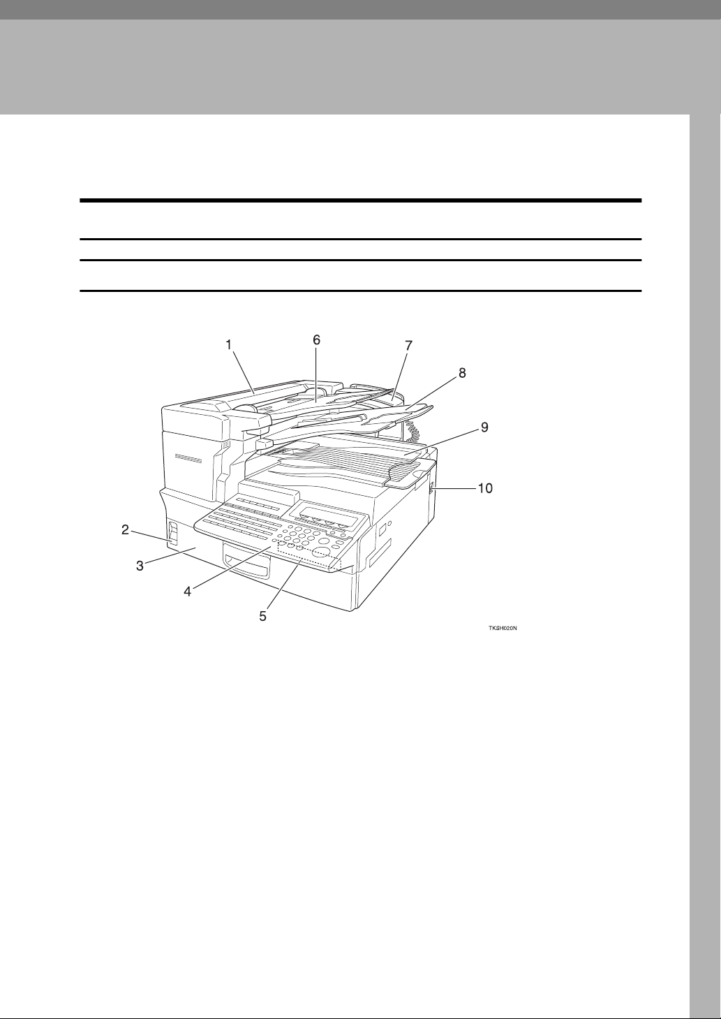
Front view
1. Auto Document Feeder (ADF)
Set multi-page documents here to have
them automatically scanned in one page
at a time.
2. Paper Supply Indicator
Lights red when paper has run out.
3. Main Paper Tray
Load blank paper here.
4. Operation Panel
5. Optional Card Insertion Slots
Left slot—insert the optional Function
Upgrade Card here
Right slot—insert the optional Memory
Card or optional Fax On Demand Card
here
6. Document Tray
7. Optional Handset
8. Document Output Tray
Scanned documents are stacked here.
9. Output Tray
Copies and incoming faxes are stacked
here.
10. Power Switch
Use to turn the power on or off.
1
Page 23
1
Getting Started
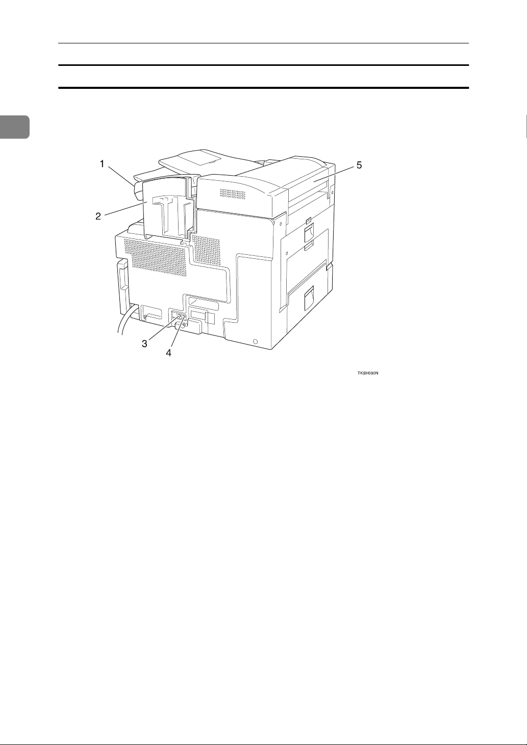
Rear view
1. Optional Handset
2. Manual Pocket
Keep the Quick Guide here.
3. Optional Handset/External Tele-
phone Connector
4. Telephone Line Connector
5. Document Bypass Tray
Load non-standard size blank paper
here.
2
Page 24
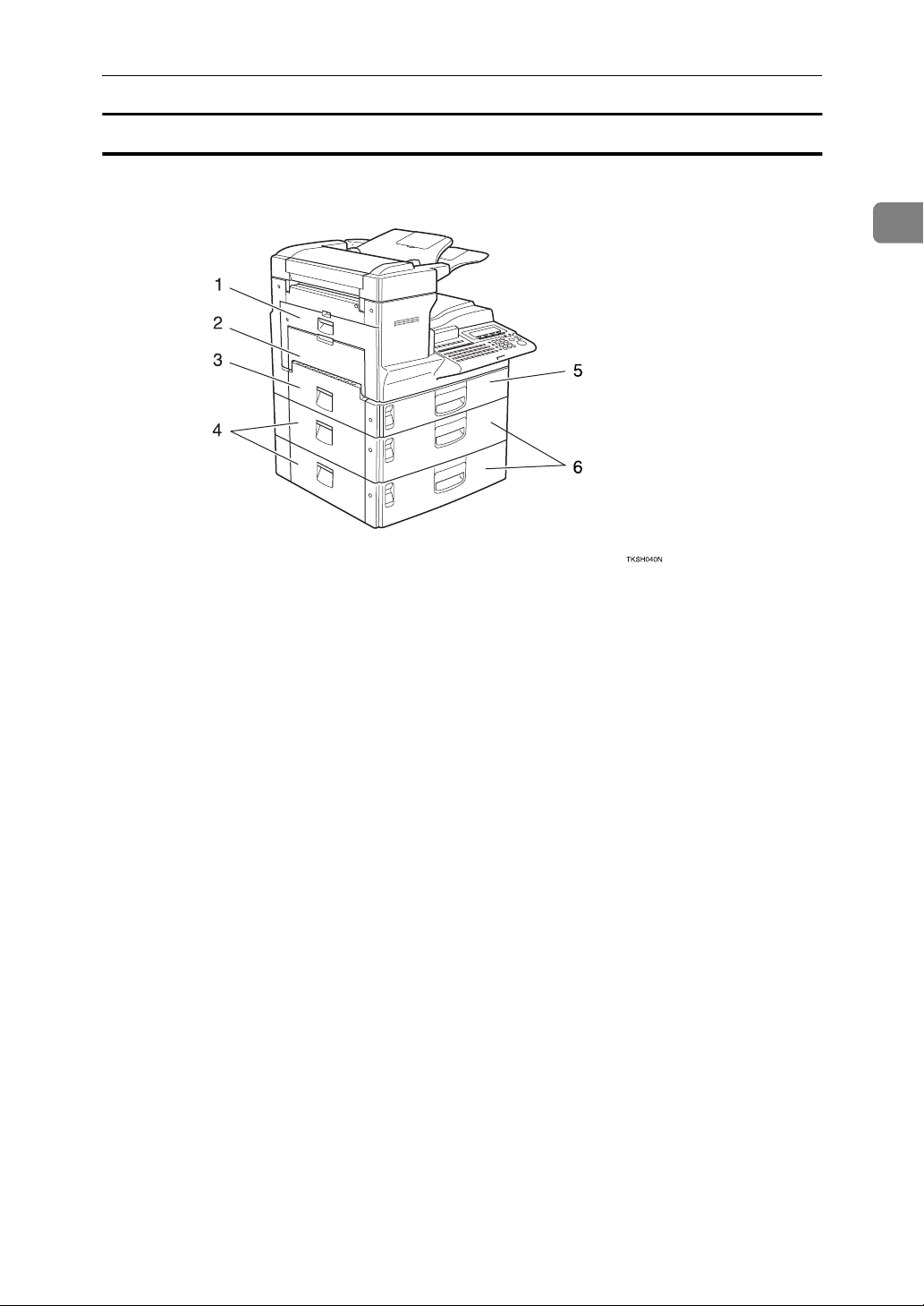
When the optional Paper Supply Unit is installed
Guide to Components
1
1. Main Side Cover
Open this cover when changing the toner
cartridge or installing the fusing unit
maintenance kit.
⇒ P.172
⇒ P.313
tenance Kit”
“Replacing the Toner Cartridge”
“Installing the Fusing Unit Main-
2. Bypass Tray
Use when the optional Printer Interface is
installed. ⇒ Please refer to the Printer Interface manual for details.
3. Paper Tray Side Cover
Open to clear paper jams.
⇒ P.168
“Clearing Paper Jams”
4. Paper Supply Unit Side Cover
Open to clear paper jams.
⇒ P.170
tional Paper Supply Unit”
“Clearing Paper Jams in the Op-
5. Main Paper Tray
6. Optional Paper Supply Unit
Provides an extra paper source in addition to the main paper tray. You can install up to two of these units.
3
Page 25
Getting Started
Internal View
1
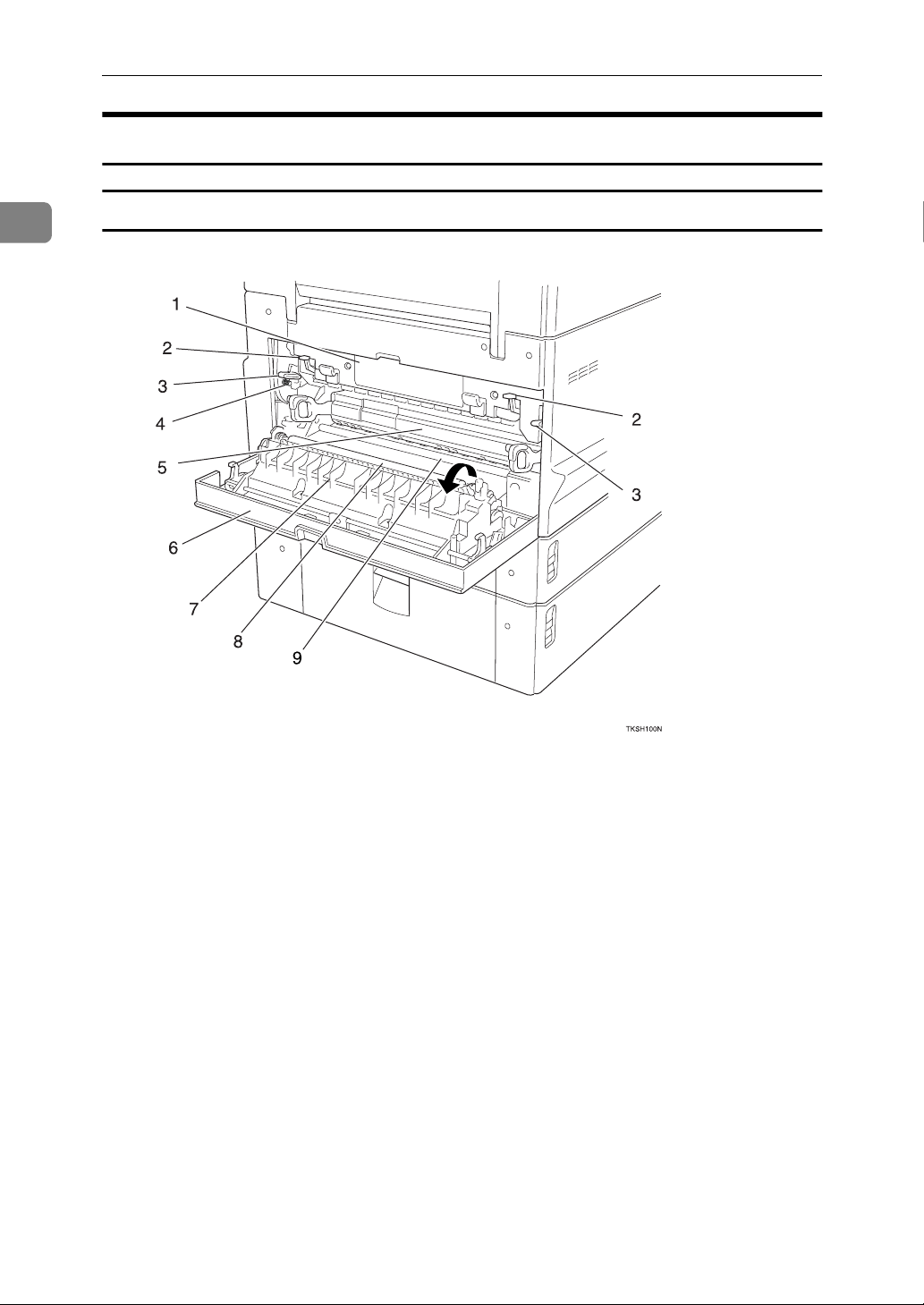
View with Main Side Cover open
1. Fusing Unit
Fuses the toner to the paper. Replace this
unit if a message asking you to do so appears on the display.
⇒ Installing the fusing unit maintenance
kit.
2. Pressure Release Levers
Lower these transparent levers to remove
jammed paper.
3. Fusing Unit Fixed Levers
Lower these levers when installing the
fusing unit maintenance kit.
4. Screw
Remove these green screws when lowering the fusing unit fixed levers to install
the fusing unit maintenance kit.
4
5. Toner Cartridge
Replace the toner cartridge when a message appears on the display instructing
you to do so.
⇒ P.172
“Replacing the Toner Cartridge”
6. Main Side Cover
Open to clear paper jams and replace the
toner cartridge etc.
7. Transfer Roller Cover
Open to replace the transfer roller.
⇒ P.313
tenance Kit”
“Installing the Fusing Unit Main-
8. Transfer Roller
Replace when installing the fusing unit
maintenance kit.
⇒ P.313
tenance Kit”
“Installing the Fusing Unit Main-
Page 26
Guide to Components
9. Corona Roller
This feeds the paper. Clean this roller if it
gets dirty.
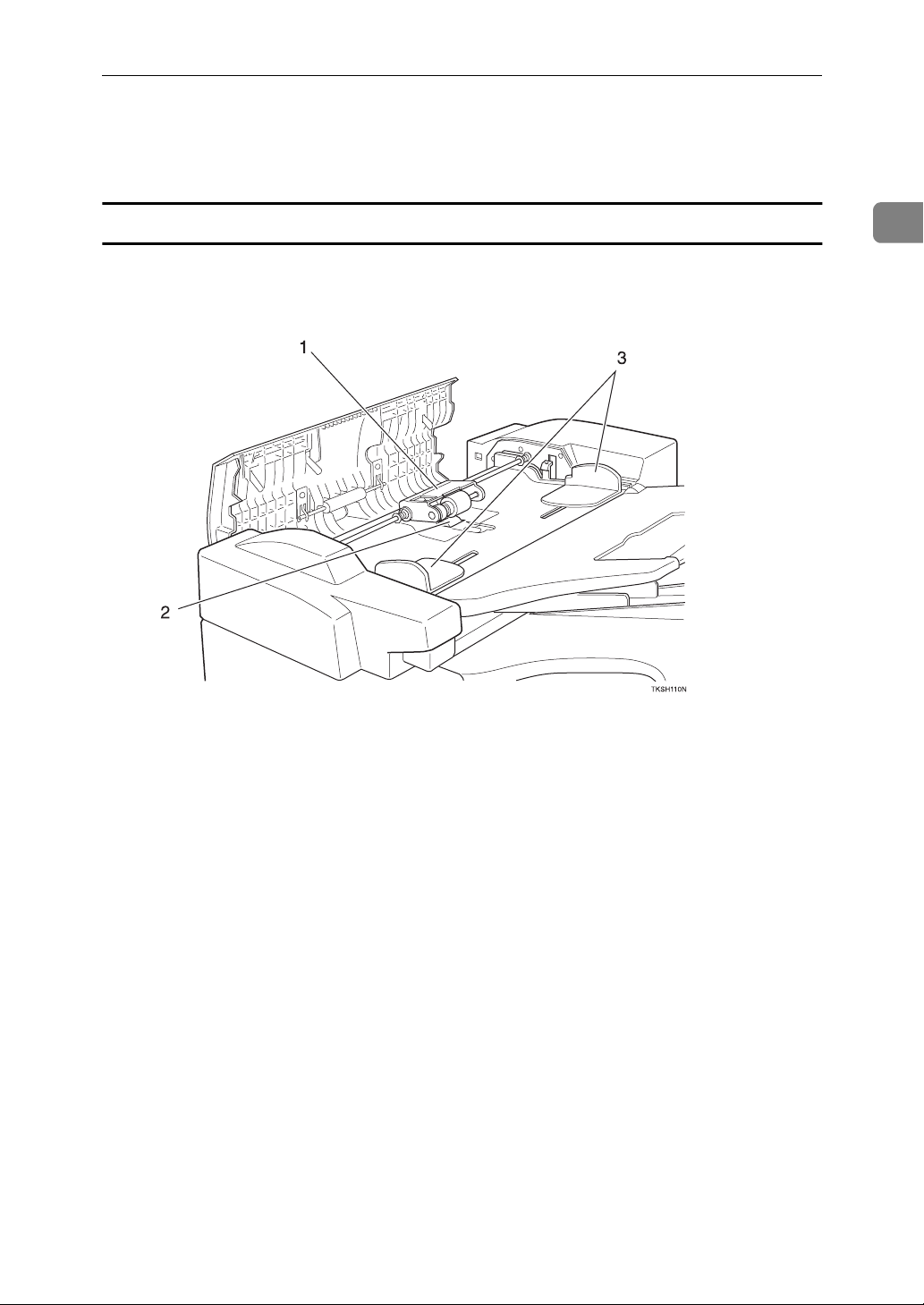
View with the ADF cover open
⇒ P.311
“Cleaning the Registration Roller”
1
1. Feed Unit
Feeds in documents. Replace when installing the ADF unit maintenance kit.
⇒ P.312
nance Kit”
“Installing the ADF Unit Mainte-
2. Separation Roller
Pages are fed in between this roller and
the feed unit. Replace when installing the
ADF unit maintenance kit.
⇒ P.312
nance Kit”
“Installing the ADF Unit Mainte-
3. Document Guides
Adjust these guides to match the size of
your document.
5
Page 27

1
Getting Started
Operation Panel
1. Power Indicator
Lights when power is on. In Low Power
Standby mode this indicator goes out.
2.
❖fOnline Indicator
When the optional Printer Interface is
installed, this indicator shows whether the machine is online (lit) or offline
(unlit).
When online, the machine is ready to
print data received from a PC.
❖mData-in Indicator
When the optional Printer Interface is
installed, this indicator flashes when
the machine is receiving data from a
PC. When lit, the machine is waiting
for data from a PC.
❖
Communicating Indicator
Lights during reception or transmission.
❖
Receive File Indicator
Lights when a message has been received into memory with any function
other than Confidential Reception.
⇒ P.89
“Substitute Reception”
❖iConfidential Reception/Memory
Lock Indicator
Lights when a message has been received into memory with the Confidential Reception function.
⇒ P.138
sage”
Flashes when a message has been received with the Memory Lock function.
⇒ P.140
Memory Lock”
“Printing a Confidential Mes-
“Printing a File Received with
❖MCover Open Warning Indicator
Lights if a cover is open. Make sure all
covers are firmly closed.
6
Page 28

Operation Panel
❖xPaper Jammed Indicator
Lights if paper is jammed. Remove the
jammed paper as instructed on the
display.
❖DAdd Toner Indicator
Flashes when toner is low, lights
when toner has completely run out.
⇒ P.172
tridge”
“Replacing the Toner Car-
❖LCall Service Indicator
Lights to indicate the machine has
broken down. If lit, please contact
your service representative.
3. Display
Displays messages and the status of the
machine.
4.
❖ {
User Tools} Key
Press to access the User Tool settings
and customize various functions to
meet your specific requirements.
⇒ P.179
⇒ P.229
❖
User Function Keys
You can store functions you often use
in these keys and recall them with a
single key press. When shipped, the
following functions are registered by
default:
Key Function
F1
{
}
F2
{
}
F3
{
}
F4
{
}
F5
{
}
⇒ P.211
Keys”
“Fax Features”
“Key Operator Tools”
Journal Print
TTI Print On/Off
Group Dial
Nothing
Nothing
“Assigning User Function
5.
❖
Reception Mode Key
When the indicator above this key is
lit, the machine is in TEL mode. When
it is unlit, the machine is in Auto Receive mode.
⇒ P.91
❖ {
Selects whether a mark is stamped on
scanned documents.
⇒ P.81
❖ {
Press to select G3, G4 or extension.
⇒ P.65
❖ {
Select halftone when faxing or copying photographs or illustrations with
fine gradations. Also can be used for
color documents.
⇒ P.63
❖ {
Press to adjust the brightness of
scanned images when faxing or copying.
⇒ P.63
❖ {
Press to select the level of detail to be
sent.
⇒ P.62
❖ {
Press to select the fax transmission
mode. The indicators above this key
indicate the current mode.
“Selecting the Reception Mode”
Stamp} Key
“Stamp”
Line Selection} Key
“Selecting the Line”
Halftone} Key
“Halftone”
Image Density} Key
“Image Density”
Resolution} Key
“Resolution”
Transmission Mode} Key
6. Quick Dial Key Flip Plate
01
{
Flip down to access Quick Dials
32
}
{
, flip up to access Quick Dials
64
}
{
.
}
{33}
7. Quick Dial Keys
Fax numbers stored beforehand in these
keys can be recalled with a single keypress. Also use to enter characters and
with the Group and Program functions
etc.
⇒ P.73
⇒ P.76
⇒ P.199
“Dialing with Quick Dials”
“Dialing with Groups”
“Storing Keystroke Programs”
1
–
–
7
Page 29

Getting Started
1
8. Status Indicators
These indicators allow you to view the
machine status from a distance.
❖hAlarm
Lights when an error has occurred.
Check the display for details.
⇒ P.165
Meanings”
❖ 0
Communicating
Lights during fax transmission or reception. Also lights when the optional
Printer Interface is installed and data
is being printed.
⇒ Please refer to the optional Printer
Interface manual for details.
9.
{
Speed Dial
Press to specify a destination stored in a
Speed Dial.
⇒ P.74
❖ {
Pause/Redial} Key
Pause—press to insert a small delay
between digits of a fax number. The
first digit of a fax number cannot be a
pause.
⇒ P.68
Redial—press to redial a recently dialed number.
⇒ P.77
“Error Messages and Their
Key
}
“Dialing with Speed Dials”
“Pause”
“Redialing Numbers”
12. Selection Keys
These keys match the keys shown on the
display. Press them to select functions
and choose settings etc.
13. Arrow Keys
Press to move the display cursor and
make function selections.
14.
{
Clear Modes/Energy Saver
• Reset—Cancel the current settings
and return to the standby mode (except when accessing the User Tools).
• Energy Saver—Hold down this key
for about 2 seconds to force the machine to enter Energy Saver mode. The
machine automatically enters Energy
Saver mode about 5 minutes after the
last operation was carried out.
⇒ P.25
15.
Press to stop an Immediate Transmission, scanning of a Memory Transmission, or a report being printed. Also can
be used to delete entered characters.
16.
Press when you wish to make copies.
⇒ P.161
“Energy Saver Mode”
}
Stop
}
Copy
“Copying”
Key
Key
{
{
Key
}
❖ {
On Hook} Key
Use to dial in the same way as a telephone.
⇒ P.59
❖ {
Press to delete a single character when
entering numbers or other characters.
“On-Hook Dial”
Clear} Key
10. Number Keys
Press to enter digits, e.g. when dialing a
fax number.
Start
Key
}
11.
{
Press to send a fax or start printing of a
report etc.
8
Page 30
Display Layout
Display Layout
The operation panel display shows information about the current operation,
function menus and useful messages.
Important
❒
Do not subject the display to a shock or force of more then about 30N (about
3kgf) or it could be damaged.
Note
❒
Selected functions are shown white on black e.g.
❒
Functions you cannot select are shown grayed down e.g.
Display and key Operations
❖
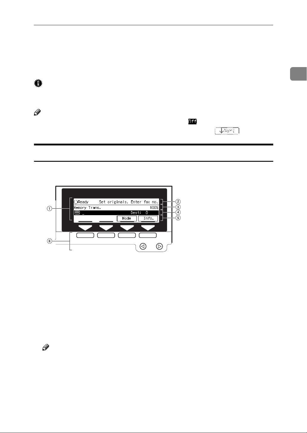
Example 1: Standby display
1
TKSS031N
A
The currently selected function
B
Machine status and messages
C
Amount of free memory
D
Entered destination fax number and number of destinations entered so far
E
Selectable functions or options
F
Press these buttons to select the function or setting name that appears on the
display immediately above each button
Note
❒
Each time you press 0 the selected item moves one position to the left.
❒
Each time you press 1 the selected item moves one position to the right.
9
Page 31

1
Getting Started
❖
Example 2: Menu display
TKSS032N
A
If you select a function, a ' mark will appear next to it.
Note
❒
Functions that are displayed differ according to installed options.
B
Operation status and messages
C
Items or commands you can select.
D
Press these buttons to select the item or command that appears on the display
immediately above each button.
Note
❒
Each time you press 0 the selected item moves one position to the left.
❒
Each time you press 1 the selected item moves one position to the right.
❖
Common keys
Yes][OK
[
No][Cancel
[
[
↑
01
PrevMenu
[
Exit
[
Prev.
]
]
]
Next
][
]
↓
]
Confirm the selected function or entered value, then return
to the previous menu.
Cancel the selected function or entered value, then return to
the previous menu.
If there are more items that cannot fit on the display, use
these keys to scroll through them.
Use to select functions. The currently selected function is
shown black on white.
Return to the previous menu.
Confirm the selected function or entered value, then return
to the standby display.
10
Page 32

Example Displays
Example Displays
The display tells you the machine status and guides you through operations.
Note
❒
Functions that have been selected
are hilighted as shown ( ). Keys
that you can not select are shown
with a dashed outline ( ).
Standby Display
While the machine is in the standby
mode (immediately after it is turned
{
on or after the
}
er
key is pressed), the following dis-
play is shown.
❖
Memory Transmission
❖
Immediate Transmission
Clear Modes/Ener gy Sav-
• If you have not set a document
and are in the sending process,
{
press the
}
Saver
• If you are in User Tools mode,
press the
key.
Clear Modes/Energy
{
User Tools
}
key.
Communication Display
While the machine is communicating
the communication status is displayed.
❖
Display during Memory Transmission
or Memory Reception:
Note
❒
Even when the machine is sending
or receiving a fax message from/
into memory, you can still scan the
next document into memory.
1
❖
Copy mode
Note
❒
To return the machine to standby
mode, perform one of the following:
• If you have set a document and
are in the sending process, remove the document.
❖
Immediate Transmiss i on :
Display Prompts
Depending on the situation, the machine will show various prompts on
the display.
11
Page 33

1
Getting Started
❖
Instructions and requests
❖
Questions
❖
Selections
❖
Status
12
Page 34

Setup
Introduction
Thank you for buying this product.
The Setup section describes how to
choose a suitable location for the machine and install various parts in
preparation for turning on the power.
In addition, it lists the basic settings
that are necessary to get the machine
up and running.
For how to get the most out the advanced features of this product,
please refer to the rest of this manual.
Setup
• Away from areas exposed to corrosive gas
• Dust-free
• Condensation-free
• Temperature in the range 50°F–
89.6°F
• Humidity in the range 15%–80%
• Away from heaters and air conditioners in order to avoid sudden
changes of temperature
• Within 5 yards of a three-pin
grounded power outlet (115 volts,
60 Hz)
1
Important
❒
Before you continue, please take a
few moments to read the safety information to avoid any damage to
the machine or injury to yourself
or others. seeP.iii
tion”
.
“Safety Informa-
Choosing the Machine
Location
For the best possible performance, install your machine in a place which
satisfies the following conditions:
• Not exposed to direct sunlight.
• Well ventilated (air turnover at
least three times per hour). To
avoid buildup of ozone, install the
machine in a large, well-ventilated
room which has an air turnover of
more than 30 cubic yards per hour
per person.
• Level
• Not subject to vibration
• Within the clearance shown below
• At least 11.81" (30 cm) clearance to
the left of the machine is necessary
when clearing paper jams, changing the toner cartridge etc.
Installing the Machine
Fitting the Manual Pocket
Follow the steps below to fit the pocket for storing the Facsimile Quick
Guide.
• Away from other electronic equipment (to avoid interference)
13
Page 35

Getting Started
1
A Squeeze in the release lever to un-
lock the ADF. Then lift up the
ADF cover.
B While holding up the ADF cover,
insert the manual pocket into the
slot provided.
Installing the Document Output Tray and
Document Tray
A Identify the document output
tray (it is bigger than the other
tray).
TKSX040N
B With the frosted side facing up,
bend the document output tray to
insert it into the lower two slots
provided.
C Push down on the left and right
sides of the ADF cover to close it.
Make sure it clicks firmly into
place.
D If you wish to install the optional
handset, fix the handset holder as
shown.
14
TKSX030N
TKSX050N
C Check the orientation of the docu-
ment tray, then bend to insert it
into the lower two slots provided.
TKSX060N
Page 36

Setup
D If you regularly set large docu-
ments, pull out both tray extensions.
TKSX070N
Installing the Toner Cartridge
Important
❒
Be careful not to get toner on your
hands or clothes. If you get toner
on your hands, wash them thoroughly.
to right and backwards and forwards about 7 or 8 times.
1
TKST020N
C Place the toner cartridge on a flat
surface. While supporting the cartridge with one hand, pull the
toner seal horizontally to remove
it.
A Open the main side cover in the
direction of the arrow.
B While holding the cartridge hori-
zontally, shake it gently from left
Important
❒
Using the cartridge without removing the seal could damage
the machine. Always remove
the seal before using a new cartridge.
❒
Be sure to pull the seal horizontally when removing it. Pulling
it from above or below can
cause toner to easily spill out.
❒
Once the seal is removed, toner
can easily spill out, so pay attention not to shake or bump it.
TKST030N
15
Page 37

Getting Started
1
D Grasp the two handles at either
end and push the cartridge into
the machine.
TKST040N
E Close the main side cover making
sure it clicks firmly into place.
Note
❒
The main side cover will not
close properly if the toner cartridge is set into the machine incorrectly. If the cover will not
close, remove the cartridge and
set it again.
• LINE: Telephone line connection
Important
❒
Make sure the modular connector
is the correct type before plugging
it in.
❖
When using a modular type connector
Connecting the machine to the telephone
line
To reduce risk of fire, use only No.26
AWG or larger telecommunication
line cord.
To connect the machine to a telephone line, use a snap-in modular
type connector.
• TEL1: For the optional handset or
external telephone
External
Telephone
Connecting the optional External
Telephone
You can connect the optional handset
or an external telephone to the machine and use it for telephone calls.
Note
❒
Some types of telephone cannot be
connected or may suffer reduced
functionality.
16
Page 38

❖
Specifying the optional handset line
type
Setup
Loading Paper
DPTT
ND1X00E0
The switch on the handset should be
in the appropriate position—TT
(Tone Dialing) or DP (Pulse Dialing).
❖
Adjusting the handset bell volume
Ringer
3
6
9
2
5
8
1
0
4
7
When paper runs out, follow one of
the procedures below to load paper.
Note
❒
For acceptable paper types, directions, sizes and capacity, see P.38
“Recommended Paper”
.
Loading paper in the Main Paper Tray
Important
❒
Before you start, make sure the
machine is not printing copies or
receiving a fax.
❒
Do not reuse stapled paper, or use
conductive paper, such as carbon
paper or silver coated paper.
A Pull out the paper tray as shown.
1
ND1X00E1
Adjust the handset ringer volume using the volume switch.
Connecting the power and turning on
Important
❒
Make sure that the wall outlet is
near the machine and readily accessible.
❒
The wall outlet must be easily accessible.
A Plug the power cord to the power
outlet.
B Turn on the power switch.
17
Page 39

Getting Started
1
B Push down the base plate until it
clicks into place.
C Adjust the dial to match the paper
size.
Important
❒
Do not load a stack of paper that
exceeds the limit mark.
Limitation
❒
You can set up to 250 sheets in
the main paper tray.
E Gently return the paper tray to its
original position.
Loading paper in the optional Paper
Supply Unit
A Pull out the paper unit.
Important
❒
If the dial does not match the
size and direction of loaded paper, parts of printed images
may be missing and paper jams
could occur.
D Prepare the new paper, then in-
sert it under the left and right
metal tabs as shown.
18
B Rotate the dial until the loaded
paper size is shown.
A4
A4
Important
❒
If the deal does not match the
size of loaded paper, parts of
printed images may be missing
and paper jams could occur.
Page 40

Setup
C Prepare the new paper, then in-
sert it under the left and right
metal brackets as shown.
Important
❒
Do not load a stack of paper that
exceeds the limit mark.
Limitation
❒
You can set up to 500 sheets in
the paper unit.
D Gently return the paper unit to its
original position.
Note
❒
Make sure that machine is in
standby mode before following
this procedure. If the standby display is not shown when you start,
the display may become temporarily jumbled up.
A Make sure that the machine is in
standby mode.
Note
❒
If the “Fax Features” or “Key
Op. Tools” screen is shown,
{
press the
other display is shown, press
the
key.
B Press the
User Tools
{
Clear Modes/Energy Saver
{
User Tools
}
key. If any
key.
}
1
}
Adjusting Initial Set tings
After you turn the machine on for the
first time, you need to register the following settings:
• language
• Date and Time
• RTI and TTI
• Line type and CSI
Switching Language
If your native Language is Spanish or
French, you can have the messages
that appear on displays, lists and reports shown in either of these languages instead of in English. Follow
the procedure below to change between the three languages.
C Press
Language
[
.
]
19
Page 41

Getting Started
1
D Press the 0 or 1 keys to select
the language you require.
E Press
F Press
Date/Time
OK
[
Exit
[
.
]
.
]
Note
❒
If the “Fax Features” or “Key
Op. Tools” screen is shown,
{
press the
other display is shown, press
the
key.
B Press the
User Tools
{
Clear Modes/Energy Saver
{
User Tools
}
key. If any
key.
}
C Enter the code for “Key Op.
Tools” with the number keys.
Then press the
The “Key Op. Tools” main menu
appears.
key.
}
{
#
D Enter the code for “System Set-
tings” with the number keys.
}
Use this function to set your machine's internal clock to the current
time and date. This time is shown on
the display, printed on pages and
used for various features, such as
Send Later.
If the current date and time are
wrong, use this procedure to correct
them.
A Make sure that the machine is in
standby mode.
20
Note
❒
If “Key Op. Tools” is not shown,
press
↑
[
Prev.
]
or
[
↓
Next
]
.
E Enter the code for “ Date/Time”
using the number keys.
F Select an item you want to change
using the 0 and 1 keys, enter the
month using
and enter the correct date or time
↑
[
Prev.
or
]
↓
[
Next
]
Page 42

Setup
using the number keys. Then
press
Note
❒
Enter the time in 12-hour format. Press
AM or PM.
❒
When you enter a date, the day
is set automatically.
❒
Depending on your area, your
machine will either except the
date in 12 hours format or 24
hours format.
OK
[
.
]
AM↔PM
[
]
to select
The TTI (Transmitter Terminal Identification) is printed on the header of
every fax you send and aids the other
party identify your fax messages. The
TTI can be up to 32 characters long
and can contain letters, spaces, symbols and numbers.
Store something easily recognizable
as the RTI and TTI, such as your name
or company/department name.
Limitation
❒
The RTI will not be used unless the
other party has a same make machine that supports the RTI feature.
A Make sure that the machine is in
standby mode.
1
G Press
PrevMenu
[
H Press the
standby display.
twice.
]
to return to the
Exit
]
[
Summer Time/DST
Whenever local custom requires advancing the clock or setting the clock
back, use this feature. You can easily
move the clock forwards when daylight saving time begins, and back
when it ends.
Registering your RTI and TTI
The RTI (Receive Terminal Identification) is used to identify your machine
to the other party when communicating with machines of the same make.
The RTI can be up to 20 characters
long and can contain letters, spaces,
symbols and numbers.
Note
❒
If the “Fax Features” or “Key
Op. Tools” screen is shown,
{
press the
other display is shown, press
the
key.
B Press the
User Tools
{
Clear Modes/Energy Saver
{
User Tools
}
key. If any
key.
}
C Enter the code for “Key Op.
Tools” with the number keys.
Then press the
The “Fax Features” menu appears.
key.
{
}
#
}
21
Page 43

Getting Started
1
D Enter the code for “System Set-
tings” with the number keys.
E Enter the code for “RTI/TTI” us-
ing the number keys.
F Press
[
RTI
.
]
H Press
[
TTI
.
]
I Enter your TTI and press
OK
[
.
]
G Enter an RTI and press
Reference
P.303
Text”
“Entering and Modifying
OK
[
Reference
P.303
Text”
.
]
J Press
Note
❒
If you press
characters are canceled and the
display shown in 5 appears
again.
K Press
L Press
by display.
Selecting the line type and registering
your CSI
You need to register the following
items before you connect the machine
to a G3 analog line:
• CSI (up to 20 digits)
“Entering and Modifying
to confirm.
OK
]
[
Cancel
[
PrevMenu
[
Exit
[
]
to return to the stand-
]
twice.
]
, the entered
22
Page 44

Setup
The CSI (Called Station Identification) is passed to the other party
when you send or receive a fax.
When the CSI is received, it is
shown on the display or printed on
reports on the receiver's or sender's machine. The CSI works even
if the receiver or sender uses a different make machine. The CSI can
be up to 20 characters long and
contain a plus sign (+), numbers
and spaces. Register your country
code, area code (minus the leading
zero) and your fax number in that
order.
•PSTN Line Type
Select whether the connected line
uses tone or pulse dialing.
• PSTN Access Number
Use this setting to save having to
enter a pause after the PSTN Access Number when dialing. For example, if you register “0” as the
PSTN Access Number, a pause
will be inserted automatically after
the “0” when dialing.
B Press the
{
User Tools
key.
}
C Enter the code for “Key Op.
Tools” with the number keys.
Then press the
The “Fax Features” menu appears.
key.
}
{
#
D Enter the code for “System Set-
tings” with the number keys.
E Enter the code for “G3-1 Analog
Line” using the number keys.
1
Note
❒
The CSI feature is not available in
some countries.
A Make sure that the machine is in
standby mode.
Note
❒
If the “Fax Features” or “Key
Op. Tools” screen is shown,
{
press the
other display is shown, press
{
the
key.
User Tools
Clear Modes/Energy Saver
}
key. If any
F Enter the code for “PSTN Line
Type” using the number keys.
}
23
Page 45

Getting Started
1
G Select your line type using the 0
and 1 keys then press
OK
[
.
]
H Enter the code for “CSI” using the
number keys.
I Enter your CSI then press
OK
[
.
]
K Press
by display.
to return to the stand-
Exit
]
[
24
Registering a PSTN Access
Number
A Enter the code for “PSTN Ac-
cess No.” with the number
keys.
B Enter PSTN Access Number
with the number key, then
press
J Press
PrevMenu
[
OK
[
.
]
three times.
]
Page 46

Handy Functions
Handy Functions
Energy Saver Mode
Energy Saver mode is a power saving feature.
When not used for 5 minutes, the machine reduces its electricity consumption to
the bare minimum.
• There are two kinds of Energy Saver mode, and you can choose which takes
priority:
• Fax StandbyUse if you frequently receive incoming faxes
• Low Power StandbyUse to minimize power consumption
Energy Saver
Mode
Low Power
Standby
Fax Standby Display is
*1
It is possible to combine High Temperature Standby mode with either Low Power
Standby mode or Fax Standby mode. If you turn High Temperature Standby on,
15 minutes after entering Energy Saver mode the heater power is not turned off.
*2
Values for when no options are installed.
*3
2.4W when the optional G4 unit is installed, 2.4W when the optional G3 unit is installed, 6.0W when the optional NIC FAX Kit is installed, 13W or 16W (with NIC
FAX Kit) when the optional printer interface is installed.
• Documents already stored in memory will still be sent, and fax reception is
still possible. When a fax is received, the machine prints it out then returns to
Energy Saver mode.
Machine Status
Display is
blank, power to
heater is off
blank, power to
heater is low
Warm-up
Time To Be
Ready To Print
Within about
55 seconds
Within about
45 seconds
High Temperature Standby
Mode
You can switch
this on or off
You can switch
this on or off
*1
Power Consumption
2.0W
45W
*2
*3
1
• In Energy Saver mode, the operation panel display goes blank. However, if a
message is received using Substitute Reception or Confidential Reception, an
indicator will light to inform you. If the Substitute Reception indicator or
Confidential Reception indicator is lit or flashing, exit Energy Saver mode
and take appropriate action.
Limitation
❒
The machine switches to Low Power Standby mode as long as the following
apply:
• Low Power Standby mode is turned on
• The machine is not being used
• The heater temperature is low
25
Page 47

Getting Started
• Remaining memory is 100%
• No documents are awaiting transmission
• Substitute Reception is turned on
1
• The optional PC-FAX Expander are not installed
• No error message is displayed
• No document is set in the ADF
• No document is set in the bypass tray
Note
❒
When the machine is shipped, Low Power Standby is selected as the default
Energy Saver mode. You can change this with the User Parameters. ⇒ P.236
“Changing the User Parameters”
❒
When the machine is shipped, High Temperature Standby Mode is turned off
by default. You can turn High Temperature Standby Mode on or off with the
User Parameters.
Reference
Another power saving feature, Night Timer, is also available. ⇒ P.234
Timer”
Use this feature to have the machine automatically enter and exit Low Power
Standby mode at certain times of the day. Documents received in Low Power
Standby mode are stored in memory and printed when the Night Timer "on"
time is reached. To exit this mode manually, just press the
Saver
used for about 5 minutes, the heater will be turned back off.
.
{
Clear Modes/Energy
}
key. Any received documents will be printed, and if the machine is not
“Night
Entering Energy Saver Mode
The machine will enter this mode under two situations:
• When the machine is not used for a certain period of time
Note
❒
When the machine is shipped, this period is set to 5 minutes. If you wish
to change the period, please contact your service representative.
•When the
{
Clear Modes/Ener gy Saver
}
key is pushed down for about 2 seconds.
Exiting Energy Saver Mode
There are three ways to exit this mode:
{
• Press the
• Set a document.
• If you have an optional telephone handset installed, lift the handset.
Clear Modes/Energy Saver
}
key.
26
Page 48

Handy Functions
Adjusting the Printing Density
You can economize on toner by adjusting the image density used when
generating all printed output (Output
Density), or for just incoming faxes,
reports and lists (Toner Saving).
Output density
This setting specifies the image density used for printing incoming faxes,
reports, lists and copies.
Three levels are available: Dark, Normal, Light.
Note
❒
When the machine is shipped, the
default setting is Normal. You can
change this with the User Parameters.⇒ P.236
rameters”
“Changing the User Pa-
Parameter List. ⇒ P.242
the User Parameter List”
❒
If the other party sends you a fax
using the Photo (Halftone) setting,
the printed fax image may differ
from the document image.
❒
When receiving faxes sent using
Photo (Halftone) mode from this
maker's machines, turn Toner Saving off.
❒
When the machine is shipped,
Toner Saving is turned off by default. You can turn Toner Saving
on or off with the User Parameters.
⇒
P.236
eters”
“Changing the User Param-
“Printing
Boxes
The following functions are for delivery and transfer of messages:
• Personal Box
1
Toner saving
Use this feature to save on over 50%
of the toner used for printing incoming faxes, reports and lists.
Limitation
❒
This feature does not apply to copies, or prints made with the printer
option. However, the optional
Printer Interface has its own toner
saving function.
❒
If this feature is turned on, it invalidates the Output Density feature
and image density is fixed at Normal.
Note
❒
When Toner Saving is turned on,
printed images will come out lighter than usual. To check on the image quality, print out the User
• Information Box
•Transfer Box
By using SUB and SEP codes with
these functions, you can send messages to another party's box and retrieve messages stored in boxes.
For how to set up these functions, see
P.289
For how to print out and delete messages stored in boxes, see P.154
File Manager Functions”
❒
❒
“Box Settings”
Note
The combined total of items that
can be stored with the Personal
Box, Information Box and Transfer
Box features is 150. Installing the
optional Function Upgrade Card
increases this capacity to 400 items.
SUB and SEP codes can be up to 20
digits long and contain digits,
.
“Box
.
27
Page 49

Getting Started
1
spaces, pound signs (#), and a sterisks (*).
Personal Boxes
This feature lets you set up the machine so that incoming messages addressed to certain users are stored in
memory instead of being printed out
immediately. Each user must be assigned a SUB Code (Personal Code)
that has been designated as a Personal Box beforehand. When the other
party sends their message, they specify the SUB code of the user they are
sending to. When the message is received, it is stored in the Personal Box
with the matching SUB Code. In order to print a message received into a
Personal Box, you must enter the SUB
code assigned to that Personal Box.
This enables several individuals or
departments to share a single fax machine yet be able to differentiate between messages. Furthermore, if you
specify a receiver for the Personal
Box, instead of being stored in memory, incoming messages with this SUB
code appended are forwarded directly to the destination you specify.
Sender
SUB:1111
Print
This machine
Personal Box
SUB Code : 1111
Receiver : A
SUB Code : 2222
Receiver : B
SUB Code : 3333
Receiver : -
Receiver
A
ing SUB Code Transmission with
that SUB code.
❒
When messages have been received into Personal Boxes, the
Confidential Reception/Memory
Lock indicator lights and the Confidential File Report is printed.
❒
If a Personal Box is assigned a receiver, incoming messages are
transferred to that receiver with a
forwarding mark(⇒ P.269)
stamped on them. If a receiver is
not assigned, see Printing Personal
Box Messages on P.154
Personal Box Messages”
“Printing
for how to
print these messages out.
Information Boxes
Use the Information Box feature to set
up the machine as a fax information
service or document server. By scanning documents into Information
Boxes, other parties can receive these
messages whenever they request
them.
To check on the contents of Information Boxes, use the Print Information
File function .
This machine
Register
Documents
Print
Information Box
SEP Code : 4444
SEP Code : 5555
SEP Code : 6666
Transmission
Request
Receiver
SEP:2222
28
Note
❒
To be able to receive messages into
a Personal Box, you must inform
the sender of the SUB code registered for that Personal Box, and
ask them to send the message us-
GFSINB0N
Note
❒
Register documents for this feature
using the
mation Boxes”
❒
For other another party to be able
“Storing Messages in Infor-
⇒
P.155..
to retrieve a message registered in
GFKEIB0N
Page 50

Handy Functions
an Information Box, you need to
inform them of the SEP code assigned to that Information Box.
❒
When a SEP Code Polling Reception request is made by another
party, the SEP code they specify is
compared with the SEP code registered in that Information Box. If
the codes match, the message
stored in the Information Box is
sent to the other party automatically.
❒
To check on the contents of Information Boxes, use the
formation Box Messages”
“Printing In-
⇒
P.156.
Transfer Boxes
This feature turns your machine into
a fax relay station. Documents sent
with a SUB Code that matches the
SUB Code registered as a Transfer
Box are received then relayed to the
registered receiver.
Since documents can be sent to multiple destinations in a single transfer request, you can economize on
communication costs when sending
to remote destinations.
j
End Receiver
A
End Receiver
B
End Receiver
C
GFCYUB0N
Requesting party
SUB:7777
Transfer
Request
This MachineiTransfer Station
Transfer Box
SUB Code : 7777
End Receiver
: A,B,C
SUB Code : 8888
End Receiver
: D,E,F
SUB Code : 9999
End Receiver
: G,H,I
Print
Note
❒
Inform the requesting party of the
SUB code assigned to the Transfer
Box. When they wish to have a
message transferred by your machine, ask them to send the mes-
sage using SUB Code
Transmission and specifying this
SUB code. If a password is also
registered, inform of this too and
ask them to enter it for the SID
code.
Restricted Access
Use this feature to restrict access to
the machine or monitor machine usage by user or department. When
turned on, users must enter a previously assigned code before they can
use the machine.
Preparation
In order to use this feature you
need to register Personal Codes
(Personal Box SUB Codes) beforehand.⇒ P.289
Personal Boxes”
Note
❒
When the machine is shipped, this
feature is turned off by default.
Turn it on or off with the User Parameters.⇒ P.236
User Parameters”
❒
The machine returns to the state
where a Personal Code must be entered to use the machine in the following situations:
• The machine is not used for a
certain time
• A previously set document is
removed
• The current operation is completed
❒
You can control at what times of
the day Restricted Access is turned
on by linking it to the Night Timer
feature with the User Parameters
(⇒ P.236). If you do this, Restricted
Access is turned on at the Night
“Registering/Editing
“Changing the
1
29
Page 51

Getting Started
1
Timer "on" time, and turned off at
the Night Timer "off" time.
❒
When Restricted Access is turned
on, incoming faxes are received
and printed as normal.
❒
User names printed on all reports
are those used by the Personal Box
feature.
A Check that the Restricted Access
display is shown.
B Enter your user code with the
number keys.
C Press
Note
❒
If the code you entered does not
match any of the Personal Box
SUB codes, a warning message
is displayed and the screen in
step A reappears.
❒
When Restricted Access is
turned on and you enter a user
code to use the machine, Personal Code Transmission is selected by default.
TX/RX File Save Function
This feature requires the optional Fax
Feature Expansion Card and optional
40M Expanded Memory Card.
When turned on, sent or received
messages are automatically saved to
memory. Once stored you can then
check on previous communications
and print them out as necessary.
OK
[
.
]
Important
❒
If a TX/RX file is saved in memory,
it does not guarantee that the communication was successful. Messages that were not delivered, or
generated an error are also stored.
Limitation
❒
If any of following features are
used, messages are not stored in
memory:
• Immediate Transmission
• Confidential Transmission
• Polling Transmission
• Confidential Reception
• Memory Lock Reception
• Transfer Request Reception
• Polling Reception
•Auto Documents
• Memory Forwarding
• Optional Fax On Demand
❒
When free memory goes below
50%, the oldest stored message is
erased.
Note
❒
When the machine is shipped, this
feature is turned off by default.
Turn it on or off with the User Parameters.⇒ P.236
User Parameters”
❒
By default, both transmissions and
receptions are stored. Your service
representative can change this to
one of the following options:
• Transmissions Only
•Receptions Only
“Changing the
Multi-Port Unit (Option)
If you install the optional G3 unit, or
optional G4 unit, two communica-
30
Page 52

Handy Functions
tions on separate lines can take place
simultaneously.
Limitation
❒
Although a single ISDN line can
handle two separate line communications, if you connect to ISDN
via a PABX, only one line communication is possible.
❒
This machine does not support
G4+G4 communication.
❒
The machine cannot use two lines
for a single operation. For example, when broadcasting to multiple
destinations in a single operation,
you cannot send to one destination
at the same time as sending to another.
❒
Immediate Transmission cannot
take place simultaneously with another communication.
❒
It is not possible print a received
document when two simultaneous
communications are taking place.
❒
On-hook Dial only works with the
main line that the machine is connected to. ⇒ P.59
“On-Hook Dial”
Machine
Configuration
Base machine only
Base machine + optional G3
unit
Base machine + optional G4
unit
❒
When multiple communications
Connected
Line Types
PSTN G3
PSTN +
PSTN
PSTN +
ISDN
ISDN I-G3 + G4
Possible
Protocol
Combinations
G3 + G3
G3 + G4
are taking place at the same time,
the display shows the communication that started first.
1
Note
❒
The standard machine supports a
single PSTN line connection.
❒
The optional G3 unit supports a
single extra PSTN line.
❒
Your service representative can set
the optional G3 unit for reception
only. Contact your service representative for details.
❒
The optional G4 unit supports a
single ISDN line.
❒
The following table lists the various possible protocol permutations:
31
Page 53

1
Getting Started
Acceptable Types Of Documents
Set documents after all ink and correcting fluid has completely dried. If the document is not completely dry, the scanner glass will be marked causing black
lines to appear on copies and sent faxes.
Acceptable Document Sizes
Where document is
set
Auto Document
Feeder (ADF)
Bypass Tray • Maximum size
Acceptable document size
• Maximum size
304 × 600mm,
11.97"× 23.62"
•Minimum size
148 × 105mm,
5.83" × 4.2"
304 × 1200mm,
11.97" × 47.24"
• Mimimum size
148 × 105mm,
5.83" × 4.13"
Maximum number
of sheets
•DLT: 30
•LG: 40
•LT: 75
1 0.05 to 0.3mm(50-
Paper thickness
0.05 to 0.2mm(5080g/m
per)
120g/m
paper)
2
, 16-24 lb pa-
2
, 16-36 lb
Documents unsuitable for the Auto Document Feeder (ADF)
Do not set the following types of documents in the Auto Document Feeder
(ADF) because they may be damaged.
• Documents of sizes other than those specified in the previous table
• Documents containing staples or clips
• Perforated or torn documents
• Curled, folded, or creased documents
• Pasted documents
• Documents with any kind of coating, such as art paper, aluminum foil, carbon
paper, or conductive paper
• Documents with indexes, tags, or other projecting parts
• Documents of inappropriate weight (see table above)
• Documents with a smooth or shiny front surface
• Documents with pencil writing on the back
32
Page 54

Acceptable Types Of Documents
Note
❒
To avoid damage to important document or documents through mishaps,
such as paper jams, we recommend that you set copies of such documents.
Documents unsuitable for the Document Bypass Tray
Setting any of the following types of document in the document bypass tray
could cause a paper jam and/or damage to documents:
• Documents of sizes other than those specified in the previous table
• Perforated or torn documents
• Curled, folded, or creased documents
• Pasted documents
• Documents with any kind of coating , such as art paper, aluminum foil, carbon paper, or conductive paper
• Documents with indexes, tags, or other projecting parts
• Thin and soft documents
• Sticky documents such as translucent paper
Paper Size and Scanned Area
3mm(0.12")
1
148
304
mm
5.83"
11.97"
4mm
(0.16")
Document width
Feed direction
Document Length
105 1,200mm(4.13" 47.24")
5mm
(0.2")
GFGYOM0N
Note
❒
Even if the document is correctly in the Auto Document Feeder (ADF), the
shaded areas shown in the above illustration can not be guaranteed to be
scanned.
❒
If the receiver uses paper narrower than the document, the image will be reduced to fit the paper width. ⇒ P.81
❒
The machine detects paper sizes in the following ways.
“Auto Reduction”
• When you set a document in the Auto Document Feeder (ADF), a docu-
ment wider than about 9.53” is scanned as LT/LG size wide. A document
wider than about 10.79” is scanned as DLT size. Documents narrower than
33
Page 55

1
Getting Started
9.06” will be sent as LT/LG size. You can scan in documents of up to 23.62”
in length.
34
Page 56

How to Set a Document
N
N
How to Set a Document
In this manual a document can mean
a single or multiple page document.
You can set your documents either in
the Auto Document Feeder (ADF) or
document bypass tray.
Direction in Which Original is
Set
The direction in which you should set
the document in the Auto Document
Feeder (ADF) depends on the document size:
❖
How to set A4, B4, A3, LT, LG and DLT
size documents
Original Where Original is set
R
R
R
R
Note
❒
When sending a fax, the image
output at the other end depends on
the size and direction of paper
used in the receiver's terminal. If
the receiver does not use paper of
the same size and direction as that
of the document, the fax image
may be output reduced, trimmed
at the both edges, or divided into
two or more sheets. When sending
an important document, we recommend you to ask the receiver
about the size and direction of the
paper used in their terminal.
❒
It is possible to set A4 L and A4
documents as you would A5 or B5
documents, but there is no guarantee that they will be sent correctly.
❒
Make sure that all ink, correcting
fluid etc., has completely dried before setting your document. If it is
still wet, the scanner glass will be
marked and those marks will appear on the received image.
1
K
❖
How to set A5 and B5 size documents
Original
R
R
Direction in which to set document
R
R
GFGSET0
GFGSET1
Setting Documents in the Auto
Document Feeder (ADF)
Use the Auto Document Feeder
(ADF) to scan in a stack of documents
in one operation.
Limitation
❒
You can scan in documents of up
to 23.7" in length.
❒
Place all the documents to be sent
in a single stack.
❒
You cannot set documents in the
Auto Document Feeder (ADF) one
page at a time or in sheaves.
35
Page 57

1
Getting Started
❒
Set documents with pencil writing
on the back in the document bypass tray.
❒
Do not set a stack of documents
containing pages of different
width in the Auto Document Feeder (ADF).
❒
Do not open the Auto Document
Feeder (ADF) while it is scanning
the documents. Otherwise, document will be jammed.
Note
❒
Set documents more than 23.7"
(600mm) long in the Document Bypass tray.
❒
If your document is bent or folded,
flatten it before you set it.
Reference
For information about the sizes
and number of documents that can
be placed in the Auto Document
Feeder (ADF), see P.32
Types Of Documents”
“Acceptable
.
Setting Paper in the Document
Bypass Tray
Set your document in the document
bypass tray if it falls under any of the
following categories:
• It is longer than 23.62" (600mm)
• The front side is shiny of smooth
• The rear side is written in pencil
Limitation
❒
The machine can scan documents
up to 47.24" (1,200mm) long.
❒
You can only set one page at a time
in the document bypass tray.
❒
Do not set another document in the
Auto Document Feeder (ADF )
while a document is being scanned
from the document bypass tray or
a jam could occur.
A Open the document bypass tray
in the direction of the arrow.
A Adjust the document guide to
match the size of your documents.
B Align the edge of your documents
and stack them in the Auto Document Feeder (ADF) face up.
with side you wish to send face-
B Adjust the document guides to
match the width of your document. Then set your document
36
Page 58

down.
Note
❒
Slowly insert the document into
the document bypass feeder
while it is automatically fed in.
❒
You can only set one page at a
time in the document bypass
tray.
❒
If your fax document or copy
document is longer than 16.54"
(420mm), support it with your
hand.
How to Set a Document
1
37
Page 59

1
Getting Started
Recommended Paper
We recommended you use this supplier's paper only.
Acceptable Copy Paper Sizes and Types
Location Acceptable Sizes Maximum Number of
Sheets
LK
LK
,
250
, LG L500
Main Paper Tray A4 L, F L, F4 L, LT
LG L, DLT
Optional Paper Supply
Unit
Important
❒
Take the following precautions when storing paper:
• Keep paper away from direct sunlight
• Keep paper in a dry environment (less than 70% humidity)
• Store on a flat surface
• Keep unpacked paper in a vinyl bag to avoid absorption of moisture
A4 L, F4 L, LT
L
Unacceptable Paper Types
To avoid paper jams, do not load the following kinds of paper:
• Curled, folded, of creased paper
•Torn paper
• Perforated paper
• Rough paper
• Thin and soft documents
• Smooth or shiny paper
Note
❒
If you use rough grained paper, printed output may not be clear.
38
Page 60

Changing the Paper Size
Changing the Paper Size
This section explains how to change
the size of paper set in the main paper
tray and the optional paper supply
unit.
Reference
For acceptable paper types, directions, sizes and capacity, see P.38
“Recommended Paper”
.
Changing the Paper Size in the
Main Paper Tray
A Pull the paper tray fully out until
it stops, then lift it out with both
hands.
C Remove the paper.
1
D Adjust the dial to match the paper
size.
B Push down on the paper until the
base plate clicks.
E While holding in the green re-
lease laver, adjust the front fence
Important
❒
If the dial does not match the
size and direction of loaded paper, parts of printed images
may be missing and paper jams
could occur.
39
Page 61

Getting Started
1
to match the new paper size.
Note
❒
The front fence might be fixed
by screw.
F Make sure that the front fence is
aligned with the size line on the
base of the paper tray.
H While holding in the green re-
lease laver, align the rear fence to
the new paper size.
I Check that the rear fence is set in
the correct position.
Make sure that the holes in the
base of the paper tray are properly
aligned with the holes in the rear
fence.
G Remove the two green screws on
the rear fence as shown.
K While squeezing in the sides of
40
J Fix the rear fence with the two
screws you removed in step G.
Page 62

Changing the Paper Size
the side fence, lift it out.
L Replace the side fence so that it
matches the new paper size.
11
A4
14
B4
Important
❒
Do not load a stack of paper that
exceeds the limit mark.
Limitation
❒
You can set up to 250 sheets in
the main paper tray.
N Gently return the paper tray to its
original position.
Changing the Paper Si ze in the
Optional Paper Supply Unit
A Pull the paper unit fully out until
it stops, then lift it out with both
hands.
1
Important
❒
Make sure the tags at the bottom of the side fence are properly inserted.
M Prepare the new paper, then in-
sert it under the left and right
metal tabs as shown.
Fan the paper stack and insert it
with the side you wish to point
onto face-up.
B Remove the paper.
41
Page 63

Getting Started
1
C Adjust the dial to match the paper
size.
A4
A4
Important
❒
If the dial does not match the
size of loaded paper, parts of
printed images may be missing
and paper jams could occur.
D While holding in the green re-
lease lever, adjust the front fence
to match the new paper size.
E While squeezing in the sides of
the side fence, lift it out.
F Replace the side fence so that it
matches the new paper size.
42
Note
❒
The front fence might be fixed
by screw.
Important
❒
Make sure the tags at the bottom of the side fence are properly inserted.
G Prepare the new paper, then in-
sert it under the left and right
metal tabs as shown.
Page 64

Fan the paper stack and insert it
with the side you wish to print
onto face-up.
Important
❒
Do not load a stack of paper that
exceeds the limit mark.
Limitation
❒
You can set up to 500 sheets in
the paper unit.
Changing the Paper Size
1
H Gently return the paper supply
unit to its original position.
43
Page 65

1
Getting Started
44
Page 66

2. Sending a Fax Message
Overview
Overview
The basic procedure to send a fax message is:
A
Set your document.
B
Dial the number.
C
Press the
The rest of this section describes these steps and the various features that are
available in more detail.
There are two ways to send a fax message:
• Memory Transmission
• Immediate Transmission
Check the indicators on the operation panel to check which mode is currently active and press the
{
Start
}
key.
{
Transmission Mode
}
key to toggle between them.
45
Page 67

2
Sending a Fax Message
Memory Transmission
In Memory Transmission mode, after
}
{
Start
you press the
doesn't dial the destination until all
pages of your fax message have
scanned into memory (in contrast
with Immediate Transmission, where
the number is dialed first and pages
are scanned and sent one by one).
Memory Transmission is useful because:
• You can take your document away
from the machine without having
to wait too long
• While your message is being sent,
other people can use the machine
• You can send the same message to
more than one destination in a single operation. This technique is referred to as Broadcasting.
Important
❒
If there is a power failure, the power switch is turned off, or the plug
is pulled out for more than 1 hour,
all files stored in memory are deleted. As soon as power is restored,
the Power Failure Report is printed to help you identify deleted
files.⇒ P.178
Turned Off or Fails”
Limitation
❒
If memory is full (0% appears on
the display), Memory Transmission is disabled. In this case use
Immediate Transmission instead.
Note
❒
Maximum number of Memory
Transmission files: 250 (1,000
when the optional Function Upgrade Card is installed)
key, the machine
“When Power is
❒
Maximum number of destinations
per Memory Transmission: 250
❒
Combined total number of destinations that can be stored: 500
(2,000 when the optional Function
Upgrade Card is installed)
❒
The number of pages that you can
store in memory depends on the
original document images and the
scan settings. You can store up to
160 standard pages (ITU-T No.1
chart, Resolution: Standard, photo
mode: off).
❒
As default, the machine will return
to the default transmission mode
(Memory Transmission) after every transmission. You can change
this so that the current mode is
maintained. ⇒ P.236
User Parameters”
❒
You can expand the amount of
memory available for storing documents by installing either of the
following options:
• 2M Expanded Memory Card:
Up to about 320 pages.
• 4M Expanded Memory Card:
Up to about 480 pages.
• 40M Expanded Memory Card:
Up to about 1,200 pages.
• 40M Expanded Memory Card
and Function Upgrade Card:
Up to about 3,000 pages.
❒
The maximum number of fax numbers you can dial with the number
keys when sending a fax to multiple destinations depends on the
machine configuration:
• 100 on standard models
• 1,000 when the optional Function Upgrade Card is installed
“Changing the
46
Page 68

Memory Transmission
A Make sure that the Memory
Transmission indicator is lit.
{
If it is not lit, press the
sion Mode
}
key.
Transmis-
B Set your document.
Note
❒
The document can be placed at
any time up until you press the
{
}
Start
key.
Reference
“How to Set a Document”
P.35
C Select any scan settings you re-
quire.
Reference
“Scan Settings”
P.62
type (G3 or G4) before pressing
Add
]
[
in step D.
❒
If you do not set a document
within 1 minute of entering a
destination fax number, the
transmission is canceled.
❒
If the “No Documents, No Dial”
function is turned on, you cannot dial before setting your document.⇒ P.81
No Dial”
Reference
“Dialing”
P.67
“Selecting the Line”
P.65
E Press the
{
Start
“No Document,
key.
}
2
D Dial the destination number. If
you wish to send the same message to more than one destination, press
destination. Repeat this step for
all destinations.
Note
❒
If you make a mistake, press the
{
}
Clear
key or
try again. The
letes one character at a time, and
{
Stop
the
line.
❒
When dialing with the
keys or using Chain Dial(
P.73), you can select the line
After transmission the machine
and dial another
Add
[
]
{
}
Stop
key and
{
}
Clear
}
key deletes the whole
key de-
number
⇒
The machine starts scanning the
document.
The machine connects to the destination. The name or fax number
which is programmed as the RTI or
CSI in the other party's fax machine is shown on the display.
Reference
“Registering your RTI and
P.21
TTI”
47
Page 69

Sending a Fax Message
2
will return to standby mode.
❖
Checking the transmission result
Turn on the Communication Result Report if you want a report to
be printed after every successful
transmission.⇒ P.50
tion Result Report (Memory Transmission)”
If you leave the Communication
Result Report off, the report will
not be printed after every transmission. However, should a transmission fail, a Communication
Failure Report will be printed instead.
If you turn the Communication Result Report off, the Communication Failure Report will be printed
when a communication fails.
You can also check the transmission result by examining the Journal.⇒ P.142
You can print the Journal or view it
on the display panel.⇒ P.136
“Checking the Transmission Result
(TX Status)”
❖
Sending a fax straight away
When you wish to send a fax
straight away, use Immediate
transmission. If a Memory Transmission is in progress, the display
will switch to transmission standby and as soon as the current transmission has finished, the
Immediate Transmission will start
automatically.⇒ P.55
Transmission”
If already sending to more than
one destination with Memory
Transmission and your document
has already been scanned in,
“Printing the Journal”
“Communica-
“Immediate
Broadcasting is interrupted to allow the Immediate Transmission
to be sent.
However, if a transmission other
than the current transmission is on
standby, that document is sent first
causing your Immediate Transmission to take a little longer.
❖
Auto Redial
If a fax message could not be transmitted because the line was busy
or an error occurred during transmission, redialing is done 4 times
at 5 minutes intervals (these figures vary according to which
country you are in).
If redialing fails after four redials,
the machine cancels the transmission and prints the Communication Result Report or
Communication Failure Report.
“Communication Result Report
P.50
(Memory Transmission)”
“Communication Failure Report”
❖
Broadcasting Sequence
If you dial several destinations for
the same message (Broadcasting)
the messages are sent in the order
in which they were dialed. If the
fax message could not be transmitted, the machine redials that destination after the last destination
specified for Broadcasting. For example, if you specify four destinations A through D for
broadcasting, and if the lines to
destinations A and C are busy, the
machine dials the destinations in
the following order: A, B, C, D, A,
and C.
❖
Broadcasting: Checking Progress
To check which destinations the
fax message has been sent to so far,
print the TX file list.⇒ P.135
, P.51
⇒
48
Page 70

Memory Transmission
“Printing a List of Files in Memory
(Print TX File List)”
❖
If memory runs out while storing a
document
If you run out of memory while
storing a document (free space
reaches 0%), the following display
will appear:
❖
When there is a document jam
A
Check the message on the dis-
OK
[
play then press
B
Remove the document.
Reference
P.166
Jams”
❖
Batch Transmission
If you send a fax message by Memory Transmission and there is another fax message waiting in
memory to be sent to the same destination, that message is sent along
with your document. Several fax
messages can be sent with a single
call, thus eliminating the need for
several separate calls. This helps
save communication costs and reduce transmission time.
Fax messages for which the transmission time has been set in advance are sent by Batch
“Clearing Document
.
]
.
Transmission when that time is
reached.
Note
❒
By default Batch Transmission
is switched on. You can switch
it on or off with the User Parameters.⇒ P.236
User Parameters”
❒
If you store the Batch Transmission function in a User Function
{
}
key (
it on or off by just pressing that
key. The User Function key indicator will light when Batch
Transmission is turned on.
❖
Dual Access
The machine can scan other messages into memory even while
sending a fax message from memory, receiving a message into
memory, or automatically printing
a report.
Since the machine starts sending
the second message immediately
after the current transmission terminates, the line will be used efficiently.
Note that during Immediate
Transmission, when copying, or
when the User Tools menu is open,
the machine cannot scan in documents.
❖
ECM (Error Correction Mode)
This feature automatically resends
data that wasn't transmitted successfully using a system that complies with international standards.
ECM requires that the destination
machine has the same feature.
❖
Parallel Memory Transmission
With Parallel Memory Transmission the machine dials the destination while the document is being
scanned in. Standard Memory
F1
to
“Changing the
{F5}
), you can turn
2
49
Page 71

2
Sending a Fax Message
Transmission stores the document
in memory, then dials the destination. Parallel Memory Transmission allows you to quickly
determine whether a connection
was made. In addition, this function scans the document faster
than Immediate Transmission and
is useful when you are in a hurry
and need to use the document for
another purpose.
Note
❒
By default this feature is turned
on. You can change this with the
User Parameters.⇒ P.236
“Changing the User Parameters”
❒
Total stored page numbers are
not printed with Parallel Memory Transmission. Only the page
numbers are printed, such as
P.1, P.2 not
Note
❒
If you run out of memory, normal Memory Transmission
takes place. When and if this
happens varies depending on
the various options you have installed.
1
/2, 2/
2
File Reserve Report (Memory
Transmission)
Limitation
❒
Standard Memory Transmission is used instead of Parallel
Memory Transmission in the
following cases:
• When the line is busy and
could not be connected to
• With Send Later
• With Transfer Request
• With Duplex Original
• When you store a document
for Memory Transmission
while another communication is in progress
• When two or more destina-
tions are specified
• When you send just an Auto
Document
• With Image Rotation
❒
If you press the
document jams, or memory becomes full during Parallel
Memory Transmission, the machine stops transmitting and
prints the Communication Result Report (Memory Transmission). The file is erased.
{
Stop
}
key, the
This report is printed after a document is stored in memory. It helps
you review the contents and registered destinations of documents
stored for transmission. Even if the
machine is set up not to print this report, it is still printed if a document
could not be stored.
Limitation
❒
This report is not printed for messages sent using Parallel Memory
Transmission.
Note
❒
You can turn this report on and off.
By default it is not printed.⇒ P.236
“Changing the User Parameters”
❒
You can choose whether to include
part of the document image on the
report (part of the image is printed
by default).⇒ P.236
User Parameters”
“Changing the
Communication Result Report
(Memory Transmission)
This report is printed when a Memory Transmission is completed so you
50
Page 72

can check the result of the transmission. If two or more destinations are
specified, this report is printed after
the fax message has been sent to all
the destinations. If the machine is set
up not to print this report and the fax
message could not be successfully
transmitted, the Communication Failure Report is printed.⇒ P.51
munication Failure Report”
Note
❒
By default this function is turned
on so you need to turn it off.
P.236
ters”
❒
You can choose whether to include
part of the document image on the
report (by default, part of the image is printed).⇒ P.236
the User Parameters”
“Changing the User Parame-
“Com-
⇒
“Changing
Memory Transmission
2
Communication Failure Rep ort
This report is only printed if the Communication Result Report is turned
off and a message could not be successfully transmitted with Memory
Transmission. Use it to keep a record
of failed transmissions so you can
send them again.
Note
❒
You can choose whether to include
part of the document image on the
report (by default, part of the image is printed).⇒ P.236
the User Parameters”
“Changing
51
Page 73

Sending a Fax Message
Canceling a Memory Transmission
2
Mission Before the Document
is Scanned in
Perform this step if you have not
{
}
pressed the
A Press the
Note
❒
When your document is set in
the ADF, you can also cancel
Memory Transmission by removing it.
Start
{
Stop
key yet.
key.
}
A Press the
The machine will stop storing the
document and the data will not be
sent.
{
Stop
key.
}
B Check the message on the dis-
play.
When there is a document jam
Canceling a Transmission
while the Document is Being
Scanned in
Perform this step if you have already
{
}
pressed the
52
Start
key.
A Check the message on the dis-
play then press
B Remove the document.
Reference
P.166
Jams”
“Clearing Document
.
OK
[
.
]
Page 74

Canceling a Memory Transmission
Canceling a Transmission
while the Machine is Dialing
Perform these steps if scanning has
finished and the machine is dialing
the destination.
A Press the
B Press
Yes
[
{
]
Stop
.
key.
}
Note
❒
If you cancel a file while it is being
sent, transmission is halted as soon
as you finish this procedure. However, some pages of your message
may have already been sent and
will still be received at the other
end.
A Press
The “Information” menu is shown.
Info.
[
.
]
B Enter the code for “Check/Cancel
TX Files” with the number keys.
2
Canceling a Transmission
while the Message is Being
Sent
Perform these steps if scanning has
finished and the machine is sending
the message.
Limitation
❒
If a transmission finishes while
you are caring out this procedure,
it will not be canceled.
Note
❒
If “Check/Cancel TX Files” is
not shown, press
ext
]
.
↑
[
Prev.
]
or
↓
N-
[
C Press the 0 or 1 key until the file
you want to delete is shown and
press
Delete
[
.
]
53
Page 75

Sending a Fax Message
2
D Press
The file is erased.
E Press
Yes
[
Exit
[
]
]
.
Canceling a Fax that is
Awaiting Transmission
To cancel a message that is awaiting
transmission, seeP.129
Transmission”
.
.
“Canceling a
Note
❒
To delete another file, repeat
steps C and D.
❒
If no faxes are on transmission
standby, the display in step F.
F Press
Exit
[
.
]
54
Page 76

Immediate Transmission
Immediate Transmission
With Immediate Transmission, when
}
{
Start
you press the
number is dialed straight away (i.e.
immediately). The message is
scanned and transmitted page by
page without being stored in memory. This contrasts with Memory
Transmission which scans in all pages
into memory before dialing the destination.
Immediate Transmission is useful if
you want immediate confirmation
that the message is being sent to the
correct destination (just check the other terminal's RTI or CSI on the operation panel during transmission).
Note
❒
You cannot send the same message
to multiple destinations (Broadcasting). Use Memory Transmission for this purpose.
❒
If the Back Up Transmission feature is turned on, you cannot send
using Immediate Transmission.
❒
By default, the transmission mode
selected when the machine is
turned on or when modes are
cleared (transmission mode home
setting) is Memory Transmission.
You can change this with the User
Parameters.⇒ P.236
User Parameters”
key, the fax
“Changing the
called ECM, an internationally recognized protocol (requires that the
destination machine has the same
feature).
A Make sure that the Immediate
Transmission indicator is lit.
{
If it is not lit, press the
sion Mode
}
key.
Transmis-
B Set your document.
Note
❒
You can set the document any
time up until you press the
{
}
Start
key.
Reference
How to set a document, see P.35
“How to Set a Document”
.
C Select any scan settings you re-
quire.
Reference
“Scan Settings”
P.62
D Dial the destination number.
2
❖
Auto Redial
If a connection to the other party
could not be made (e.g. because
the line is busy), the machine redials up to twice at 1 minute interval.
❖
ECM (Error Correction Mode)
This feature automatically sends
data that wasn't transmitted successfully again using a technique
Note
❒
If you make a mistake, press the
{
}
Clear
key or
try again. The
letes one character at a time, and
{
}
Stop
the
line.
{
}
Stop
key and
}
{
Clear
key de-
key deletes the whole
55
Page 77

2
Sending a Fax Message
❒
If you are dialing with the number keys or Chain Dial (⇒ P.73),
you can select the line to use (G3
or G4).
Reference
“Dialing”
P.67
“Selecting the Line”
P.65
E Press the
{
Start
key.
}
If the connection could not be made
A If it was not possible to make a
connection with the number you
dialed (e.g. the line was busy or
there is a line problem), the following display will appear:
Redial and try and send the
message by Memory
Transmission
The machine calls the destination.
While it is dialing, the number or
name which is programmed as the
RTI or CSI in the machine of the
other party is shown on the display. When connected, the machine starts scanning the
document.
Reference
“Registering your RTI and
P.21
TTI”
After transmission the machine
will return to standby mode.
A Press
To have the machine redial and
try and send the message by
Memory Transmission. All documents will be scanned into
memory then redialing will begin.
Mem Tx
[
.
]
To cancel this transmission
A Press
The machine returns to the
standby mode.
Cancel
[
.
]
Redialing with Immediate
Transmission
A Press the
B Press the
{
Pause/Redial
Start
key.
}
{
key.
}
56
Transmission Result Report
If you turn this report on, a report will
be printed after every Immediate
Transmission so you have a record of
whether the transmission was successful or not.
Page 78

Note
❒
You can switch this report on or off
with the User Parameters.⇒ P.236
“Changing the User Parameters”
Immediate Transmission
2
57
Page 79

Sending a Fax Message
Canceling an Immediate Transmission
2
Canceling a transmission before
you have pressed the Start key
A Press the
Note
❒
When your document is set in
the ADF, you can also cancel
Immediate Transmission by removing it.
{
Stop
key.
}
B Check the displayed message.
When there is a document Jam
A Check the message on the dis-
play then press
B Remove the document.
Reference
P.166
Jams”
.
“Clearing Document
OK
[
.
]
Canceling a transmission after you
have pressed the Start key
A Press the
Note
❒
If the transmission finishes
while you are carrying out this
procedure, it will not be canceled.
{
Stop
key.
}
58
Page 80

On-Hook Dial
On-Hook Dial
This is just like using a connected optional handset or external telephone,
except you do not have to pick up the
handset before dialing. Just press the
{
On Hook Dial
ber. If you hear a voice, you can pick
up the external telephone and speak
with the other party.
Limitation
❒
This feature is not available in
some countries.
❒
You cannot use this feature with
the optional G3 unit.
Note
❒
You can dial with the number
keys, Quick Dials or Speed Dials.
Reference
P.231
}
key and dial the num-
“Monitor Volume”
A Set your document and select any
scan settings you require.
Reference
“How to Set a Document”
P.35
“Scan Settings”
P.62
B Press the
{
On Hook Dial
key.
}
C Dial.
The machine dials each digit as
you enter it. If you make a mistake,
{
}
press the
{
Clear Modes/Energy Saver
or
and return to step B.
Stop
key,
{
On Hook Dial
}
key
D When a connection is made to an-
other fax machine (you will hear a
high-pitched tone), press the
{
• If you hear a voice, pick up the
• After transmission the machine
key.
}
Start
external handset before you
{
}
press the
the destination that you want to
send a fax message (ask them to
switch to Fax mode).
will return to standby mode.
Start
key and notify
2
}
You will hear a low tone from the
internal speaker. If you wish to
{
cancel this operation, press the
Hook Dial
}
key again.
On
Note
❒
If you wish to cancel transmission while it is in progress, press
{
}
Stop
the
document.
key then remove the
Using On Hook Dial with ISDN
This feature requires the optional G4
Unit.
59
Page 81

Sending a Fax Message
2
When only connecting to an ISDN
line, the On Hook Dial feature becomes available for ISDN.
The following example describes how
to use this feature to connect to a fax
information service.
Limitation
❒
You cannot use the optional handset or an external telephone with
this function.
A Press the
{
On Hook Dial
key.
}
C Press
❒
Dialing
[
Note
Transmission will begin automatically 5 seconds after entering the fax number.
.
]
D Follow the instructions provided
by the other party.
E When you hear a message such as
“Please press the start button”,
press the
After a while, reception will begin.
{
Start
key.
}
B Dial the fax number.
Limitation
❒
Do not pause for more than 5
seconds between dialing digits.
If more than 5 seconds passes,
transmission will start automatically.
Note
❒
If you make a mistake, press the
{
On Hook Dial
Modes/Energy Saver
perform the operation again.
❒
You can also enter the sub-address and UUI. The correct input sequence is as follows:“Fax
number” “/” Subaddress” “•”
“UUI”
}
key or the
{
Clear
}
key and
When reception has finished, the
machine will return to standby
mode.
Note
❒
If you wish to cancel reception
while it is in progress, press the
{
}
Stop
key.
60
Page 82

Manual Dial
The optional handset or an external telephone is required to use this function.
Manual Dial
Pick up the handset or the external
telephone and dial. When the line is
connected and you hear a high-
{
}
pitched tone, press the
send your fax message. If, on the other hand, you hear a voice at the other
end, continue your conversation as
you would normally over the telephone.
Limitation
❒
Manual Dial does not work with
ISDN lines.
❒
Results of transmissions with this
feature are not mentioned in the
Transmission Result Report .
Note
❒
You can specify destination with
the number keys, Quick Dial or
Speed Dial.
❒
If you lift the handset immediately
after the machine switches to
Night Timer mode, there will be no
sound for a maximum of 4 seconds. When you can hear sound
again, you can continue.
Start
key to
C Dial.
If you make a mistake, replace the
external telephone and try again
from step B.
D When the line is connected and
you hear a high-pitched tone,
press the
fax message.
{
key to send your
}
Start
E Replace the handset of the exter-
nal telephone.
After transmission the machine
will return to standby mode.
2
A Set your document and select any
scan settings you require.
Reference
“How to Set a Document”
P.35
“Scan Settings”
P.62
B Pick up the external telephone.
You will hear a tone.
Note
❒
If you wish to cancel transmission while it is in progress, press
{
}
Stop
the
document.
key then remove the
61
Page 83

Sending a Fax Message
Scan Settings
2
You may wish to send many different
types of fax message. Some of these
may be difficult to reproduce at the
other end. However, your machine
has three settings that you can adjust
to help you transmit your document
with the best possible image quality.
❖
Resolution:
Standard, Detail, Fine
❖
Image density:
Darken, Normal, Lighten
❖
Halftone:
Off, On
Resolution
Images and text are scanned into the
machine by converting them to sequences of dots. The frequency of
dots determines the quality of the image and how long it takes to transmit.
Therefore, images scanned at high
resolution (Fine) have high quality
but transmission takes longer. Conversely, low resolution (Standard)
scanning results in less quality but
your document is sent more quickly.
Choose the setting that matches your
needs based upon this trade off between speed and image clarity.
This setting scans documents using twice the resolution than that
of the Standard setting.
❖
Fine (8×15.4 lines/mm, 200×400 dpi)
Select for documents with fine detail or when you require the best
possible image clarity. This resolution is four times as fine as Standard.
This setting scans documents using four times the resolution than
that of the Standard setting.
Limitation
❒
If the other party's machine does
not support the resolution at
which you are sending, this machine automatically switches to a
resolution which is supported.
Note
❒
When the machine is turned on or
modes are cleared, the resolution is
set to Standard by default. You can
change this with the User Parameters.⇒ P.236
rameters”
❒
By default, the resolution returns
to the home setting after every
transmission. You change this with
the User Parameters.⇒ P.236
“Changing the User Parameters”
“Changing the User Pa-
62
❖
Standard (8 × 3.85 lines/mm, 200 ×100
dpi)
Select for documents containing
normal sized characters.
❖
Detail (8 × 7.7 lines/mm, 200 × 200 dpi)
Select for documents containing
small characters or when you require greater clarity. This resolution is twice as fine as Standard.
A Press the
switch between resolutions. The
indicators above the key show the
current selection.
{
Resolution
key to
}
Page 84

Scan Settings
Image Density
❖
Normal
This is the standard image density.
❖
Dark
Use if documents contain faint
characters or handwriting.
❖
Light
Use if the image is dark and would
otherwise be reproduced as black
at the other end.
Note
❒
When the machine is turned on or
modes are cleared, the Image Density setting is set to Normal. You
can change this with the User Parameters.⇒ P.236
User Parameters”
❒
By default, the machine returns to
the Image Density home setting after every transmission. You can
change this with the User Parameters.⇒ P.236
rameters”
A Press the
the appropriate indicator lights.
“Changing the User Pa-
{
Image Density
“Changing the
key until
}
Note
❒
If you select
mission will take longer than when
off is selected.
❒
If the optional JBIG unit is installed, transmission time is shortened even it
❒
When the machine is turned on or
modes are cleared, the Halftone is
set to off. You can change this with
the User Parameters.⇒ P.236
“Changing the User Parameters”
❒
By default, the machine returns to
the Halftone home setting after every transmission. You can change
this with the User Parameters.
P.236
ters”
“Changing the User Parame-
A Press the
ly until the indicator matching
the type you require is lit.
When both indicators are not lit,
the Halftone settings is off.
Halftone
Halftone
{
Halftone
, the trans-
is selected.
key repeated-
}
2
⇒
Halftone
If your document contains photographs, illustrations or diagrams with
complex shading patterns or grays,
select
clarity.
Halftone
to optimize image
Mixing Scan Settings in a
Multiple Page Document
When sending a document consisting
of several pages, you can select different Image Density, Resolution and for
each page.
Set your document, select the scan
settings for the first page, dial and
{
}
press the
normally. Then follow one of the following two procedures.
Start
key as you would
A Check which pages you wish to
make different scan settings for.
63
Page 85

2
Sending a Fax Message
B Select the Image Density, Resolu-
tion and Halftone before the next
page is scanned.
TKSS080N
64
Page 86

Selecting the Line
This feature requires the optional G3 Unit or the optional G4 Unit.
Selecting the Line
Installing all of these options expands
the machine's line capacity to a maximum of 2 lines.
The optional G3 Unit connects to the
PSTN, the optional G4 Unit to the ISDN.
Limitation
❒
Up to two lines can be used simultaneously.
❒
The optional G3 unit and G4 unit
cannot be used together simultaneously.
❒
When sending a fax and choosing
the line, you can only specify destinations with the number keys and
the Chain Dial feature.
❖
G3
G3 is selected by default after power on and a reset (⇒ P.6).
If the G3 indicator is not lit, press
{
Line Selection
the
}
key until it is.
❖
G3-2 Display
❖
ISDN-G3 Display
❖
G4
{
Press the
light the G4 indicator.
❖
G4 Display
Line Selection
}
key to
2
❖
Auto Display
❖
G3-1 Display
❖
Extension
{
Press the
light the
Note
❒
To have the standard G3 line or
optional extra G3 line treated as
extension lines, adjust the User
Parameters. By default, both
lines are treated as outside lines.
Line Selection
Extension
indicator.
}
key to
65
Page 87

2
Sending a Fax Message
❖
G3 Line Selection
G4 communication always uses ISDN, but G3 communication can
use either PSTN or ISDN. Therefore, when connected to both
PSTN and ISDN and selecting G3,
you can choose which line to use.
Note
❒
When using G3 with ISDN, you
can use the sub-address and
UUI.
❖
Auto Discriminate
This function is for when G4 is selected. The machine first dials using G4, but if the destination is
PSTN, it switches automatically to
G3.
Limitation
❒
This function requires the optional G4 Unit.
How to Select the Line
Preparation
Store the Line Select function in a
User Function key (
P.211
Keys”
“Assigning User Function
{
F1
}-{F5}
⇒
).
A Make sure that the G3 indicator is
lit.
B Press the User Function key
(
{
}-{F5}
F1
function stored in it.
) with the Line Select
Note
❒
When the destination G3 uses
TA (Terminal Identification) or
is attached to a PABX, and connected to ISDN, it is detected as
G4 and the machine does not
switch to G3.
❖
When you have stored the Line Select
function in a User Function key
When the optional G3 Unit or optional G4 Unit is installed, you can
store the Line Select function in
one of the User Function keys
{
}-{F5}
F1
(
When sending a fax, pressing the
User Function key enables you to
select the line.
).
C Press the 01 keys to select the
line.
D Press
OK
[
.
]
66
Page 88

Dialing
Dialing
There are three main ways to dial a
number:
❖
Number ke ys:
Enter numbers directly using the
keypad on the right side of the operation panel.
❖
Quick Dials:
When you have stored a destination's number in a Quick Dial key,
you can dial the number by just
pressing that key. Additionally,
you can store a name that will appear on the display whenever you
press that Quick Dial.
❖
Speed Dials:
To dial a number stored in a Speed
Dial, just press the Speed Dial key
followed by a 2 or 3 digit code.
Like Quick Dials, you can store a
name along with the number.
This following section covers these
features and others in more detail.
❖
Restrictions when dialing with the
Number Keys
Fax numbers entered with the
number keys are stored in internal memory (separate from
memory for storing document
data). Therefore, you cannot
program more than 100 numbers with the number keys in
the following cases:
• Destinations specified in a
Memory Transmission (including Confidential Transmission and Polling
Reception)
• Transfer Stations and End
Receivers specified in a
Transfer Request
• Destinations and Transfer
Stations specified in a Group
For example, when 90 destinations are registered in a Group
with the Number keys, only 10
destinations can be dialed for
Memory Transmission from the
number keys.
2
Number Keys
Enter numbers directly using the key
pad on the right side of the operation
panel.
Note
❒
Maximum length of a fax number:
254 digits.
❒
You can insert pauses and tones in
a fax number.⇒ P.68
“Tone”
❒
If the optional G4 unit is installed,
you can enter a subaddress or
UUI.⇒ P.72
“Sub-address”
“Pause”
, P.69
Note
❒
When this machine is requested to
transfer a call (i.e. becomes a
Transfer Station), 2 fax numbers
are automatically stored. Therefore, the number of destinations
that can be dialed from the number
keys decreases by two whenever
this machine is requested to transfer a call.
❒
When a total of 100 fax numbers is
stored, only Immediate Transmission is allowed.
❒
If a Group is defined when there
are files queued for transmission,
the message
tional recipients: limit
“Cannot add addi-
67
Page 89

Sending a Fax Message
2
reached.”
display and no additional fax
numbers can be stored even if the
number of destinations specified
from the number keys is less than
100. That is because the fax numbers have been dialed from the
number keys for some of the waiting files. When the waiting files
have been sent and their fax numbers are deleted from memory, additional fax numbers can be dialed.
❒
The display shows the percentage
of free space in memory for storing
documents. Since fax numbers are
stored in separate memory, dialing
fax numbers from the number keys
does not change the percentage on
the display.
may be shown on the
A Set your document and select any
scan settings you require.
Reference
“How to Set a Document”
P.35
“Scan Settings”
P.62
Note
❒
If you make a mistake, press the
{
}
Stop
key or
try again. The
letes one character at a time, and
{
}
Stop
the
line.
❒
If you wish to send this message
to more than one destination,
Add
[
press
destination.
❒
If the optional G4 unit is installed, select G3 or G4 before
you go to the next step.⇒ P.65
“Selecting the Line”
C Press the
{
Start
{
}
Clear
{
key deletes the whole
]
, then enter the next
key.
}
Clear
key and
}
key de-
Pause
{
Press the
aling or storing a number to insert
about a two-second pause.
Pause/Redial
}
key when di-
B Enter the fax number with the
number keys.
The digits appear on the display as
you enter them.
68
Limitation
❒
You cannot insert a pause before
the first digit of a fax number.
Note
❒
A pause is shown as a “-” character
on the display.
❒
You can insert a pause in numbers
stored in Quick Dials and Speed
Dials.
Page 90

Dialing
Tone
This feature allows a machine connected to a pulse dialing line to send
tonal signals (for example if you want
to use a special service on a tone dialing line). When you press the User
Function key assigned with the Tone
feature, the machine dials the number
using tonal signals.
Preparation
You need to assign the Tone feature to a User Function key beforehand.
Limitation
❒
You cannot place a tone before the
first digit of a fax number.
❒
Some services may not be available
when using the Tone feature.
Note
❒
A tone is shown as a “ • ” on the
display.
❖
Sending tone signals by ISDN (ISDN
option Required)
You can still send tone signals to a
G3 user even if the machine is only
connected to an ISDN line.
Note
❒
This feature can only be used for
Memory or Immediate Transmission. You cannot dial through
ISDN using Manual Dial. When
only connected to ISDN, you can
use On Hook Dial.
ture. However, if the other machine
supports a similar feature called
SUB/SID, you can send fax messages
to the other party using this method
instead.
You can also use SUB code Transmission to send messages to Personal
Boxes and Transfer Boxes registered
in other fax machines.
Preparation
You need to assign the Dial Option
feature to a User Function key beforehand.
You can only use this feature in a
G3 communications (not with G4).
You cannot use Chain Dial with
this feature.
Note
❒
The ID can be up to 20 digits long
and consist of digits, spaces, * and
#.
❒
Make sure the ID matches the
specification of the fax you are
sending to.
❒
You can store IDs in Quick Dials,
Speed Dials, Groups and Programs.
❒
Messages you send using this feature are marked “SUB” on the reports below:
• File Reserve Report (Memory
Transmission)
• File Reserve Report (Polling Reception)
• Communication Result Report
2
SUB Code Transmission
Normally you can only use Confidential Transmission or Transfer Request
to send to fax machines of the same
make that have the Confidential Reception or the Transfer Request fea-
• Communication Failure Report
• Transmission Result Report
A Set your document and make any
changes to the scan settings if necessary.
69
Page 91

Sending a Fax Message
2
B Dial the destination fax number
using the number keys.
C Press the User Function key as-
signed with the Dial Options feature.
D Enter the code for “SUB” with the
number keys.
B Enter the SID code then press
.
OK
]
[
F Press
OK
[
.
]
E Enter the SUB code with the num-
ber keys, then press
When a password (SID) is
necessary
A Enter the code for “SID” with
the number keys.
OK
[
.
]
G Press the
Note
❒
If you use Immediate Transmission and the destination fax machine does not support the
SUB/SID feature, a message
will appear on the display to inform you of this. In this case,
press
mission.
SEP Code Polling Transmission
Normally you can only use Polling
Transmission/Reception between fax
machines of the same make that have
the Polling Transmission/Reception
feature. However, if the other machine supports a similar feature
called SEP/PWD, you can send fax or
receive messages using this polling
method instead.
{
OK
[
key.
}
Start
]
to cancel the trans-
70
Page 92

Dialing
You can also use SEP Code Polling
Transmission to retrieve documents
stored in information Boxes registered in other fax machines.
Preparation
You need to assign the Dial Options feature to a User Function
key beforehand.
Limitation
❒
The ID can be up to 20 digits long
and consist of digits, spaces, * and
#.
Note
❒
Messages you send using this feature are marked “SEP” on the reports below:
• File Reserve Report (Memory
Transmission)
• File Reserve Report (Polling Reception)
B Enter the code for “Polling RX”
with the number keys.
Note
❒
If the appropriate display is not
shown, press
↑
[
Prev.
]
or
[
↓
Next
C Press the 0 or 1 key to select the
Default ID and press
OK
[
.
]
2
]
.
• Communication Result Report
• Communication Failure Report
• Transmission Result Report
❒
Make sure that the ID you enter
conforms with the specification of
the other party's fax machine.
A Press
❒
[
Note
The Transmission Mode menu
appears.
Mode
.
]
Note
❒
To cancel Polling Reception,
Cancel
Exit
[
[
]
Press
sion Mode menu is shown.
D Press
The Transmission Mode menu is
shown. A check mark is added to
Polling Reception.
]
. The Transmis-
.
71
Page 93

Sending a Fax Message
2
E Dial the destination fax number
using the number keys.
F Press the User Function key as-
signed with the Dial Options feature.
G Enter the code for “SEP” with the
number keys.
B Enter the PWD code then press
.
OK
]
[
I Press
OK
[
.
]
H Enter the SEP code with the num-
ber keys, then press
When a password (PWD) is
necessary
A Enter the code for “PWD” with
the number keys.
OK
[
.
]
J Press the
Sub-address
The optional G4 Unit is required to use
this function
Preparation
You need to assign the sub-address feature to a User Function
key beforehand.⇒ P.211
ing User Function Keys”
“Registering Groups”
ISDN allows two or more terminals
(such as a fax and digital telephone)
to be connected to a single line. These
terminals are identified by their subaddress numbers. If the terminals
connected to the line at a destination
are assigned sub-addresses, dialing a
sub-address allows you to direct your
fax message to a particular terminal at
the destination.
{
Start
key.
}
“Assign-
, ⇒ P.185
72
Page 94

Dialing
Limitation
❒
Sub-address can only be used with
ISDN.
Note
❒
You can program a sub-address
number in a Quick Dial or Speed
Dial.
A Select G4 or ISDN-G3.
B Set your document and make any
changes to the scan settings if necessary.
C Dial the fax number with the
number keys.
D Press the User Function key
(
{
}-{F5}
F1
dress function has been registered.
“/” will appear on the display.
) in which the sub-ad-
Limitation
❒
Maximum length of telephone or
fax number: 254 digits
Note
❒
For Memory Transmission and Immediate Transmission, insert a
pause between numbers. For Onhook Dial and Manual Dial, no
pause is needed.
❖
(Example) 01133-1-555333
Assume that 01133 is stored in
Quick Dial 01 and that 555333 is
stored in Speed Dial 01.
A
Place the document and select
any scan settings you require.
B
Press Quick Dial key
C
Press the
D
Press
keys.
E
Press the
}
{
0
keys.
F
Press the
and
{
Pause/Redial
{
}
1
using the number
{
Speed Dial
{1}
using the number
{
Start
}
key.
{
}
01
}
key.
}
key and
2
.
E Enter the destination sub-address
with the number keys.
F Press the
{
Chain Dial
This allows you to compose a telephone number from various parts,
some of which may be stored in
Quick Dials or Speed Dials and some
of which may be input using the
number keys.
Start
key.
}
Dialing with Quick Dials
When you have stored a destination's
number in a Quick Dial key, you can
dial the number by just pressing that
key.
Additionally, you can store a name
that will appear on the display whenever you press that Quick Dial.
Note
❒
To check the contents of the Quick
dial, print the list.⇒ P.209
Lists”
❒
If the Quick Dial key is used as other functions like Groups, you cannot program the Quick Dial in it.
“Reports/
73
Page 95

2
Sending a Fax Message
❒
Flip the Quick Dial plate over to
access Quick Dial keys 01-32 or 33-
64.
❒
You can have the label stored with
a Quick Dial printed on the first
page received at the other end.
“Label Insertion”
P.182
⇒
A Set your document and select any
scan settings you require.
B Press the Quick Dial key in which
the destination's number is programmed.
Dialing with Speed Dials
If you store a number in a Speed Dial,
when you want to dial it, just press
{
Speed Dial
the
digit code.⇒ P.195
Dials”
Note
❒
To check the contents of all Speed
Dials, print the Speed Dial list.
❒
As standard, you can use codes 0099 for Speed Dials. If the optional
Function Upgrade Card is installed, codes 000 to 999 become
available.
❒
If a search letter is registered with
a Speed Dial, you can find this
number quickly using the Telephone Directory feature.⇒ P.75
“Telephone Directory”
}
key and enter a 2 or 3
“Registering Speed
If the destination's name has been
stored, the name is shown on the
display. Otherwise, the fax number is shown.
Note
❒
If you make a mistake, press the
{
}
Clear
key or
try again. The
letes one character at a time, and
{
}
Stop
the
line.
❒
If you wish to dial another destination, press
other fax number.
key deletes the whole
{
Stop
{
Clear
Add
]
[
and dial an-
}
key and
}
key de-
❒
You can have the label stored with
a Speed Dial printed on the first
page received at the other end.
P.197
“Turning Label Insertion on”
⇒
A Place your document and select
any scan settings you require.
B Press the
{
Speed Dial
key.
}
74
C Press the
{
Start
key.
}
Page 96

Dialing
C Enter the two-digit code (00 to 99)
or three-digit code (000 to 999) of
the Speed Dial with the number
keys.
If the destination's name has been
programmed, it flashes up on the
display. Otherwise, the fax number appears.
Note
❒
When the optional Function
Upgrade Card is installed, enter
a Speed Dial code in the range
000 to 999.
❒
If you make a mistake, press the
{
}
Clear
key or
try again. The
letes one character at a time, and
{
}
Stop
the
line.
❒
If you wish to dial another destination, press
another fax number.
key deletes the whole
{
Stop
{
Clear
Add
[
}
key and
}
key de-
]
and dial
Limitation
❒
Speed Dial codes cannot be
searched for by symbol or number.
A Set your document and select any
scan settings you require.
B Press the
C Press
Tel.Dir.
[
{
Speed Dial
.
]
key.
}
2
D Press the
{
Start
key.
}
Telephone Directory
This feature lets you find a stored
Speed Dial quickly by just entering a
single letter, e.g., the first letter of the
name stored for that number.
Preparation
To use the Telephone Directory
function, you need to register a
search letter when you program
Speed Dials.⇒ P.195
Speed Dials”
“Registering
D Enter the search letter by pressing
one of the Quick Dial keys (A to
Z).
75
Page 97

Sending a Fax Message
2
The names or fax numbers registered in Speed Dials are shown in
numerical order on the display.
E Enter the two-digit code (00 to 99)
or three-digit code (000 to 999) of
the Speed Dial with the number
keys.
Note
❒
When the optional Function
Upgrade Card is installed, enter
a Speed Dial code in the range
000 to 999.
❒
If the list does not contain the
desired destination, press
↑
Prev.
[
❒
If you make a mistake, press the
}
{
Clear
again. The
one character at a time, and the
{
}
Stop
line.
❒
If you wish to dial another destination, press
another fax number.
F Press the
↓
or
Start
[
{
{
}
Next
]
.
}
Stop
key to try
}
Clear
key deletes
Add
[
key.
]
and dial
]
or
key deletes the whole
{
ple, “Branch Offices”) which will be
{
displayed before you press the
key.
Note
❒
To check the contents of Groups,
print the Group Dial List.
❒
You can program up to 9 Groups.
❒
When the optional Function Upgrade Card is installed, enter a
Groups code in the range 01 to 30.
❒
You can store up to 250 destinations in a Group. If a Quick Dial or
Speed Dial is registered in two
Groups, it takes up the space of
one destination.
❒
Groups can contain Transfer Station codes, but note that these
Groups cannot be used for normal
transmission because the Transfer
Station codes are not dialable numbers.⇒ P.189
Group settings”
“Multi-step Transfer
Start
To specify Group Number
Preparation
You need to assign the Group Dial
feature to a User Function key and
register Groups beforehand.
P.211
Keys”
“Assigning User Function
⇒
A Make sure the Memory Transmis-
sion indicator is lit.
}
Dialing with Groups
If you frequently send the same message to more than one place, program
these numbers into a Group. Then
you can send the messages to all the
destinations in that Group with just a
few keystrokes. You can also program a name for the Group (for exam-
76
{
If it is not, press the
}
Mode
key.
Transmission
B See your document and select any
scan settings you require.
Page 98

C Press the User Function key with
the Group Dial function stored in
it.
Dialing
{
If it is not, press the
}
Mode
key.
Transmission
B See your document and select any
scan settings you require.
C Press the Quick Dial key in which
the Group is programed.
D Enter the two-digit code (01 to 09)
of the Group number with the
number keys.
The Group number is shown on
the display. If the Group name is
programmed, the name is also
shown on the display.
Note
❒
If you make a mistake, press the
{
}
Clear
key or
try again.
❒
If you wish to dial another destination, press
other fax number.
E Press the
To specify Group stored in a Quick Dial
Preparation
You need to register Groups and
assign the Group to a Quick Dial
key beforehand.⇒ P.185
ing Groups”
{
Start
key.
}
{
Stop
Add
[
]
and dial an-
}
key and
“Register-
A Make sure the Memory Transmis-
sion indicator is lit.
The Group number is shown on
the display. If the Group name is
programmed, the name is also
shown on the display.
Note
❒
If you make a mistake, press the
{
}
Stop
key or
start again.
❒
If you wish to dial another destination, press
other fax number.
D Press the
{
Start
key.
}
{
Clear
Add
[
]
and dial an-
}
key and
Redialing Numbers
The machine memorizes the last 10
destinations that have been dialed. If
you wish to send a message to a destination which you faxed to recently,
the Redial feature saves you finding
and entering the number again.
2
77
Page 99

Sending a Fax Message
2
Limitation
❒
The following kinds of destinations are not memorized:
• Group Dials
• Destinations dialed by a Keystroke Program
• Destinations dialed as End Receivers for Transfer Request
• Destination of Memory File
Transfer
• Destinations dialed using the
external telephone keypad
• Destinations dialed by Redial
(regarded as already memorized)
• Any destinations after the first
number if multiple destinations
were dialed.
❒
Do not dial any digits before you
press the Redial key. If you press
{
Pause/Redial
the
ing digits using the number keys, a
pause will be entered instead.
❒
The machine only remembers the
most recent single number that
was dialed with a Quick Dial or
Speed Dial. If a transmission takes
place dialing with the number
keys after sending using a Quick
Dial or Speed Dial, the previous 10
memorized numbers are erased.
}
key after enter-
B A list of previously dialed num-
bers will flash up. If you cannot
see the number you need use the
and
↑
Prev.
[
through them. Then enter the
code of the number you wish to
redial e.g., “01”.
❒
]
Note
If the receiver uses a fax of the
same manufacturer that is capable of registering the RTI, that
name may be shown on the display instead of the fax number.
↓
[
keys to scroll
Next
]
78
A Press the
{
Pause/Redial
key.
}
Page 100

Sending a Fax Using a Program
Sending a Fax Using a Program
If you store a combination of settings
by registering a series of key presses
in a Program, you can have these settings applied to a transmission by just
pressing a Quick Dial or entering a
Speed Dial code.
Preparation
You must store the program in a
Quick Dial or Speed Dial beforehand.⇒ P.199
Programs”
Limitation
❒
Keystroke Programs can only be
stored in Speed Dials when the optional Function Upgrade Card is
installed.
“Storing Keystroke
A Make sure the Memory Transmis-
sion indicator is lit.
To Specify a Progr am Stored in a
Quick Dial
A Press a Quick Dial key with
the program stored in it.
To Specify a Progr am Stored in a
Speed Dial
A Press the
{
Speed Dial
key.
}
2
B Set your document.
C Do one of the following:
B Enter the code of the Speed
Dial with the program stored
in it.
79
 Loading...