

Page 1
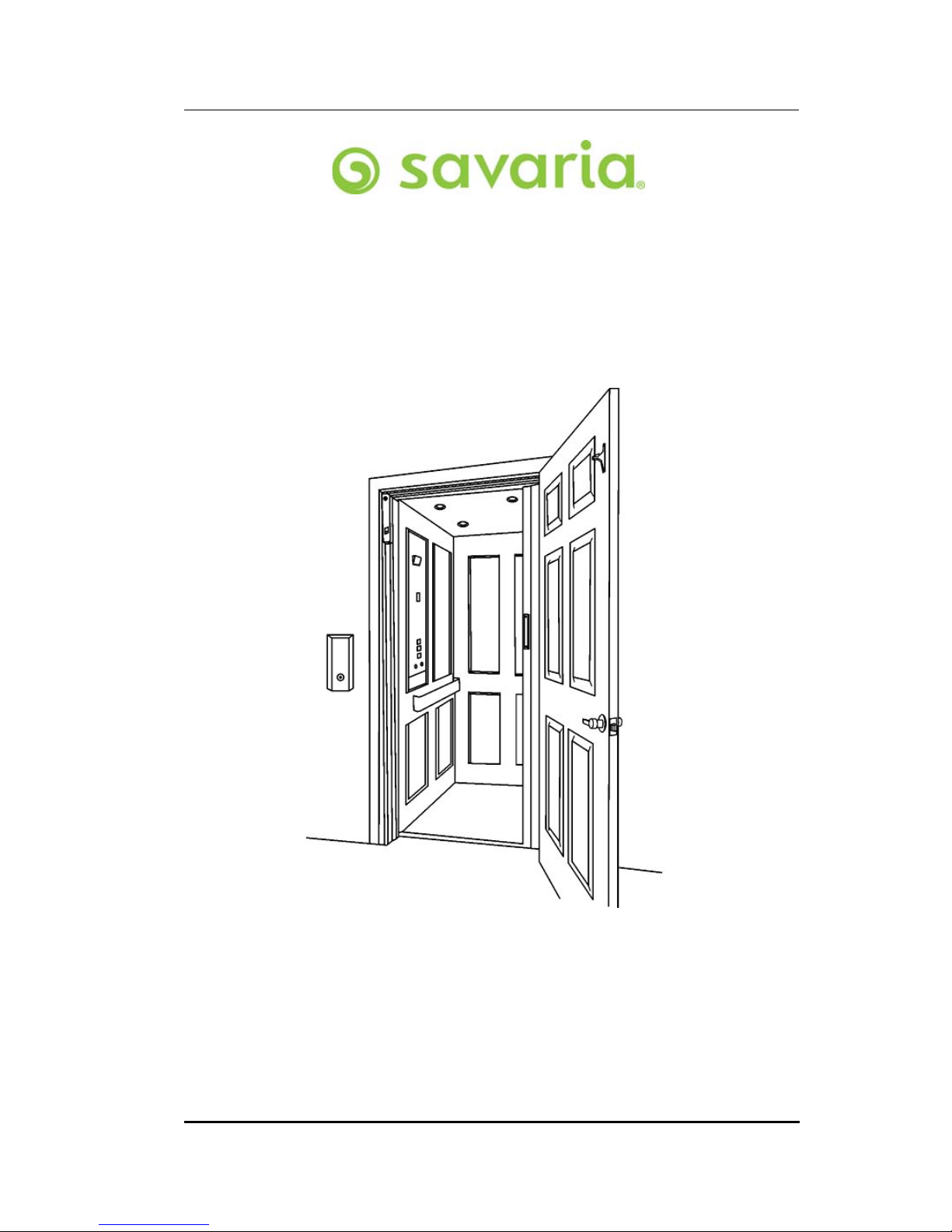
Eclipse
Residential Elevator
(with Micro-6 Controller)
OWNER’S MANUAL
(To Be Retained by Owner After Installation
by Authorized Savaria Dealer)
Part No. 000841
12-m01-2018
Page 2
2
IMPORTANT
Ensure that only an Authorized Savaria Dealer installs and services the Savaria™
Eclipse Residential Elevator. Under no circumstances is anyone other than a
dealer with Savaria training and authorization to install, adjust, service or
modify any mechanical or electrical device on this equipment. Failure to follow
this warning can result in safety system compromises or defeat; this can result
in serious injury or death. Savaria accepts no liability for property damage,
warranty claims or personal injury, including death, in this circumstance.
Passenger safety is the result of countless details in the equipment’s design,
manufacture, and installation. After installation, reliable operation and
continual safe operation requires regular service and inspection at least twice
per year, or more frequently where usage, environment, or local jurisdiction
requires. As the Owner, you are responsible for ensuring that regular service
and inspections occur in a timely manner.
Refer to this manual for specifications, operating instructions and maintenance
of the Eclipse Residential Elevator.
Upon completion of installation, the dealer must provide you with the
following information and ensure it is recorded in this manual. In addition,
either the dealer or you must keep any service and/or maintenance records in
the Maintenance Record section of this manual.
WARRANTY
Ensure your Authorized Savaria Dealer provides you with a copy of the
manufacturer’s limited parts warranty and documentation relating to any
Dealer labour warranty.
-------------------------------------------------------------------------------------------------
FOR OWNER’S RECORDS
Customer Name: _________________________________________
Installing Dealer: _________________________________________
Dealer’s Telephone Number: _______________________________
Date Installed: ___________________________________________
Serial/Job Number: _______________________________________
Eclipse (Micro-6) Owner’s Manual Part No. 000841, 12-m01-2018
Page 3

Table of Contents
TO ENSURE SAFE OPERATION . . . . . . . . . . . . . . . . . . . . . . . . . . . . . . . . . . . . . . . . . . . . . . 4
1. SPECIFICATIONS . . . . . . . . . . . . . . . . . . . . . . . . . . . . . . . . . . . . . . . . . . . . . . . . . . . . . . . .5
2. FEATURES . . . . . . . . . . . . . . . . . . . . . . . . . . . . . . . . . . . . . . . . . . . . . . . . . . . . . . . . . . . . . .6
3. OPTIONS . . . . . . . . . . . . . . . . . . . . . . . . . . . . . . . . . . . . . . . . . . . . . . . . . . . . . . . . . . . . . . .8
4. OPERATION . . . . . . . . . . . . . . . . . . . . . . . . . . . . . . . . . . . . . . . . . . . . . . . . . . . . . . . . . . . . .9
Operating from the Landing Controls . . . . . . . . . . . . . . . . . . . . . . . . . . . . .9
Operating from the Cab Operating Panel (COP) Controls . . . . . . . . . .10
Cab Lights . . . . . . . . . . . . . . . . . . . . . . . . . . . . . . . . . . . . . . . . . . . . . . . . . . . . . .10
5. POWER FAILURE AND EMERGENCY LOWERING . . . . . . . . . . . . . . . . . . . . . . . . . .11
6. EMERGENCY LIGHTING . . . . . . . . . . . . . . . . . . . . . . . . . . . . . . . . . . . . . . . . . . . . . . . .11
7. MANUAL LOWERING . . . . . . . . . . . . . . . . . . . . . . . . . . . . . . . . . . . . . . . . . . . . . . . . . . .12
8. DIAGNOSTICS . . . . . . . . . . . . . . . . . . . . . . . . . . . . . . . . . . . . . . . . . . . . . . . . . . . . . . . . .13
9. MAINTENANCE . . . . . . . . . . . . . . . . . . . . . . . . . . . . . . . . . . . . . . . . . . . . . . . . . . . . . . . .14
Maintenance Record . . . . . . . . . . . . . . . . . . . . . . . . . . . . . . . . . . . . . . . . . . . .15
3
Part No. 000841, 12-m01-2018 Eclipse (Micro-6) Owner’s Manual
Page 4

4
TO ENSURE SAFE OPERATION
To ensure safe operation of this equipment, pay careful attention to the
important notes below.
• Read this manual carefully before using the equipment.
• To prevent accidents, adhere strictly to the instructions and keep clear
of moving parts at all times.
• Follow instructions on all equipment labels at all times. Replace any
damaged labels immediately.
• Ensure that only qualified personnel perform maintenance and service
on the unit.
• When replacing parts, be sure that only genuine Savaria parts are used.
• This unit is intended for use by a mature person who understands its
proper operation as set out in this manual.
• Prior to operation, make sure that:
• All doors and gates are locked and secure.
• All areas in and around the lift are clear of any obstructions.
• All lights are functioning properly.
• Test your keys and emergency stop button every month.
Eclipse (Micro-6) Owner’s Manual Part No. 000841, 12-m01-2018
Page 5
1. SPECIFICATIONS
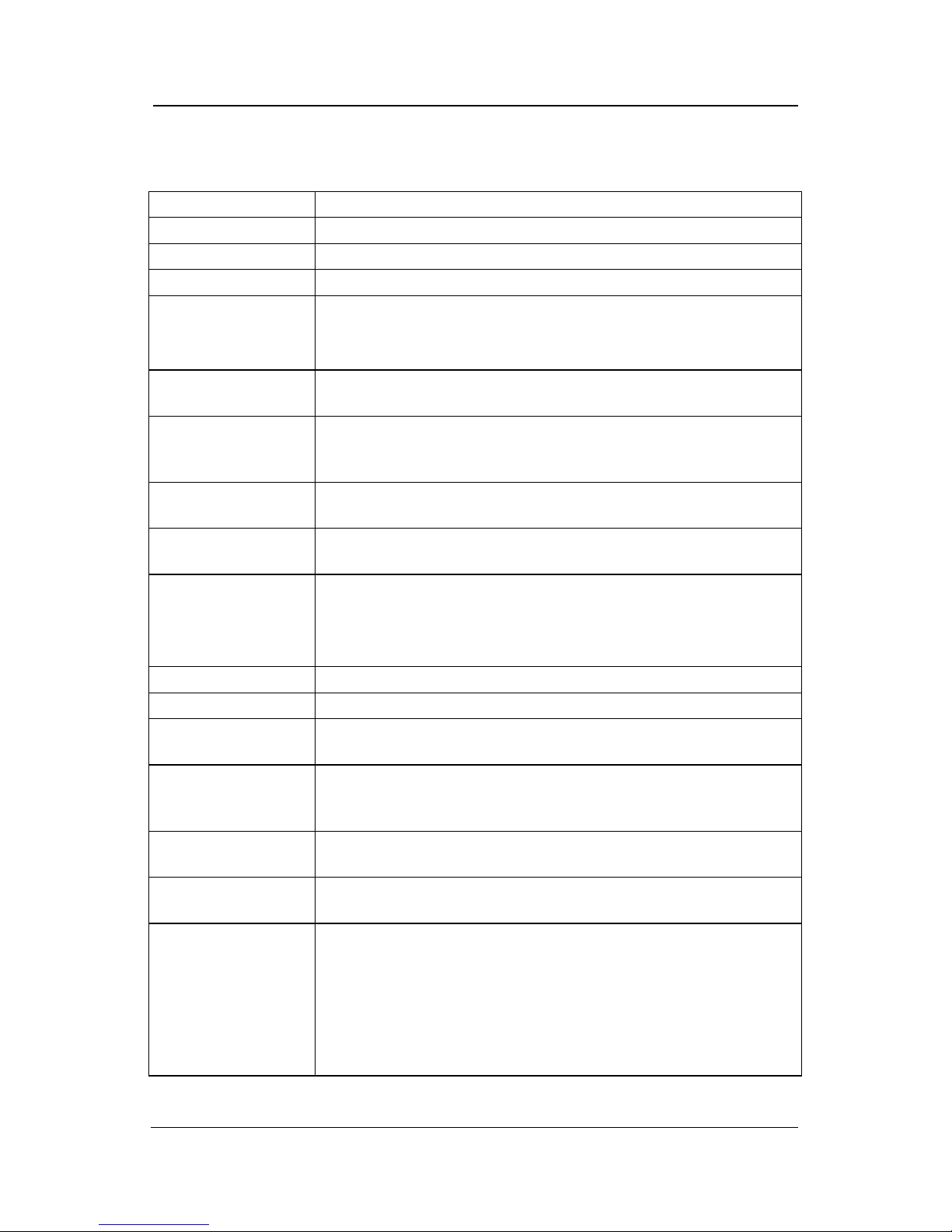
Eclipse Specifications
Load capacity 750 lb (341 kg), 950 lb (432 kg), 1000 lb (454 kg)
Rated speed 40 ft/min (0.2 m/s) nominal
Maximum travel 50 ft (15.24 m); 60 ft (18.3 m) available where code is not applicable
Maximum # of stops 6 stops
Normal: 40
Daily cycle
Power supply (circuit
supplied by others)
Lighting supply
(circuit supplied by
others)
Drive system
Operating
temperature
Cab sizes
Control system Micro-6 controller with diagnostics
Pit depth required 6” (152 mm); 11” (279 mm) minimum with buffer springs
Minimum overhead
clearance
Cab panel finish
Control panel finish
Hall station finish
Standard features
Heavy: 80
Excessive: 150
Maximum starts in 1 hour on standard installation: 20
North America: 230 volt, single phase, 60 Hz, 20 amps
International: 220 volt, single phase, 50 Hz
120 volt, 60 Hz, 15 amps
Automatic 2 HP geared motor roller chain variable frequency drive,
complete with counterweight
-10° C to +40° C (14° F to 104° F)
Types 1, 2, 3, 4 and 5:
• 36” x 48” x 80” (914 mm x 1219 mm x 2032 mm)
• 36” x 54” x 80” (914 mm x 1372 mm x 2032 mm)
• 36” x 60” x 80” (914 mm x 1524 mm x 2032 mm)
• 40” x 54” x 80” (1016 mm x 1372 mm x 2032 mm)
96” (2438 mm) for standard 80” cab, 114” (2896 mm) for 96” cab
Solid melamine or MDF panels (standard)
Unfinished veneer panels, finished recessed veneer panels, solid
hardwood raised panels (optional)
Clear or bronze anodized aluminum (standard)
Stainless steel or brass (optional)
Clear or bronze anodized aluminum (standard)
Stainless steel or brass (optional)
Automatic on/off cab lighting
Recessed gate pocket
Digital display in cab operating panel
Clear or bronze anodized aluminum cab entrance trim and handrail
Date plates, capacity tags
Modular rail sections
Unfinished plywood sub-floor
White ceiling with four LED lights
5
Part No. 000841, 12-m01-2018 Eclipse (Micro-6) Owner’s Manual
Page 6
6
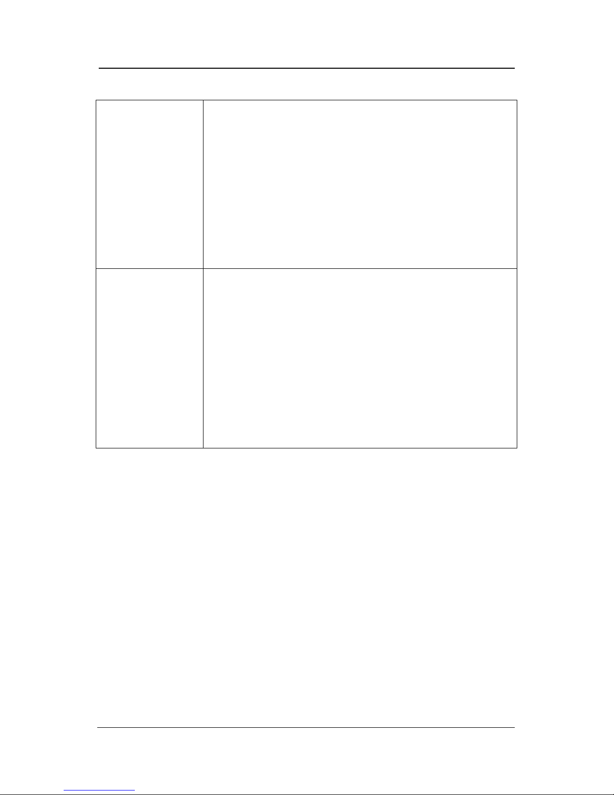
Eclipse Specifications (continued)
Cab gate safety switch
Main controller cab wall access safety switches
Pit run/stop switch and car run/stop switch
Emergency stop and alarm buttons
Uninterruptable power supply (UPS) battery back-up system for
lowering, automatic gate operation (if equipped) and electrical
Safety features
Options
interlock operation and lighting in the event of a power failure
Upper and lower limits
Motor access door (locked and switched)
Hand crank
Emergency lights
Final limit switch
Mechanical rail shoring blocks
Preset slack chain safety brake and switch
84” high cab, 96” high cab
Rated speed of 50 ft/min (0.25 m/s) available where code permits
Accordion car gate (choice of style)
Automatic gate operator (accordion gates only)
Buffer springs (11” pit depth minimum)
Laminate flooring in finished oak, maple, or cherry
Interlocks for doors by others
Keyed on/off hall stations
Oval hall call design
Cab interior in unfinished oak, birch, cherry, or maple veneer
Recessed cab panels in solid cherry, oak, or maple veneer
Raised cab panels in solid cherry, oak, or maple veneer
Telephone cabinet to match cab operating panel
Custom cab size
Ceiling panel to match walls
Eclipse (Micro-6) Owner’s Manual Part No. 000841, 12-m01-2018
Page 7
2. FEATURES
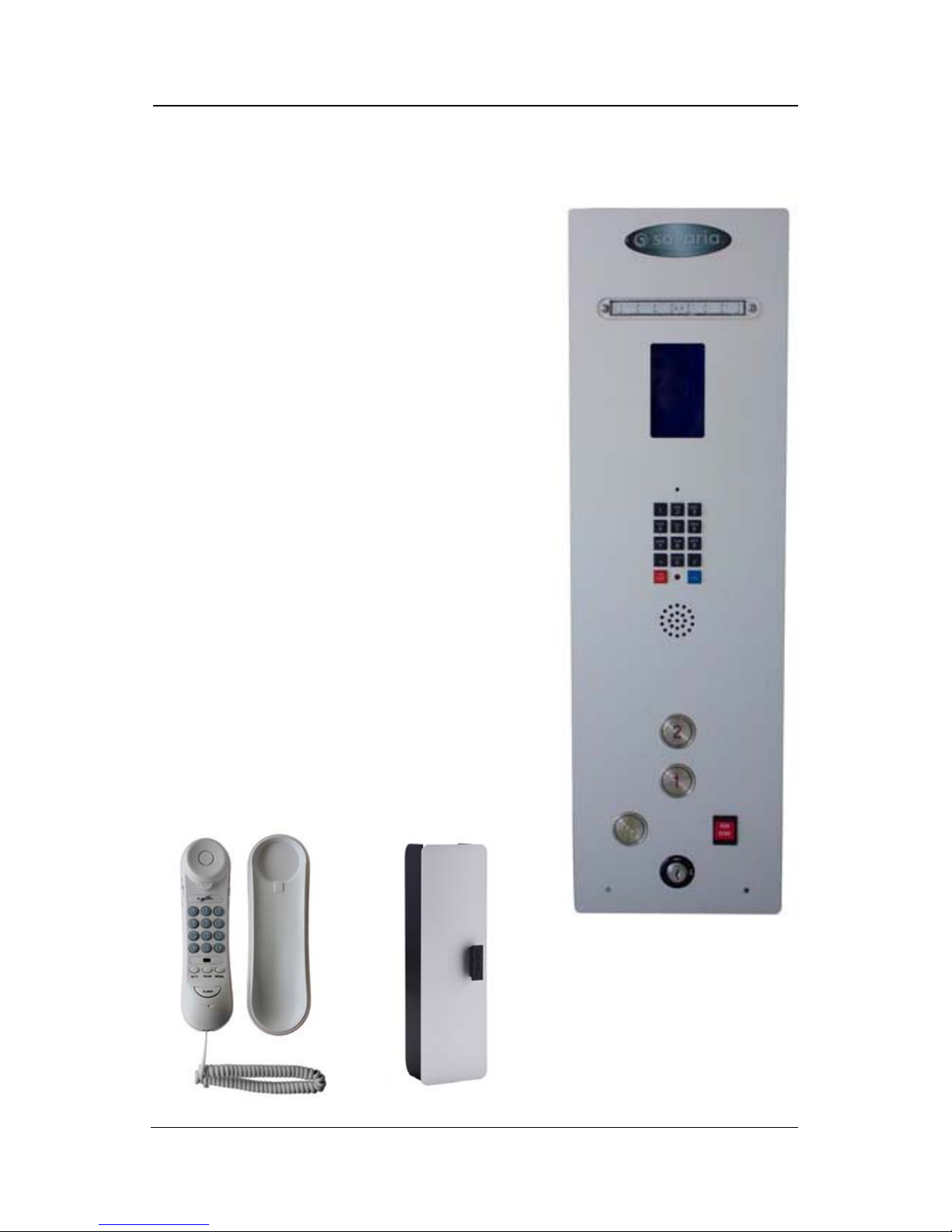
Figure 1: Sample COP
A
B
C
D
E
Figure 2: Standard Phone and Phone Box
1 Cab Key Switch (Figure 1-A)
The key switch turns the cab controls ON and
OFF. It is provided to limit the use of the
elevator to authorized persons only.
2 Cab Operating Panel Buttons (Figure 1-B)
Automatic control panel buttons facilitate the
UP/DOWN movement of the cab between
landings. Once the selected landing button is
pressed, the cab will automatically move to the
landing. The cab will stop when the selected
landing is reached.
7
3 Alarm Button (Figure 1-C)
This button can be pressed at any time to sound
the alarm in case of an emergency.
4 Run/Stop Button (Figure 1-D)
This button can be used at any time to stop the
cab and activate the alarm buzzer.
5 Keypad Phone (Figure 1-E)
For units that have a keypad phone, it will be on
the COP. For units that have a standard phone, it
will located in the phone box (see below).
Part No. 000841, 12-m01-2018 Eclipse (Micro-6) Owner’s Manual
Page 8
8
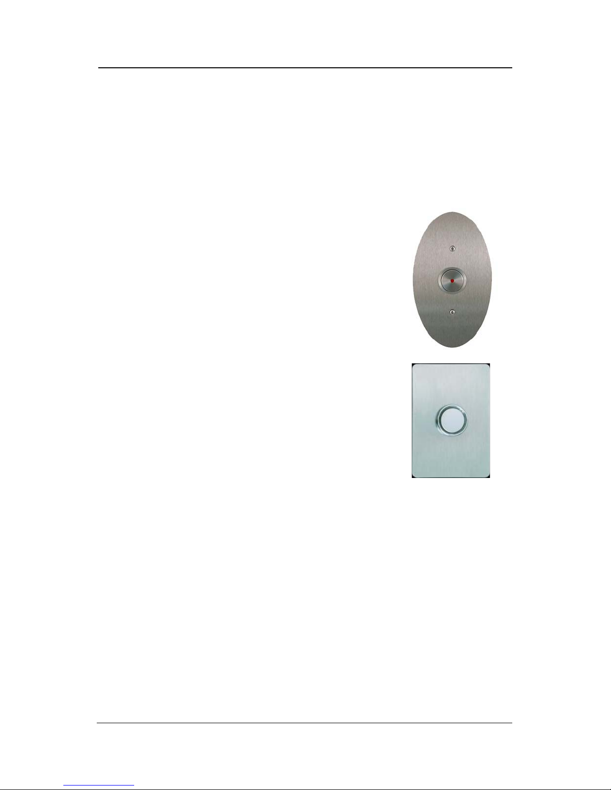
Figure 3: Hall Call
6 Handrail
A single handrail is mounted on the Cab Operating Panel side of the cab.
7 Emergency light
The cab emergency light remains ON in the event of a main power failure. The
emergency light uses a battery back-up system.
8 Landing Hall Call Station Controls (Figure 3)
Hall Call buttons are installed at all landings to move
the cab to the landing from which it is being called. An
optional key switch limits the use of the elevator to
authorized persons only.
9 Landing Door and/or Gate Interlock
The Landing Door/Gate lock prevents the movement of
the cab unless the door/gate is in the closed and locked
position. If the door/gate is not completely closed, the
cab will not move.
10 Emergency Battery Operation
In the event of a building power failure, the system is
provided with a temporary power back-up system to
allow the elevator to run down to the next available
landing, or to the first floor landing. On resuming
normal building power, the back-up system will turn
OFF and begin automatic recharging.
Eclipse (Micro-6) Owner’s Manual Part No. 000841, 12-m01-2018
Page 9
3. OPTIONS
NOTE
Automatic Door Opener
1 Press the Landing Hall Call button to call the elevator. The entrance door will
open automatically once the elevator stops at the landing.
2 Push N Go allows the entrance door to open automatically with a slight
push to the door itself. The door timer is inoperative when this feature is
activated.
Automatic Gate Opener
1 Press the Landing Hall Call button to call the elevator. If the entrance door is
equipped with an automatic door opener, it will open automatically once
the elevator stops at the landing; otherwise, open the entrance door
manually.
2 The gate will open automatically once the entrance door is fully open.
9
If the cab is equipped with a gate, the gate must be closed after
exiting the cab. If the gate is left open, all controls will remain
inoperable.
Part No. 000841, 12-m01-2018 Eclipse (Micro-6) Owner’s Manual
Page 10
10
NOTE
4. OPERATION
Operating from the Landing Controls
1 If equipped with a key switch, insert the key into the key switch on the Hall
Call station and turn the key to the ON position.
2 Press the Hall Call button once and release. The elevator will automatically
come to your landing.
3 Turn the key (if equipped) to the OFF position and remove the key.
4 If required, turn the door handle and pull the door open.
• Note that if you open the door and don’t open the gate (or interrupt
the light screen, if equipped), the unit will not take the next call and
will beep three times.
5 If the cab has a manual gate, slide the gate open and enter the cab.
6 Once inside the cab, close the gate, insert the key (if equipped) into the key
switch on the Cab Operating Panel, and turn the key to the ON position.
When using the landing controls, the cab can only be moved
(called) to the level from which you are calling. When using the
control buttons in the cab, the cab can be moved to any level.
WARNING
Wheelchair wheels must be locked at all times when the
elevator is moving.
Eclipse (Micro-6) Owner’s Manual Part No. 000841, 12-m01-2018
Page 11
11
NOTE
Operating from the Cab Operating Panel (COP) Controls
1 If equipped with a key switch, insert the key into the key switch on the Cab
Operating Panel and turn the key to the ON position.
2 Press the selected Landing button once and release. The elevator will
automatically travel to and stop at the selected landing.
3 Turn the key (if equipped) to the OFF position and remove the key.
4 Unlock the wheelchair wheels (if applicable) and exit the cab.
If the cab is equipped with a gate, the gate must be closed after
exiting the cab. If the gate is left open, all controls will remain
inoperable.
The outside landing door must be closed after exiting or entering
the cab. If the outside landing door is left open, all controls will
remain inoperable.
Cab Lights
If the cab door is left open and the cab lights turn off, there are two ways to get
the lights back on again:
• Enter the cab, close the door and gate and then press a Landing
button.
• Press a Hall Call button before entering the cab.
Part No. 000841, 12-m01-2018 Eclipse (Micro-6) Owner’s Manual
Page 12

12
NOTE
5. POWER FAILURE AND EMERGENCY LOWERING
In the event of a power failure, the elevator is equipped with a Battery Back-Up
system that allows you to lower the elevator from the inside of the cab. This
device operates on batteries and is only activated if a main power supply failure
occurs. The operation is as follows:
1 Press any Landing button below the floor where the elevator is located.
2 On arrival at the selected floor, the landing door will automatically unlock.
3 If there is an automatic gate, the gate will open.
4 Remove the key, open the manual gate (if equipped) and exit the cab.
6. EMERGENCY LIGHTING
In the event of a main power failure, the emergency COP light will turn on
automatically.
If one of the cab ceiling lights burns out, replace the bulb with a
10W bulb ONLY.
7. MANUAL LOWERING
In the event of a power failure, the UPS lowers the cab to the next landing and
opens the doors. Should the UPS fail, you can use the telephone to call for help.
The Manual Hand Crank can then be used to lower the elevator.
1 Instruct the passenger (s) in the elevator to remain calm and stay well back
from the door of the elevator. Ease their concern by telling them your
intentions.
2 Switch the main disconnect switch for the main power supply to the
elevator controller to the “OFF” position.
3 Locate the Motor Access Door, insert the Manual Hand Crank onto the
motor shaft and crank the elevator to the next lowest level.
4 To exit the cab, open the landing door (using the special emergency key)
and assist the passenger(s).
Eclipse (Micro-6) Owner’s Manual Part No. 000841, 12-m01-2018
Page 13
13
8. DIAGNOSTICS
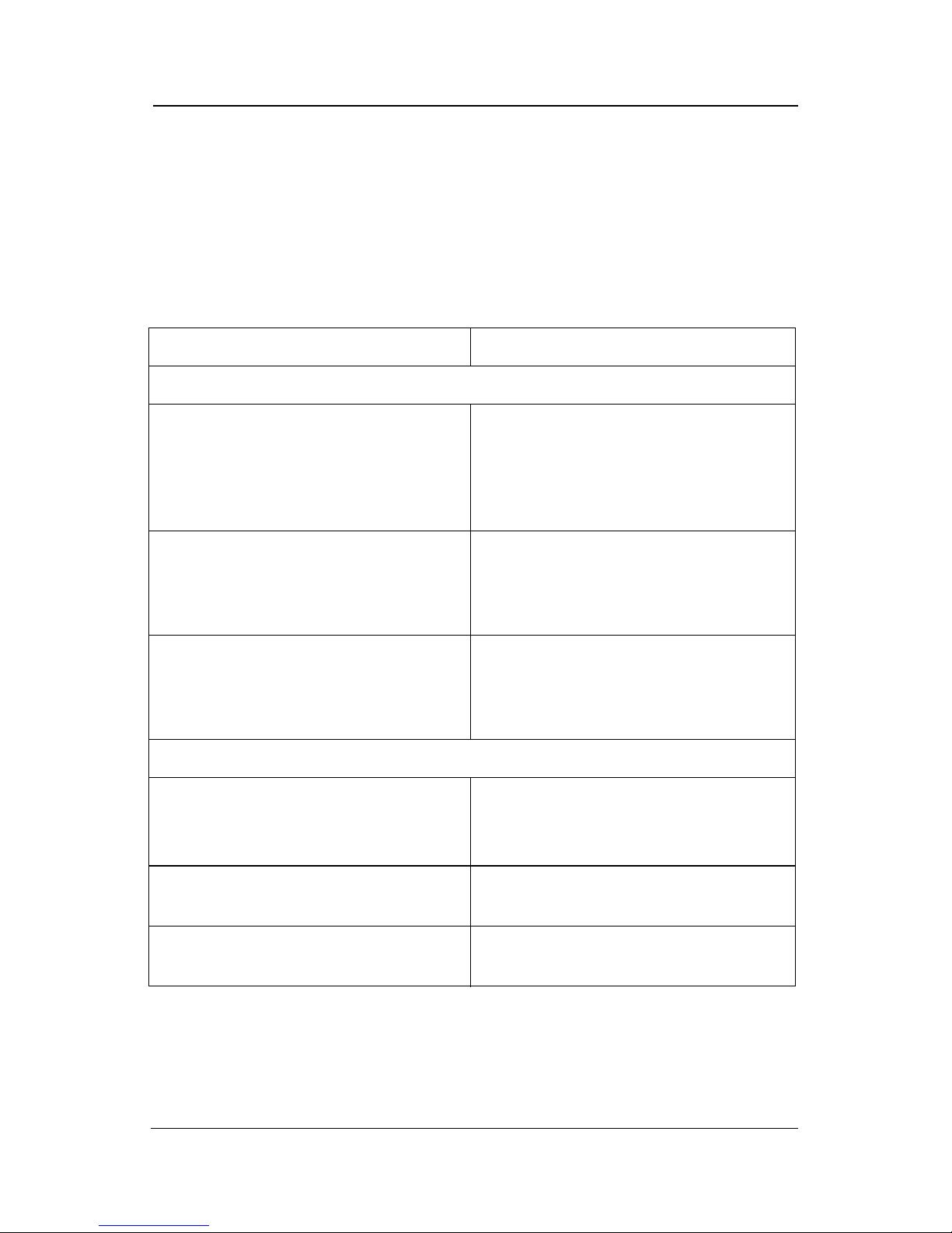
Diagnostic beep codes are provided on the Hall Calls to help you diagnose a
problem. All beep codes that begin with a long beep (on for 2 seconds) are
Service codes (contact your authorized Savaria dealer).
If you press a Hall Call button and it beeps but the car doesn’t move, refer to the
information in the following table.
Beep code Action to take
Service codes
1 long beep (2 seconds) followed by
1 short beep (1/2 second)
Contact your authorized Savaria dealer
for service. There is a problem in one of
the following areas: overload trip, run
timer trip, main safety chain open, door
lock fault, or auto shutdown counter.
1 long beep (2 seconds) followed by
2 short beeps (1/2 second)
1 long beep (2 seconds) followed by
3 short beeps (1/2 second)
User codes
1 short beep
(1/2 second)
2 short beeps
(1/2 second)
3 short beeps
(1/2 second)
Contact your authorized Savaria dealer
for service. There is a problem with
re-level shutdown or the low pressure
switch is activated.
Contact your authorized Savaria dealer
for service. There is a selector fault,
selector encoding error, or position
error.
Make sure the “Stop” switch in the car in
the Run position.
Check that the car gate is closed.
Check that the landing door is closed.
Manually open and close the gate.
Part No. 000841, 12-m01-2018 Eclipse (Micro-6) Owner’s Manual
Page 14
14
NOTE
NOTE
9. MAINTENANCE
Regular maintenance (performed by your Authorized Savaria Dealer) will keep
your elevator in proper operating condition. Please remember, as the owner of
this elevator, you are responsible for making sure that maintenance and
upkeep are done on a regularly scheduled basis.
If the unit is shut down for an extended period of time, contact
your Authorized Savaria Dealer to perform complete
maintenance before starting up the unit.
To ensure proper operating condition of your unit, the items listed below must
be inspected and, if necessary, serviced a minimum of twice per year.
Additional inspections may be required depending on usage.
1 Tighten all rail and cab fastening bolts.
2 Lubricate the door hinges and adjust the door closure if required.
3 Lubricate the rails with light grease, such as white lithium.
4 For a Gatemate operator, lubricate the shaft and bushing using a general
silicone lubrication spray (lubricate on installation as well).
5 Inspect the travelling cable for wear. Replace the cable if any cuts or damage
to the jacket are evident.
6 Replace the batteries inside the control panel as indicated on the battery
label.
7 Perform the required maintenance to the door locks.
8 Activate and test the safety mechanism.
9 Check, and if necessary, adjust the motor brake air gap. Refer to the Eclipse
Maintenance and Troubleshooting Guide (P/N 000858) to do this.
10 Check the “Replace Battery” light on the front of the UPS. If it is ON, replace
the battery inside the UPS. Otherwise, replace the UPS battery every 4 years.
11 Check that the phone is functioning properly.
Units installed in adverse environments will require additional
maintenance on a monthly basis.
Eclipse (Micro-6) Owner’s Manual Part No. 000841, 12-m01-2018
Page 15
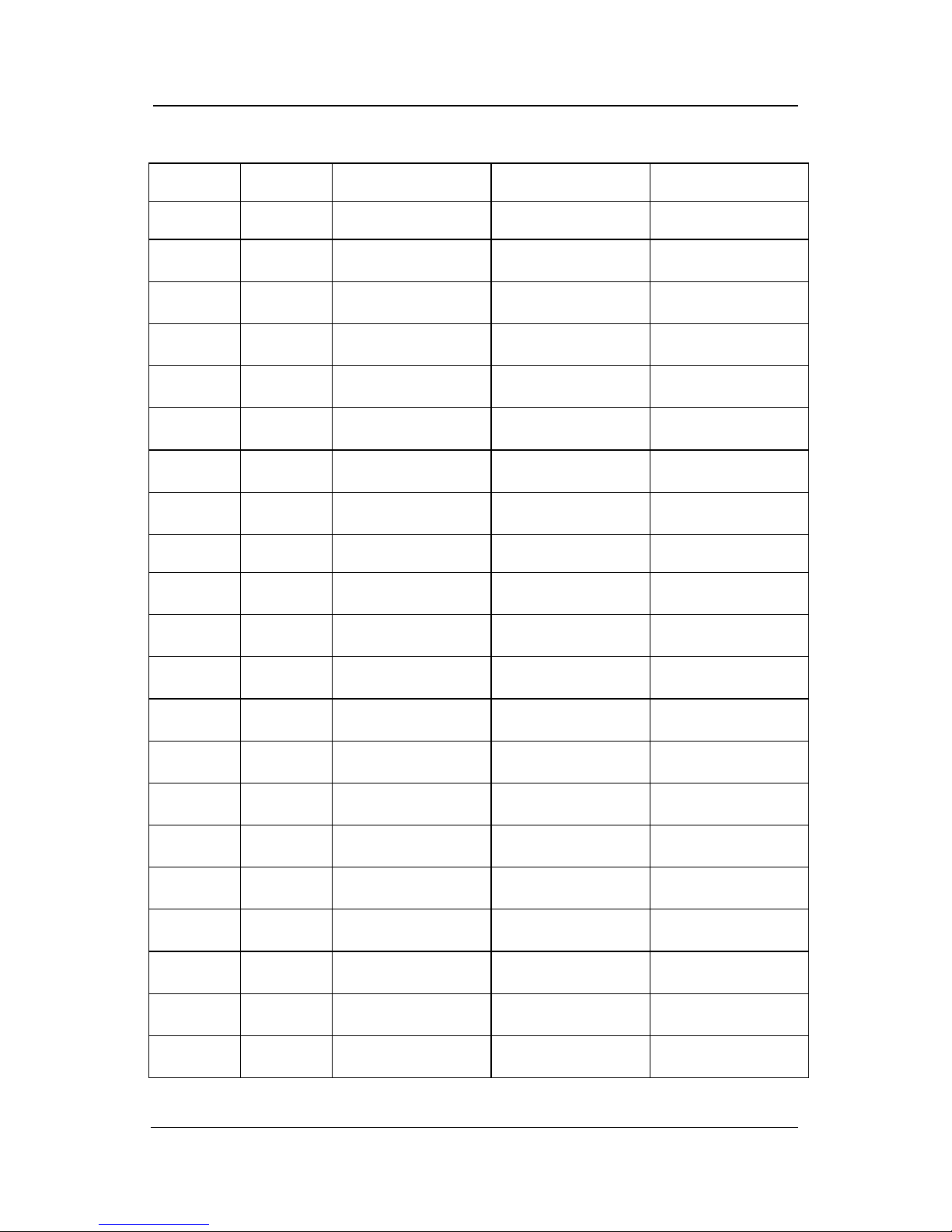
Maintenance Record
Date Time Reason for Call Comments Dealer
15
Part No. 000841, 12-m01-2018 Eclipse (Micro-6) Owner’s Manual
Page 16
Eclipse
Authorized Savaria Dealer
(with Micro-6 Controller)
OWNER’S MANUAL
Part No. 000841
Copyright 2018
Savaria Concord Lifts, Inc.
2 Walker Drive
Brampton, Ontario, L6T 5E1, Canada
www.savaria.com
For service or questions about this product, please contact your installing dealer.
DEALER NAME: _________________________________________________
DEALER PHONE: _________________________________________________
 Loading...