

The SmartControl 8 with PoE (SSC-P008) Quick Reference Guide provides information
Environmental
Temperature
32° to 104° F (0° to 40° C)
Humidity
10% to 90% Relative Humidity (non-condensing)
Cooling
1 cubic feet per minute (CFM) recommended
Maximum BTUs
17 BTUs per hour
Dimensions and Weight
Height
1.59 in/4.04 cm
Width
4.31 in/10.96 cm
Depth
6.50 in/16.51 cm
Weight
3.00 lb/1.36 kg (shipping weight)
PoE Power
PoE
RJ-45 10/100 Base-T, Power over Ethernet using the PoE
IEEE 802.3af standard.
Nominal Power
3 watts at 5V DC
Maximum Power
5 watts at 5V DC
Optional Power Supply
Input Power
5V DC, 120-240V AC, 50/60 Hz
1.3 watts at 5V DC
Nominal Power
1.6 watts at 120V AC
2 watts at 5V DC
Maximum Power
3 watts at 120V AC
Compliance
Safety and Emissions
FCC Part 15 | CE Mark | C-Tick
RoHS
Compliant
IR LED
Green indicates IR port signal activity.
Off indicates no IR port activity.
Ground Connector (Optional)
Connect this terminal to a suitable ground surface.
CPU Status LED
Green indicates the Host has established communications
with the SSC-P008.
Green flashing indicates the SSC-P008 is ready (running with
DHCP IP address), but the Host has not established
communications with the SSC-P008.
Off indicates the SSC-P008 is resetting or is booting the
embedded firmware.
Red indicates the Host has determined the firmware needs to
be updated, but a problem occurred during the process that
will initiate a reset.
Red flashing indicates the firmware is running, but has not
received a DHCP IP Address.
Amber indicates the Host is currently updating the firmware.
Amber flashing indicates the SSC-P008 has a valid link-local
IP Address and is waiting to connect to the Host.
1
6 7
2
3
4 5
8
1
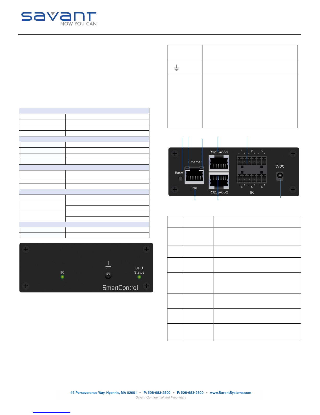
Reset button
Resets the factory default DHCP mode.
Press and hold the reset button for 5+ seconds.
2
Link LED
Green indicates an Ethernet link has been established.
Green flashing indicates Ethernet activity.
Off indicates an Ethernet link has not been established.
3
Activity LED
Green indicates an Ethernet speed of 100 Mb.
Off indicates an Ethernet speed of 10 Mb
4
RS232/485-1
8-pin RJ-45 female: Used to transmit and receive serial
binary data to and from devices. Supports RS-232/422.
5
IR (1-6 ports)
6-Pin Screw Down Plug in Connector: (5V tolerant only)
Sends IR signals to control devices with an IR input or IR
receiver via an IR flasher.
See IR Wiring for important precautions regarding IR
functionality before making any connections.
6
Ethernet
RJ-45 10/100 Base-T, auto-negotiating port.
Supports Power over Ethernet using the PoE IEEE
802.3af standard.
7
RS232/485-2
8-pin RJ-45 female: Used to transmit and receive serial
binary data to and from devices. Supports RS-232/422.
8
5V DC power
connector
(Optional)
5V DC input power to the SSC-P008.
SmartControl 8 (PoE)
(SSC-P008)
Quick Reference Guide
009-0807-03
SSC-P008-00
necessary to install the SSC-P008, a solution for small business installations or system
expansions. The SSC-P008 supports Power over Ethernet using the IEEE 802.3af standard.
Box Contents
(1) SmartControl 8 (SSC-P008)
(1) SSC-P008 Installation Kit (075-0124-xx)
(2) 6-Pin Screw-Down Connector (028-9352-xx)
•
(8) Screws #6 x 1/4 Phillips (039-0143-xx)
•
(2) Side mount brackets (071-0625-xx)
•
(1) Quick Reference Guide (this document)
Optional Accessories
Power Supply 5V DC 2.5 Amps (PWR-5025)
RS-232 Adapters (SAK-1000)
Infrared (IR) Emitters (IRB-1000)
Specifications
The next table describes the SSC-P008 LEDs
Front View of SSC-P008
Rear View of SSC-P008
The next table describes the functionality on the rear of an SSC-P008.
NOTE: All components requiring 120-240V AC, 50/60 Hz source power must be connected to a
surge-protected circuit.
140827

RS-232 Wiring
SmartControl 8 (PoE)
(SSC-P008)
Quick Reference Guide
009-0807-03
SSC-P008-00
RS-422 Wiring
RJ-45 to DB9 Adapters
Savant uses RJ-45 connectors for RS-232/422, other manufacturers devices may use the
standard DB9. To make connection easy, Savant offers RJ-45 to DB9 adapters in a variety of
configurations that can be used to connect to SmartControl for RS-232/422 control. Be sure and
choose the adapter that provides a proper connection to the control systems RS-232/422/485
port. Refer to the manufacturer’s support for the control systems configuration.
For more information on Savant RJ-45 to DB9 adapters, see RS-232 Conversion to DB9 and
RS-422/485 Pinout application note located on the Savant Portal.
IMPORTANT! If you are using RJ-45 to DB9 adapters not supplied by Savant:
Ensure that any wires required for communication/control are terminated within the
•
adapter.
Ensure that all wires NOT required for communication/control are NOT terminated in
•
the connecter.
Ensure that the unused wires in the connector are cut to prevent them shorting out, as
•
they are still terminated in the RJ-45 connector on the controller side.
IR Wiring
IR connections are made using 4-pin Screw Down Plug-in Connectors supplied with matrix or
receiver. The wire slips into the hole and locks screw located at the top of the connector
IMPORTANT! IR Wiring Precautions
Ensure that all IR emitters are within 15 feet (4.6 meters) from the chassis or receiver
•
location.
Use of 3rd party flashing IR emitters with Talk Back is not recommended. These types
•
of emitters can draw voltage away from the IR signal that can degrade IR
performance.
IR Connector Pinout
Network Requirements
Savant requires the use of business class/commercial grade network equipment throughout the
network to ensure the reliability of communication between devices. These higher quality
components also allow for more accurate troubleshooting when needed.
Connect all Savant devices to the same local area network (LAN) or subnet as the host. Savant
recommends not implementing any type of traffic or packet shaping in your network topology for
the Savant devices as this may interfere with performance.
Network Configuration
To ensure that the IP address of the SSC-P008 will not change due to a power outage, a static
IP address or DHCP reservation should be configured. Savant recommends using DHCP
reservation within the router. By using this method, static IPs for all devices can be managed
from a single UI avoiding the need to access devices individually.
DHCP Reservation
Setting DHCP reservation varies from router to router. Refer to the documentation for the router
on how to configure DHCP reservation.
Network Changes Require Rebooting the SSC-P008
The SSC-P008 requires rebooting after connecting to a new network, changing routers, or if the
IP address range is changed in the current router. If the SSC-P008 is not rebooted after making
network changes, the controller will not sense the changes made to the network or IP settings.
The Status LED will start to flash and reports will be logged within System Monitor.
Restoring System Defaults
To restore the default state of the SSC-0008, do the following.
1. Press and hold the reset button for 5+ seconds.
2. The CPU Status LED will blink green briefly while the firmware clears the static IP address.
3. The system will then reboot and come back with the CPU Status LED flashing green, if the
system received an IP address from the DHCP server. If the system has a self-assigned,
local IP address, the LED will be flashing amber. See the Front panel, CPU Status LED,
amber flashing description above.
SSC-P008 Mounting Bracket Installation
Use the supplied screws to install the mounting brackets (071-0625-xx) to the SSC-P008 in the
example shown below.
Additional Documentation
Additional Documentation is available on the Savant Portal
Knowledge Base > Savant Hardware > SmartSystem Controllers > SmartControl (Control
Only)
Copyright © 2014 Savant Systems, LLC. SAVANT and RacePoint Blueprint are trademarks of Savant Systems, LLC.
All brand names, product names and trademarks are the property of their respective owners.
Savant Systems, LLC reserves the right to change product specifications without notice.
140827
 Loading...