

Page 1
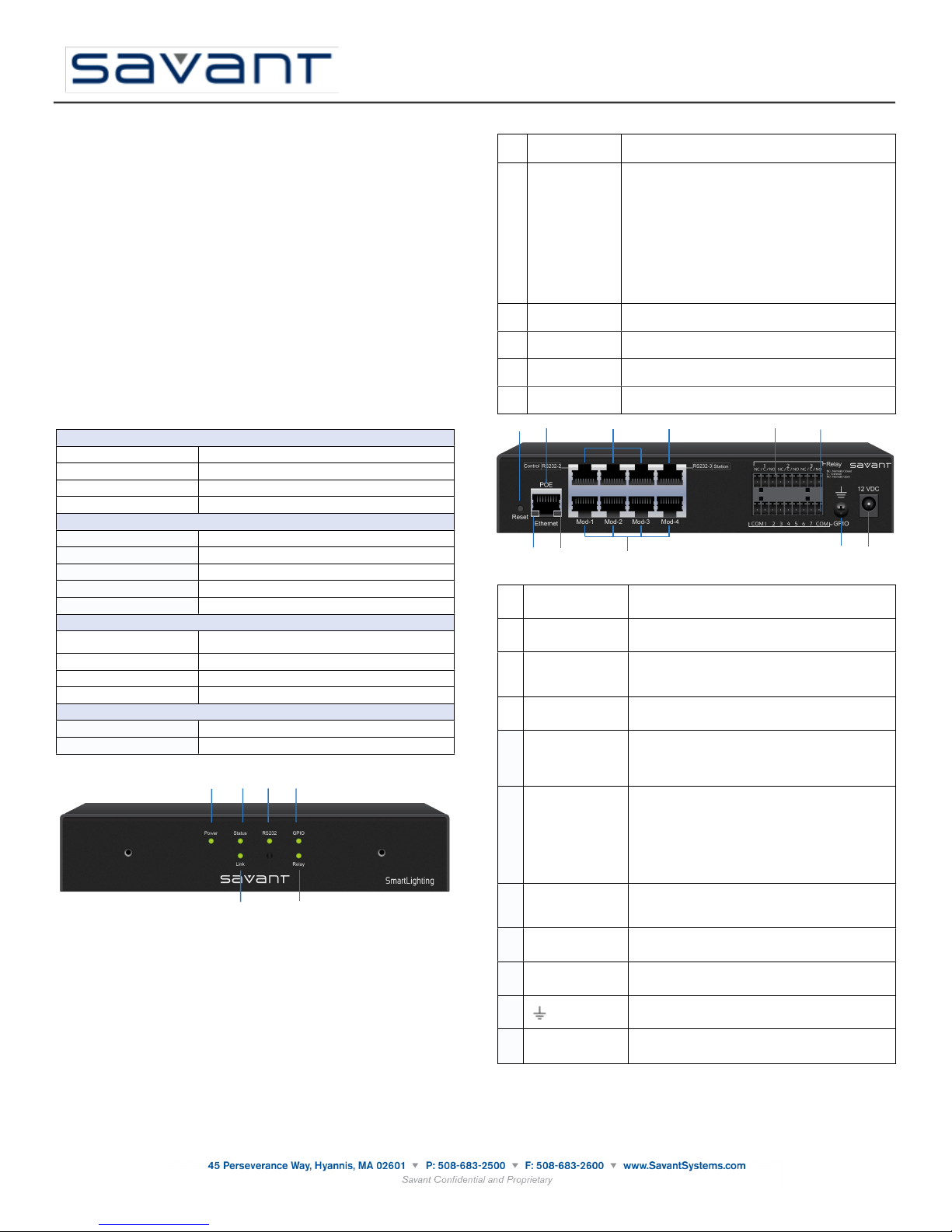
The Savant® SmartLighting 18 with PoE (SSL-P018) Quick Reference Guide provides all the
Environmental
Temperature
32° to 104° F (0° to 40° C)
Humidity
10% to 80% Relative Humidity (non-condensing)
Cooling
2 cubic feet per minute (CFM) recommended.
Maximum BTUs
41 BTU/hour
Dimensions and Weight
Height
1.52 in/3.86 cm
Width
7.99 in/20.29 cm
Depth
7.60 in/19.30 cm
Weight
6 lb/2.72 kg
Rack Space
1U
Power
PoE
RJ-45 10/100/1000 Base-T, Power over Ethernet using the
PoE IEEE 802.3af standard
Nominal Power
7 watts
Maximum Power
12 watts
Optional Power Supply
12V DC, 120-240V AC, 50/60 Hz
Compliance
Safety and Emissions
FCC Part 15 | CE Mark | C-Tick
RoHS
Compliant
3
5
1
6
42
1
Power LED
GREEN indicates the system has adequate power and is
operating normally.
OFF indicates that the system is getting no power.
2
Status LED
GREEN indicates the system is operating normally.
GREEN flashing indicates the embedded system is ready
(running with DHCP IP address), but the Host has not
established communications with the embedded system.
OFF indicates the embedded processor is resetting or is booting
the embedded firmware.
RED indicates the Host has determined the firmware needs to
be updated, but a problem occurred during the process that will
initiate a reset.
RED flashing indicates the embedded firmware is running, but
has not received a DHCP IP Address.
AMBER indicates the Host is currently updating the embedded
firmware.
AMBER flashing indicates the embedded system has a valid
link-local IP Address and is waiting to connect to the Host.
3
RS-232 LED
GREEN indicates RS-232/422/485 serial port data activity.
OFF indicates no RS-232/422/485 serial port activity.
4
GPIO LED
GREEN indicates GPIO port signal activity.
OFF indicates no GPIO port activity.
5
Link LED
GREEN indicates Ethernet Link port signal activity.
OFF indicates no Ethernet Link port activity.
6
Relay LED
GREEN indicates Relay port signal activity.
OFF indicates no Relay port activity.
1 2 3 4
8765
1 2 3 4 5
7
6
8
10911
1
Reset Button
Resets to factory default DHCP mode.
Press and hold the reset button for 5+ seconds.
2
PoE/Ethernet
RJ-45 10/100/1000 Base-T, auto negotiating port.
Supports Power over Ethernet using PoE IEEE 802.3af
standard.
3
RS-232
Control
(RJ-45)
Port 1 - used to control lighting from a Savant System
Ports 2 - 3 - Spare RS-232/RS-422 data ports
4
Station
Port 4 - defaults to RS-422 for communication with SKL-1000
and SKL-4000.
5
Relay 1-3 NC/C/NO
(Normally Closed/
Common/Normally
Open)
These ports provide dry contacts (open/closed) to control
devices requiring basic on/off operation. A single relay port can
carry a maximum of 30V DC with a maximum current of 1
amp. Input from a device to the Savant controller is not
supported through a relay.
6
GPIO COM, 1 – 7,
COM
General Purpose Input Output ports use 9-pin screw-down
connectors (3.81 mm).
The digital GPIO ports are binary I/O ports used for input.
Each GPIO is individually configured as an input trigger. All
seven GPIO pins use the COM pins for common ground (at
each end of the GPIO block).
The GPIO port detects a voltage present (GPIO input). GPIO
inputs can safely detect the presence of a voltage of 0-30V DC
with a threshold of 2.4V DC.
7
Ethernet
Link/Activity LED
GREEN indicates an Ethernet link has been established.
GREEN flashing indicates Ethernet activity.
OFF indicates an Ethernet link has not been established.
8
Ethernet Speed LED
GREEN indicates an Ethernet speed of 100 Mb.
OFF indicates an Ethernet speed of 10 Mb.
9
Mod-1—Mod-4
Default to RS-422 and used to communicate with
SmartLighting modules.
10
Ground Connector - used to connect to a suitable ground
reference when using Power over Ethernet.
11
12 VDC
Provides optional 12V DC input power when PoE is not
available.
Savant SmartLighting 18
(SSL-P018)
Quick Reference Guide
009-0667-00
SSL-P018-00
steps necessary to operate the SSL-P018. The SSL-P018 supports up to 256 keypads with up to
8 SKL-4000s. The SSL-P018 supports Power over Ethernet (PoE) using the PoE IEEE 802.3af
standard.
Box Contents
(1) SSL-P018
(1) Installation Kit (075-0135-xx)
(2) 9-Pin Screw-down Connector (028-9353-xx)
•
(4) Flat Phillips Screw - M3x8mm (039-0017-xx
•
(2) Side mount brackets - pair (071-0628-xx))
•
(1) Quick Reference Guide (this document)
Required System Component
Savant Keypad Link
•
SKL-1000
•
SKL-4000
Savant Modules
Savant Keypads
Station Bus Cabling
•
100 ft/30.48 meters (CBL-4100)
•
250 ft/76.20 meters (CBL-4250)
•
500 ft/152.40 meters (CBL-4500)
•
1000 ft/304.8 meters (CBL-41000)
Optional Accessories
(1) Power Supply 12V 15W 1.25A with 5.5mm connector (PWR-12125-xx)
(1) Rack Mount Brackets (RMB-0025)
Specifications
Front View of SSL-P018
Rear View of SSL-P018
Note: The SSL-P018 Station port defaults to RS-422 but is configurable to RS-232 by Dealer .
1010112
Page 2
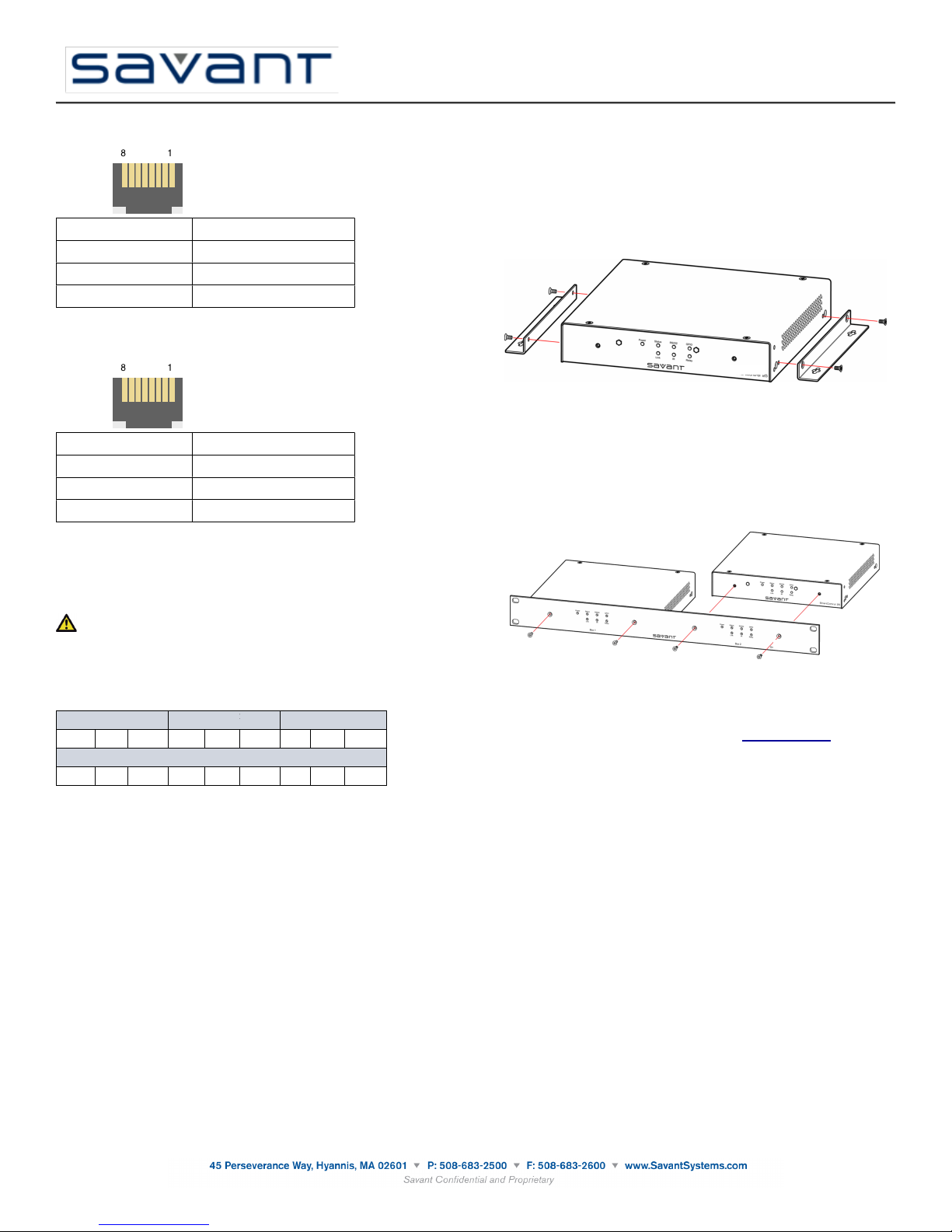
RS-422/RS-485 Pinouts
1 (RS+ (RS-422/485)
5 (Not used for RS-422/485)
2 RS- (RS-422/485)
6 TX- (RS-422/485)
3 TX+ (RS-422/485)
7 (Not used for RS-422/485)
4 GND (RS-422/485)
8 (Not used for RS-422/485)
1 (Not Used for RS-232)
5 RXD (RS-232)
2 (Not Used for RS-232)
6 TXD (RS-232)
3 (Not Used for RS-232)
7 CTS (RS-232) ports 1 and 2 only
4 GND (RS-232)
8 RTS (RS-232) ports 1 and 2 only
Relay 1
Relay 1
Relay 2
Relay 2
Relay 3
Relay 3NCCNONCCNONCC
NO
GPIO
GPIO
GPIO
GPIO
GPIO
COM1234567COM
Savant SmartLighting 18
(SSL-P018)
Quick Reference Guide
009-0667-00
SSL-P018-00
Controller RJ-45 (RS-422/RS-485) Plug Pinouts
RS-232 Wiring
When using SSL-P018 Station Ports 1, 2 and 3.
Controller RJ-45 (RS-232) Plug Pinouts
SSL-P018 provides Control and RS-232-2 Ports (RTS/CTS) can be used to implement flow
control. Flow control manages data transmission between two devices. For example, the SSLP018 may transmit data at a faster rate than the other device can receive and process the data.
Using the RS-232 protocol control lines RTS (Request To Send) and CTS (Clear To Send) to
implement flow control, the SSL-P018 sends Request to Send frame (RTS) to the other device.
If the device answers with a Clear To Send frame (CTS), the SSL-P018 sends the data. After a
successful exchange, the device replies with an acknowledgement frame (ACK).
Mounting Installation
The SSL-P018 can be placed on a 1U rack shelf, wall mounted using the side-mounting
brackets (included) or rack mounted using RMB-0025 brackets (optional).
Wall Mounting
Side mounting brackets are shipped with the SSL-P018.
Use the supplied screws to install the brackets to the SSL-P018 as shown.
Side-mounted brackets are used to install the SSL-P018 on the wall.
Optional Rack Mounting Bracket (RMB-0025)
Use the supplied screws to install the faceplate to the SSL-P018 as shown.
Important
If you are using RJ-45 to DB-9 adapters not supplied by Savant, be sure to terminate any wires
required for communication/control within the adaptor. Ensure that all wires required for
communication/control are not terminated in the connector. Also, ensure that the unused wires in
the connector are cut to prevent them shorting out, as they are still terminated in the RJ-45
connector on the controller side.
Relay and GPIO Port Pinouts (9-pin 3.81mm screw-down connectors)
Interconnect the Network
The SSL-P018 requires business class/commercial grade network equipment in order to handle
the IP traffic between Savant SmartSystems™ and Savant SmartLighting network equipment.
When configuring the network ensure that all of the connected Savant units (including SSL-P018
and HST-4001) are on the same local area network (subnet or LAN). When on the same
network, Savant units locate each other using the Bonjour® network protocol.
Network Changes Require Rebooting SSL-P018
The embedded processor used in the SSL-P018 controller, needs to be rebooted after switching
to a new network with a new IP address range. If you do not reboot, the controller will not
recognize the network and IP address changes. The Status LED on the front panel of the
controller will start to flash.
Rack-mounted brackets are used to install the SSL-P018 in a rack.
Additional Documentation
Additional Documentation for the SSL-P018 is available at: savantsystems.com
Products >
Savant Lighting Control
•
Copyright © 2012 Savant Systems, LLC. SAVANT and RacePoint Blueprint are trademarks of Savant Systems, LLC.
All brand names, product names and trademarks are the property of their respective owners.
Savant Systems, LLC reserves the right to change product specifications without notice.
1010112
 Loading...