

Page 1
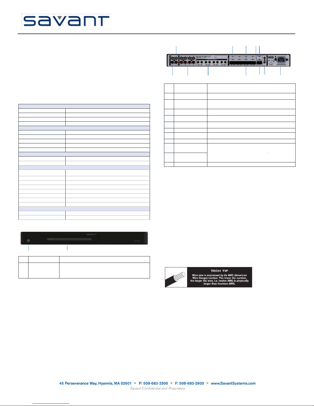
The Savant Multi-Room AMP (AMP-8125) Quick Reference Guide provides all the steps
Environmental
Temperature
32° to 95° F (0° to 35° C)
Humidity
10% to 80% Relative Humidity (non-condensing)
Cooling
34 cubic feet per minute (CFM) recommended.
BTUs
650 BTUs per hour
Dimensions and Weight
Height
1.70 in/4.50 cm
Width
17.30 in/43.94 cm
Depth
14.9 in/37.88 cm
Weight
9.2 lb/4.2 kg
Rack Space
1U
Power
Input Power
100-240V AC, 50/60 Hz
Nominal Power
190 watts
Operating Parameters
Output Power
125W RMS/channel@8 ohms from 20Hz - 20kHz (all
channels driven)
Frequency Response
20Hz - 20kHz +0dB/-1.5dB
Total Harmonic Distortion (THD)
<0.05% - 20Hz - 20KHz (At Full Rated Power)
Signal-to-Noise Ratio (SNR)
>105dB ref: full power (a-weighted)
Crosstalk
< -70dB @ 1kHz
Input Sensitivity
1.12 volts for 125 watts out in 8 ohms
Gain
29dB
Input Impedance
100K ohms (typical)
Compliance
Safety and Emissions
FCC Part 15 | CE | CAN/CSA | C-Tick
RoHS
Compliant
1
2
1
Standby Button
Red indicates that the unit is in standby mode.
Blue indicates that the system is powered on.
2
Channel Status LEDs
(1-8)
Blue indicates the channel has adequate power and is
operating normally.
Blue flashing indicates the channel has a fault such as a short
or some other problem.
Off indicates that the system is in standby mode.
1
2
3 4
5
6
7
8 9
10
11 12
1
Bus Output
Provides RCA connector loop/pass-thru output for connecting
multiple AMP-8125s in a system utilizing a single bus input
signal.
2
Bus Input
Provides RCA connectors input to simultaneously feed all
speaker output channels utilizing a single bus input signal.
3
Local Inputs
Provides eight RCA input connectors input to feed a
corresponding speaker-level output channels labeled in pairs
A, B, C and D. .
4
Output Level Controls
Provides eight Stereo line-level audio outputs labeled in pairs
A, B, C and D.
5
Stereo Mono
Selection
Selects between stereo and mono output configuration for
each group of speaker output pairs.
6
Local/Bus Selection
Selects between local and bus inputs for each group of
speaker output pairs.
7
Speaker Outputs
Provides connection for up to four pair of stereo speakers.
8
Signal Sense On/Off
Enables the audio Signal Sense circuitry for the bus and local
inputs.
9
Power Save On/Off
Enables the extreme low-power automatic standby mode.
10
Trigger In/Out
connector
(Phoenix-style)
Provides connectivity for remote 5-15V DC trigger signals
used to activate and deactivate the standby mode from
11
Trigger In/Out
connector
(Mono mini- plug)
Provides connectivity for remote 5-15V DC trigger signals
used to activate and deactivate the standby mode from
devices.
12
Input Power
100-240V AC, 50/60 Hz
Savant Multi-Room AMP
(AMP-8125)
Quick Reference Guide
009-0631-02
AMP-8125-00
necessary to set up the AMP-8125.
Box Contents
(1) AMP-8125
(1) Installation Kit (075-0142-xx)
(2) 1U Rack Mounting Brackets (071-0715-xx)
•
(4) Screws for Rack Mounts (039-0236-xx)
•
(6) Torx Screws for Brackets (039-0237-xx)
•
(1) Torx Wrench (071-0755-xx)
•
(4) Plastic Feet (074-0445-xx)
•
(4) Phillips Screws for Plastic Feet (039-0238-xx)
•
(4) 4-position Phoenix-style Connectors for audio output (028-0454-xx)
•
(1) 3-position Phoenix-style Connector for Trigger I/O (028-0455-xx)
•
(1) Power cord (3 feet) (N. America) (064-0333-xx) or appropriate international power cord
•
(1) Quick Reference Guide (this document)
Required System Component
(1) Any Savant Controller with RCA Audio Output connectors
Specifications
Note: The Power Save function can only be used when operating the AMP-8125 from the front
panel standby button. If a trigger input is being used, it will override the Power Save function.
Installation Considerations
The AMP-8125 should be installed on a solid, flat, level surface such as a table or shelf using the
four plastic feet that are shipped with the product.The AMP-8125 can also be installed in a
standard 19-inch equipment rack using the rack-mount brackets included with the product.
Select a dry, well ventilated location out of direct sunlight.
If multiple AMP-8125s are rack mounted together, it is acceptable to “flat stack” them one atop
the other in adjacent rack spaces without additional ventilation spaces left in between them.
However, in some installations or in heavy usage scenarios where multiple channels are
consistently driven at high outputs for long periods of time, it might be necessary to leave one
empty rack between the amplifiers in order to assist with heat dissipation and prevent thermal
protection due to overheating.
Cable and Wire
The AMP-8125 has multiple connections on the back panel. Savant recommends that the input
cables and the speaker wires are clearly labeled. Label the cables and the wires with their
destination or source, not the AMP-8125 terminal. Modifications will be easier in the future.
The AMP-8125 connects to your Savant multi-room audio solution via shielded line level audio
cables with RCA Audio Output connectors. Use high quality RCA cables to connect the multiroom audio to the amplifier inputs.
The AMP-8125 connects to your speakers using 2-conductor speaker wire. For most
applications, Savant recommends using 16 or 18 gauge wire. For wiring runs longer than 80 feet
Savant recommends using 14-gauge wire. Each channel features a removable screw terminal
speaker connection for easy installation in tight spaces. The terminal connector can
accommodate up to 14-gauge stranded speaker wire.
Copyright © 2012 Savant Systems, LLC. SAVANT and RacePoint Blueprint are trademarks of Savant Systems, LLC.
All brand names, product names and trademarks are the property of their respective owners.
Savant Systems, LLC reserves the right to change product specifications without notice.
091812
Page 2
Speaker Wire Connections
!!"#0OWER!MPLIlERS
1. Read the se instructions.
2. Keep these instructi ons.
3. Heed all warn ings.
4. Follow all instruc tions.
5. Do not use this appa ratus near water.
6. Clean only with a dr y cloth.
7. Do not block any ventilation openings. Install in accordance with
the manufacturer’s instr uctions.
8. Do not ins tall near any heat sources s uch as radiators, heat
registers, stoves, or other ap paratus (includin g ampliers) that
produce heat.
9. Do not defeat the safet y purpose of the polarized or groundin gtype plug. A po larized plug has two bla des with one wider than
the o ther. A grounding-ty pe plug has two blades and a third
grounding prong. The wide bl ade or the third prong is provided
for your safety. If the provide d plug does not t into your outlet,
consult an electrician for re placement of the obsolete outlet .
10. Prote ct the p ower cord f rom being walked on or pinche d,
particularly at plugs, conveni ence receptacles, and the point
where they exit from the app aratus.
11. Onl y use attachments/accessories specied by the manufacturer.
12. Use only with a cart, stand, trip od, bracket, or table
specied by the manufacturer, or sold with the apparatus.
When a cart is used, use caution when moving the cart/
apparatus combination to avoid injury from tip-over.
13. Unplug this apparatus du ring lightning storms o r when unused
for long periods of time.
14. Refer all servicing to qualied service per sonnel. Servicing is
required when the apparatus has be en damag ed in any way,
such as power-supply cord or plug is damaged, liquid has been
spilled or objects have fallen into th e apparatus, th e apparatus
has been exposed to rain or moisture, does not operate normally,
or has been dropped.
15. Use the mains p lug to disconnect the apparatus from the mains.
16. WA RNING : TO RED UCE THE RISK OF FIRE OR ELECTRIC S HOCK,
DO NOT EXPOSE THIS APPARATUS TO RAIN OR MOISTURE .
17. DO NOT EXPOSE THIS EQU IPMENT TO DRIPPING OR
SPLASHING AND ENSURE THAT NO OBJECTS FILLED
WITH LIQUIDS, SUCH AS VASES, ARE PLACED ON T HE
EQUIPMENT.
18. THE MAINS PLUG OF THE POWER SUPPLY CORD SHALL REMAIN
READILY OPERABLE.
TO PREVENT ELECTRIC SHOCK DO NOT REMOVE TOP OR
BOTTOM COVERS. NO USER SERVICE ABLE PARTS INSIDE.
REFER SERVICING TO QUALIFIED SERVICE PERSONNEL .
TO COMPLETELY D ISCONNECT THIS EQUIPMENT FROM THE
AC MAINS, DISCONNECT TH E POWER SUPPLY CORD PLUG
FROM THE AC RECEPTACLE. THE MAINS PLUG OF TH E
POWER SUPPLY CORD SHALL REMAIN READILY OPERABLE.
WATCH FOR THESE SYMBOLS:
The lightning bo lt triangle is used to alert the u ser to the
risk of electric shock .
The exclamation point triangle is used to alert the user to
important operatin g or maintenance instructions.
IMPORTANT
DD-8 ampliers re quire Class 2 output wiring.
MAGNETIC FIELD
CAUTION! Do not locate sensitive high- gain equipment such as
preampliers or tape decks directly above or below the unit. Because
this amplier has a high power density, it has a strong magnetic eld
which can induce hum into unshielded devices th at are located
nearby. The eld is strongest jus t above and below the unit.
If an equipment rack is used, we recommend locating the amplier(s) in
the bottom of the rack and the preamp lier or oth er sensitive
equipment at the top.
!!"#0OWER!MPLIlERS
!""#"$%&'()*"+#*$,("+
This device complies with part 15 of the FCC rules. Operation is subject to the
following two conditions: (1) This device may not cause harmful interference, and (2)
this device must accept any interference received, including interference that may
cause undesired operation.
CAUTION: Changes or modications not expressly approved by the party
responsible for compliance could void the user’s authority to operate the equipment.
NOTE: This equipment has been tested and found to comply with the limits for a
Class B digital device, pursuant to part 15 of the FCC Rules. These limits are designed
to provide reasonable protection against harmful interference in a residential
installation. This equipment generates, uses, and can radiate radio frequency energy
and, if not installed and used in accordance with the instruction manual, may cause
harmful interference to radio communications. However, there is no guarantee that
interference will not occur in a particular installation. If this equipment does cause
harmful interference to radio or television reception, which can be determined
by turning the equipment o and on, the user is encouraged to try to correct the
interference by one or more of the following measures:
t3FPSJFOUPSSFMPDBUFUIFSFDFJWJOHBOUFOOB
t*ODSFBTFUIFTFQBSBUJPOCFUXFFOUIFFRVJQNFOUBOESFDFJWFS
t$POOFDU UIF FRVJQNFOUJOUPBOPVUMFU PO B DJSDVJUEJòFSFOUGSPN UIBU UP XIJDI
the receiver is connected.
t$POTVMUUIFEFBMFSPSBOFYQFSJFODFESBEJP5 7UFDIOJDJBOGPSIFMQ
Savant Multi-Room AMP
(AMP-8125)
Quick Reference Guide
009-0631-02
AMP-8125-00
Warning: Never make or break connections to the AMP-8125 unless the AMP-8125 and all
associated components are powered off!
Caution: Do not connect the outputs of one channel to the outputs of other channels or to
other amplifiers.
Speaker Outputs
It is recommended to use 16-gauge or larger speaker wire in order to ensure low-impedance
connections between the amplifier and speakers. Be sure to observe correct polarity when
making connections to speakers: Positive (+) leads to the Positive (+) terminals and Negative (-)
leads to the Negative (-) terminals.
Caution: The speaker out puts on the AMP-8125 are balanced (differential) and should not
be connected to any equipment that groups the Negative (-) terminals.
Trig ger Cabl e
The Trigger In and Out connections can be used to activate ad deactivate the standby mode of
the AMP-8125 from devices such as remote control systems, preamplifiers or other external
devices. The Trigger In and Out connections are duplicated for both 1/8 inch (3.5mm) mono
mini-plug and phoenix-style connectors. Use the Trigger In for making connections to external
control devices that will activate and deactivate the AMP-8125 standby mode. The Trigger Out
does not provide DC power on its own, but can be used for making Trigger In daisy-chain
connections to additional AMP-8125 amplifiers or other components that need to mimic the
AMP-8125 power state.
Note: When a remote trigger is connected it will override the front panel standby button
operation.
Trigger Cable Installation
1. Power the controlling source and the AMP-8125 amplifier off.
2. Connect the trigger cable to the controlling source and the AMP-8125 amplifier.
3. Power on the controlling source and the AMP-8125 after the the connections are made.
After the source unit is fully powered up. the LED power indicator on the front of the
AMP-8125 should be lit Blue.
4. Verify the trigger is working by putting the source unit into standby mode. The AMP-8125
amplifier will also go into standby mode and the power indicator will light up Red after a
short delay.
5. Once trigger cable operation is verified, only use the source unit to power on and off the
AMP-8125.
Warning: When installing the trigger cable, never have the controlling source or AMP-8125
amplifier powered on. Doing so will cause the trigger device to work improperly and could cause
damage to both the source and amplifier.
AC Main Power Connector
After all audio and system connections have been made, connect the power cord to an AC
power source. Be sure that any device connected to the remote trigger input is powered off
when connecting the AMP-8125 power cord to an AC outlet.
Important Safety Instructions
FCC Compliance Notice
Warning: Do not plug the AMP-8125 directly into the “switched accessory” outlet of
another device! These outlets are intended for use with low current draw products such as
tuners, CD players, Blu-ray players and other similar devices. These outlets are not designed to
handle the high current draw of a power amplifier. Using these outlets for a power amplifier is a
significant safety hazard.
Cleaning and Maintenance
The internal parts of the AMP-8125 are electronic and require no maintenance. Once a year it is
appropriate to twist the RCA connectors on each input to remove any oxidation and improve
conductivity. You can clean only with dry cloth. Do not use any spray-type, abrasive cleaners on
the amplifier.
Additional Documentation
Additional documentation for the AMP-8145I is available at: SavantSystems > Dealer Login >
Knowledge Base > Products.
•
Click link: RacePoint Blueprint™
Copyright © 2012 Savant Systems, LLC. SAVANT and RacePoint Blueprint are trademarks of Savant Systems, LLC.
All brand names, product names and trademarks are the property of their respective owners.
Savant Systems, LLC reserves the right to change product specifications without notice.
091012
 Loading...