


51.362/1
AVM 105S, 115S: Actuator with SAUTER Universal Technology (SUT)
How energy efficiency is improved
Automatic adaptation to valve, precision
control and high energy efficiency with minimal operating
noise.
Areas of application
Actuation of through and three-way valves of the VUN/BUN, VUD/BUD and VUE/BUE series (DN15 to
DN50). For controllers with continuous output (0…10 V) or switching output (2-point or 3-point control).
Features
Pushing force 250 N (AVM 105S) or 500 N (AVM 115S)
Stepping motor with SUT (SAUTER Universal Technology) electronic control unit and
electronic load-dependent cut-off
Automatic detection of control signal applied (continuous or switching)
The type of characteristic curve (linear, quadratic or equal percentage) can be set in the actuator
Independent adaptation to valve stroke
Direction of travel can be set on cable
Coding switch for selection of characteristic and running time (35, 60 or 120 s)
Maintenance-free transmission with magnetic clutch
Transmission can be disengaged for positioning the valve manually (Allen key included)
Assembly with valve is done automatically after control voltage is applied
Technical description
24 V~
or 24 V~/= power supply
Two-part housing made of fire-retardant plastic; lower section black, upper section yellow
Console made of glass-fibre-reinforced plastic
Brass box nut for fitting valve
Connecting cable 1.2 m long, 5 × 0.75 mm²
Installation position: vertical to horizontal, but not upside down
Type Running time
[s]
Stroke 2)
[mm]
Pushing force
[N]
Power Weight
[kg]
For valves with equal-percentage characteristic, can be switched over to linear
AVM 105S F132 35/60/120 8.0 250 24 V~/= 0.7
AVM 115S F132 60/120 8.0 500 24 V~/= 0.7
Positioner 1)
Control signal 0...10 V, Ri > 100 k Starting point U0 0 or 10 V
Positional feedback signal 0...10 V, load > 10 k Control span U 10 V
Switching range Xsh 200 mV
Power supply 24 V ± 20%, 50/60 Hz Degree of protection IP 54 as per EN 60529
24V= +20% / –10% (horizontal)
Power consumption Protection class III as per IEC 60730
AVM 105S F132 4.8 W 8.5 VA Response time 1) 200 ms
AVM 115S F132 4.9 W 8.7 VA
Wiring diagram A09673
Max. media temperature 100 °C Dimension drawing M09743
Ambient temperature –10...55 °C
Ambient humidity 5…95% rh Fitting instructions 1 . 5S MV 506065
without condensation Material declaration MD 51.362
For control valve type KTM512 / TA-Regulator DN 15…50
Type Running time
[s]
Stroke
[mm[
Pushing force
[N]
Power Weight
[kg]
AVM 115S F901 80/160 10.0 500 24 V~ 0.7
Deviation from standard type: inverse scale therefore inverse direction of operation. Adaptor for
control valve available on the valve or from TA-Regulator, stating reference no. 52 757 003.
1) Also for 2-point or 3-point, depending on type of connection
2) Maximum stroke of drive = 10.0 mm
100 %
Dir
o
e
f
opera
0 %
0 V Output signal y 10 V
M
Y07552
ction
tio
n
1
ction
n
e
Dir
atio
r
pe
o
2
of
B07650
Sauter Components
7151362003 05

51.362/2 AVM 105S...115S
Accessories
0313529 001* Split-range unit for setting sequences; to be fitted in separate distribution box as
0372145 001* Single aux
0372145 002* Double aux
0372249 001* Intermediate piece required for media temperature >100 °C
0372273 001* Adaptor for Siemens VVG/VXG 44 and 48 valves; MV 505848
0372286 001 Potentiometer
0372286 002 Potentiometer
0372286 003 Potentiometer
0372462 001 CASE Drives PC tool for configuration of actuators per computer; MV 506101
*) Dimension drawing or wiring diagram is available under the same number
1) Fully variable from 0...100%; max. loading 5 (2) A. 24....230 V
2) Only one potentiometer or one set of auxiliary contacts can be fitted to each drive
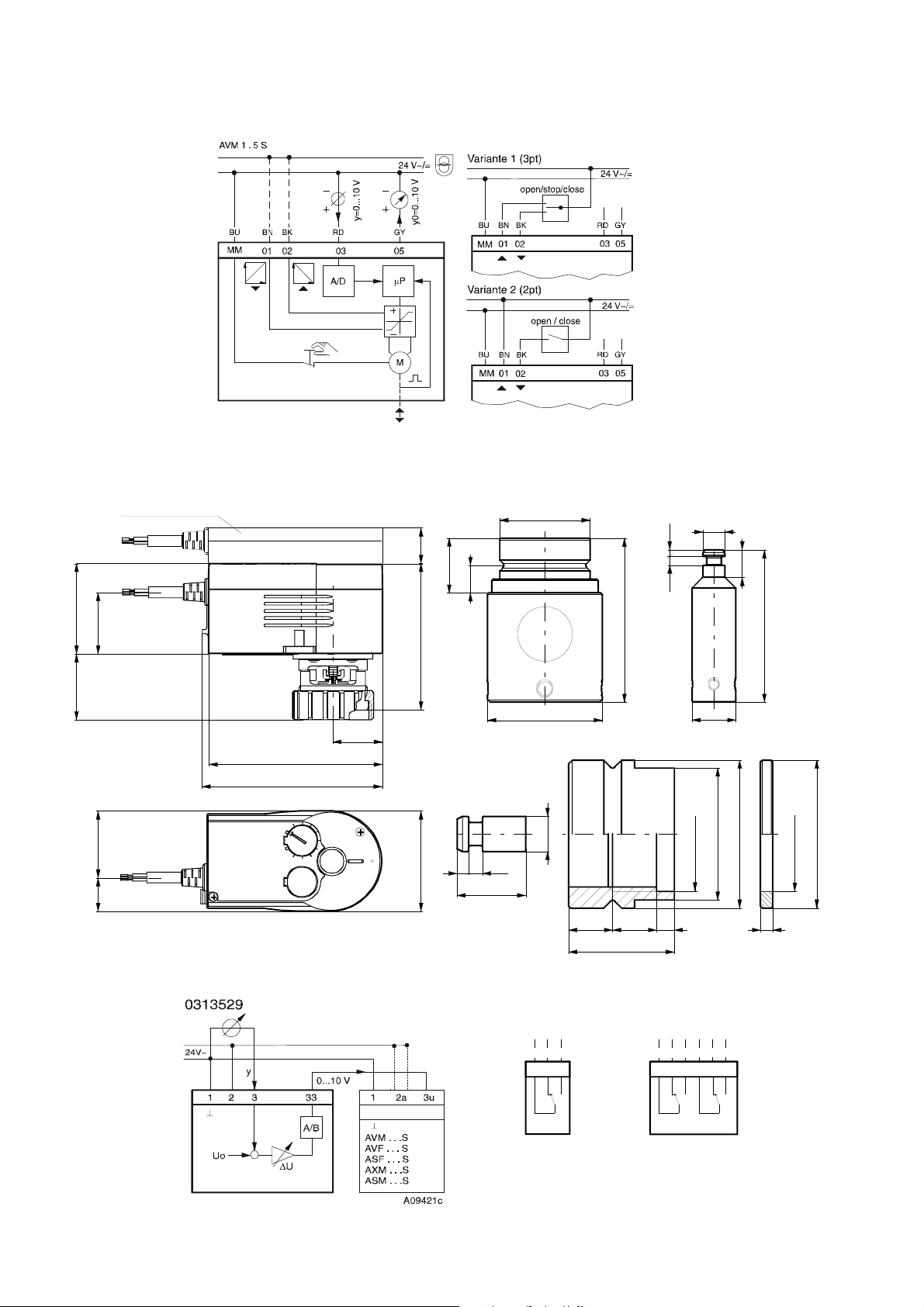
Operation
Depending on how it is connected (see wiring diagram), the actuator can be used as a continuous
0...10 V, a 2-point (open/close) or a 3-point (open/stop/close) drive with intermediate position. The
running time can be matched to requirements using switches S1 and S2 (AVM 105, S1 only). The
characteristic (equal-percentage or linear) can be selected using switch S3. The AVM 105/115 is
combined with valves that have an equal-percentage basic characteristic such as the VUD/BUD and
VUE/BUE valves. The AVM 115 can be fitted to a valve with a linear characteristic (e.g. VUE 050F200),
but the position of the coding switches is important. With the AVM 105, it is not possible to create an
equal-percentage characteristic for a valve with a linear characteristic.
Manual adjustment is performed by disengaging the transmission (sliding switch next to the power
cable) and simultaneously turning, using an Allen key in the insert on the upper part of the drive. 8 mm
of stroke is attained with 1½ turns.
N.B.: After manual adjustment, re-set the sliding switch (engage the transmission).
Connected as a 2-point actuator
Open/close activation can be effected via two wires. Power is applied to the drive via the blue and the
brown wires. On connecting power to the black wire, the valve’s control passage opens. When power
is switched off, the drive goes to the opposite end position and closes the valve.
The unused red and grey wires should not be connected, nor should they come into contact with other
wires. We recommend that you insulate them.
Connected as a 3-point control unit
By connecting power to the wires (brown or black), the valve can be moved to any position. The
coupling rod extends and opens the valve if power is applied to the black wire. It retracts and closes
the valve if power is applied to the blue and the brown wires.
In the end positions (on hitting a stop in the valve or reaching the maximum stroke) or in the event of
an overload, the electronic motor cut-off responds (no end switches). The direction of the stroke can be
changed by swapping the power-supply wires over (BN/BK). The unused red and grey wires should
not be connected, nor should they come into contact with other wires. We recommend that you
insulate them.
Connections for control voltage 0...10 V
The integrated positioner controls the drive as a function of the controller’s positioning signal y.
Direction of operation 1 (mains power on brown wire): the coupling rod extends and opens the valve
(control passage) as the positioning signal rises.
Direction of operation 2 (mains power on black wire): the coupling rod retracts and closes the valve
(control passage) as the positioning signal rises.
The starting point and the control span are both permanently set. There is a split-range unit available
(as an accessory) for setting partial ranges.
After manual adjustment or in the event of a power failure for longer than 5 minutes, the drive
re-adjusts itself automatically, always with the following running times:
AVM 105 35 s
AVM 115 60 s
per MV 505671
iliary change-over contacts 1); MV 505795
iliary change-over contacts 1); MV 505795
(recommended for temperature < 10 °C); MV 505932
2)
130 ; MV 505795
2)
1000 ; MV 505795
2)
5000 ; MV 505795
Sauter Components
7151362003 05

AVM 105S...115S 51.362/3
After power has been applied, the stepping motor moves to the lower stop, connects to the valve
spindle and moves to the upper stop in the valve, thereby determining the closed position. Depending
on the control voltage, any stroke between 0 and 8 mm can then be obtained. Thanks to the
electronics unit, no steps can be lost, and the drive needs no periodical re-adjustment. Parallel
operation of more than one drive of the same type is guaranteed.
The feedback signal y0 = 0...10 V corresponds to the effective stroke of 0 to 8 mm.
If the control signal (0...10 V) is interrupted and direction of operation 1 is connected, the valve closes
fully (0% position).
The valve’s characteristic can be selected using the coding switch. The characteristics can be
generated only if the drive is used as a continuous drive. Other switches enable the running times to
be set. These can be applied irrespective of which function (2-point, 3-point or continuous) has been
chosen.
Coding switch for setting the running time
AVM 1 05S
AVM 115S
Run time
per mm
7,5 s
15 s
Switch coding
1 2 3
On
Off
1 2 3
On
Off
Run time for
8 mm stroke
60 s ± 2
120 s ± 4
Coding switch for selecting the characteristic
AVM 105S
Desired
character.
curve
Equal
percentage
Linear
Linear
Switch coding
1 2 3
On
Off
1 2 3
On
Off
1 2 3
On
Off
Characteristic
curve for valve
v
v
v
Stroke
Stroke
Stroke
Characteristic
curve for drive
Stroke
Stroke
Stroke
Signal
Signal
Signal
= factory setting
B10703
Effective on valve
v
= %
Signal
v
lin
Signal
v
lin
Signal
= factory setting
Sauter
Components
B10704
7151362003 05

51.362/4 AVM 105S...115S
Coding switch for selecting the characteristic
AVM 115S
Desired
character.
curve
Equal
Quadratic
LinearEqual
Linear
percentage
percentage
Switch coding
1 2 3
On
Off
1 2 3
On
Off
1 2 3
On
Off
1 2 3
On
Off
1 2 3
On
Off
Characteristic
curve for valve
v
Stroke
v
Stroke
v
Stroke
v
v
Stroke
Stroke
Characteristic
curve for drive
Stroke
Signal
Stroke
Signal
Stroke
Signal
Stroke
Signal
Stroke
Signal
Effective on valve
v
= %
Signal
v
2
x
Signal
v
lin
Signal
v
= %
Signal
v
lin
Signal
= factory setting
B10705
Split-range unit, accessory 0361529 001
The starting point U
0 and the control span U can be set using the potentiometer. This makes it
possible to activate several regulating units in sequence or in cascade using the controller’s control
signal. The input signal (partial range) is amplified into an output signal of 0...10 V. This accessory
cannot be fitted in the actuator, but should be located externally in an electric distribution box.
CASE Drives PC tool, accessory 0372462 001
CASE Drives enables all the actuator's parameters to be set and viewed on site. Connection is via a
serial port on the PC (laptop) and a socket on the actuator. The set comprises: software including
installation and operating instruction, fitting instructions, connectors, cable (1.2 metres in length) and
an interface converter for the PC. The application is designed for commissioning/ service technicians
and for experienced users.
The last setting (i.e. whether with coding switch or CASE Drives) has priority. This setting is active
when the valve's running time or characteristic is changed via the coding switch. To ensure that the
settings with CASE Drives cannot be overwritten, the coding switch should be removed before setting
values through CASE Drives (special tool included).
Sauter Components
7151362003 05

AVM 105S...115S 51.362/5
Engineering and fitting notes
The ingress of condensate, drops of water etc. along the valve spindle and into the drive should be
prevented.
With the electrical connection, you must also make sure that the cross-section of the supply line is
adapted to the power and length. In any case, however, we recommend that the cross-section should
not be less than a minimum of 0.75 mm
The assembly of actuator and valve is done by fitting and tightening the cap nut without further
adjustment; no tools should be used. The valve spindle and the drive spindle are coupled together
automatically, either by using the manual adjustment facility or by applying power. When dismantling,
first release the drive/valve spindle, then loosen the cap nut.
The actuator is supplied ex works in the middle position.
The combination of stepping motor and electronics unit allows several actuators of the same SUT type
to be run in parallel.
The following accessories can be fitted to each actuator: one set of auxiliary contacts.
The coding switches are accessible via an opening with black lid in the housing cover.
The auxiliary contacts should be screwed onto the drive’s top cover. Before the mechanical connection
can be established, the indicator knob should be removed. A new indicator is then visible on the lid of
the auxiliary contacts.
N.B.: The housing should not be opened.
Fitting outdoors
If the devices are fitted outdoors, we recommend that additional measures be taken to protect them
against the effects of the weather.
Additional technical data
The upper part of the housing, with the lid, indicator knob and the cap, contains the stepping motor and
the SUT electronic control unit. The lower part contains the maintenance-free transmission.
Auxiliary change-over contacts
Switch rating: max. 230 V a.c.; min. current 20 mA at 20 V
Switch rating: max. 4...30 V d.c.; current 1...100 mA
Power consumption:
Type Running time
[s]
AVM 105S F132 35 Operating 2.45 4.75
Standstill 0.35 0.8
60 Operating 4.8 8.5
Standstill 0.35 0.8
120 Operating 2.2 4.25
Standstill 0.35 0.8
AVM 115S F132 60 Operating 4.9 8.7
Standstill 0.35 0.75
120 Operating 2.25 4.3
Standstill 0.35 0.75
CE conformity
EMC Directive 2004/108/EC
EN 61000-6-1
EN 61000-6-3
EN 61000-6-4
2
.
Condition Active power P
[W]
Apparent power S
[VA]
Sauter Components
7151362003 05
51.362/6 AVM 105S...115S
Wiring diagram
Dimension drawing
RD = red
BN = brown
BK = black
BU = blue
GY = grey
A10450
372145, 372286
6345,6
43,5
46,5
23,5
Accessories
0372249 001
Ø33
Ø8
2,5
32
15
5
3,2
60
10
55,8
107,1
Ø42
Ø16
Z10214
35
122
126,7
70
372273
2,5
3,2
Ø8
Ø33
Ø26,5
SW30
Ø33
Ø26,7
15,5
M09743b
24
810 10 4
M10203
Printed in Switzerland
Subject to change.
© Fr. Sauter AG. CH-4016 Basle
7151362003 05
MM 01/02
Sauter Components
372145 002 372145 001
RD BN BK
03
A09782
RD BN BK GN GY VT
A10183
 Loading...