

Page 1
Sauter GmbH
Ziegelei 1
D-72336 Balingen
E-Mail: info@sauter.eu
Tel: +49-[0]7433- 9933-199
Fax: +49-[0]7433-9933-149
Internet: www.sauter.eu
Instruction Manual
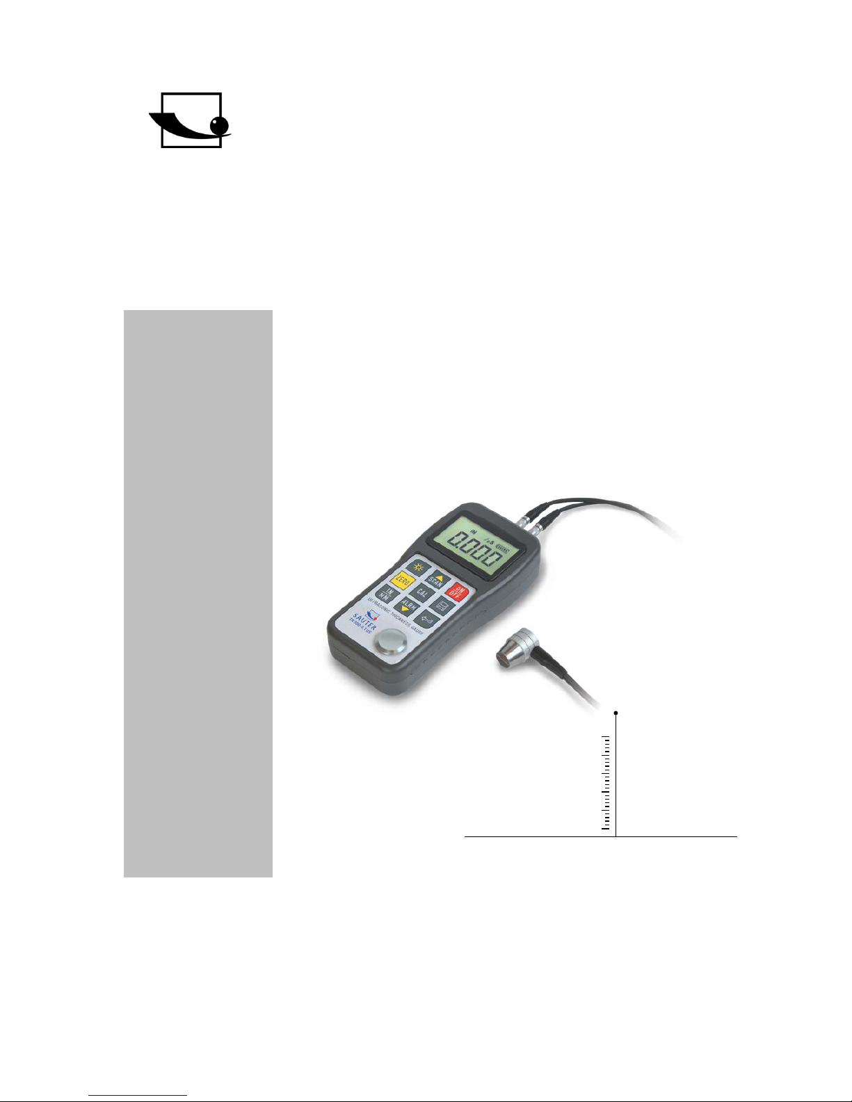
Digital Ultrasonic Thickness Gauge
SAUTER TN-US
Version 1.4
01/2018
GB
TN_US-BA-e-1814
PROFESSIONAL MEASURING
Page 2

2 TN_US-BA-e-1814
GB
SAUTER TN-US
Version 1.4 01/2018
Instruction Manual Ultrasonic Thickness Ga uge
Thank you for buying a SAUTER digital Ultrasonic Thickness Gauge. We hope you
are pleased with your high quality Thickness Gauge with its big functional range.
If you have any queries, wishes or helpful suggestions, do not hesitate to call our
service number.
Summarize:
1 Overview ......................................................................................................... 3
1.1 Product specifications ............................................................................................................. 3
1.2 Main functions .......................................................................................................................... 4
1.3 Measuring principle .................................................................................................................. 4
1.4 Configuration ............................................................................................................................ 5
1.5 Operation conditions ............................................................................................................... 5
2 Structure feature ............................................................................................ 5
2.1 Digital Display ........................................................................................................................... 6
2.2 Keypad definition ..................................................................................................................... 6
3 Preparation ..................................................................................................... 6
3.1 Transducer selection ............................................................................................................... 6
3.2 Conditions and preparation of surfaces ................................................................................ 8
4 Operation ........................................................................................................ 9
4.1 Power on/ off ............................................................................................................................. 9
4.2 Zero adjustment ........................................................................................................................ 9
4.3 Sound velocity calibration ..................................................................................................... 10
4.3.1 Calibration to a known thickness .............................................................................................. 10
4.3.2 Calibration to a known velocity ................................................................................................. 11
4.3.3 Two-point Calibration ................................................................................................................ 11
4.4 How to perform measurements ............................................................................................ 12
4.4.1 Change of measuring sound velocity ....................................................................................... 13
4.5 Scan mode .............................................................................................................................. 13
4.6 Changing resolution ............................................................................................................... 13
4.7 Changing units ....................................................................................................................... 13
4.8 Memory management............................................................................................................. 14
4.8.1 Storing a reading ...................................................................................................................... 14
4.8.2 Clearing a selected file ............................................................................................................. 14
4.8.3 Viewing/ deleting stored records .............................................................................................. 14
4.9 Data printing ........................................................................................................................... 15
4.10 Beep- Mode ............................................................................................................................. 15
4.11 EL Backlight ............................................................................................................................ 15
4.12 Battery information ................................................................................................................ 15
4.13 Auto Power off ........................................................................................................................ 15
4.14 System reset ........................................................................................................................... 16
4.15 Connection to PC ................................................................................................................... 16
5 Servicing ....................................................................................................... 16
6 Transport and Storage ................................................................................ 16
Page 3

TN_US-BA-e-1814 3
Available models: TN 80-0.1US
TN 230-0.1US
TN 300-0.1US
TN 80-0.01US
TN 230-0.01US
TN 300-0.01US
1 Overview
Model TN- US is a digital ultrasonic thickness gauge based on the same operating
principles as SONAR. The instruments are capable of measuring the thickness of
various materials with an accuracy of 0.1/0.01 mm. They are suitable for a variety of
metallic and non- metallic materials.
1.1 Product specifications
Display: 4.5 digits LCD with EL backlight
Measuring range: 0.75 to 300mm (in steel)
Sound velocity: 1000 to 9999m/s
Resolution: TN xx0.1 US: 0,1mm;
TN xx0.01US: 0,1 / 0,01mm
Model TN 80-0.01measures continuously with a resolution of 0.01
Model TN 230-0.01 US as well as TN 300-0.01 are measuring with a
readout of 0.01 up to 200mm
and over this, each device measures with a resolution of 0.1
Accuracy: Models with a resolution of 0.1mm:
0.5% of the measured value +0.04mm
Models with a resolution of 0.01mm: 1% of the meas ur ed value
In dependence on material and environmental conditions.
Units: Metric/ Imperial units selectable
- Four measurements readings per second at single point measurement and ten
per second at Scan Mode.
- Memory up to 20 files (up to 99 values for each file) of stored values
Power supply: 2x AA, 1.5V alkaline batteries
Typical operating time: about 100 hours
(EL backlight off)
Page 4

4 TN_US-BA-e-1814
Transfer to PC: RS-232 serial port for TN xx0.01 US.
No transfer to PC possible at TN xx0.1 US
Dimensions: 150 x 74 x 32 mm
Weight: 245g
1.2 Main functions
- Capable of performing measurements on a wide range of materials including
metals, plastic, ceramics, epoxies, glass and other ultrasonic wave well- conductive materials.
- Various transducer models are available for special applications included
coarse grain material and high temperature applications.
- Zero adjustment function, Sound velocity calibration function
- Two- point calibration function
- Two measurement modes: Single point mode
Scan mode
- Coupling status indicator showing the coupling status
- Battery indication indicates the rest capacity of the battery
- “Auto sleep” and “Auto power off” function to conserve battery’s life
Optional software for TN xx0.01 US to transfer the m emory data to PC
Optional thermal mini-printer to print the measured data via RS-232 port,
available for TN xx0.01 US.
1.3 Measuring principle
The digital ultrasonic thickness gauge determines the thickness of a part or a structure by accurately measuring
The time required for a short ultrasonic pulse generated by a transducer to travel
through the thickness of the material, to reflect from the back or inside surf ace and
be returned to the transducer. The measured two- way transit tim e is divided b y two
to account for the down-and-back travel path, and then multiplied by the velocity of
sound in the material. The result is expressed in following relationship:
2
tv
H
×
=
Where: H ----˃ thickness of the test piece
v ----˃ sound velocity in the material
t ----˃ the measured round-trip transit time
Page 5
TN_US-BA-e-1814 5
1.4 Configuration
Table 1-1
1.5 Operation conditions
Temperature: -20°C up to +60°C
Storage temperature: -30°C up to 70°C
Relative humidity: ≤ 90%
In the surrounding environment any kind of vibrations should be avoided, as well as
magnetic fields, corrosive medium and heavy dust.
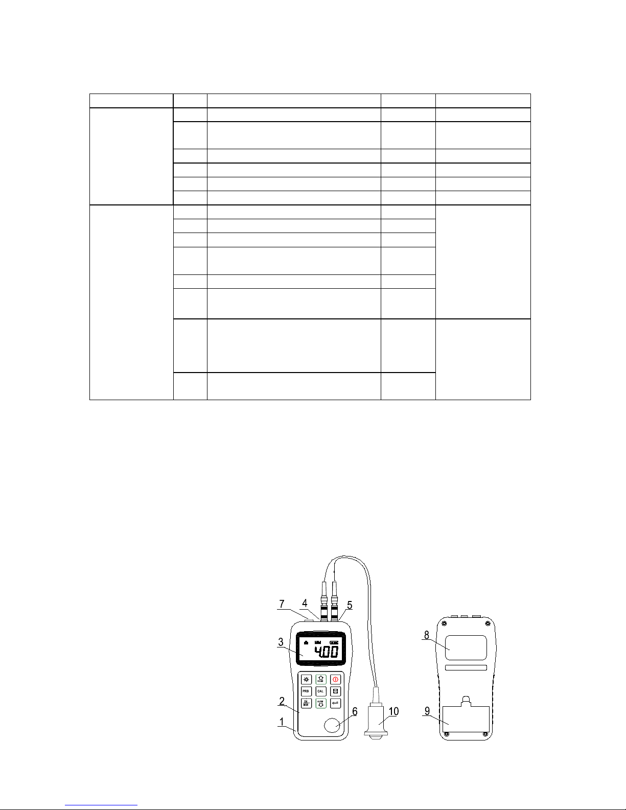
2 Structure feature
1 Main body
2 Keypad
3 LCD Display
4 Pulser socket
5 Receiver socket
6 Control plate
7 Communication port
8 Label
9 Battery cover
10 Ultrasonic sensor
No.
Item
Quantity
Note
Standard
configuration
1
Main body
1
2
Transducer
1
Depends on the
model
3
Coupling medium
1 4
Transport case
1 5
Instruction manual
1 6
Alkaline Battery
2
AAsize
Optional
Configuration
Re-order
7
Transducer: ATU-US 01
1
see table
3-1
8
Transducer: ATU-US 02
1
9
Transducer: ATB-US 02
1
10 Transducer: ATU-US10
90° angle
1
11
Transducer: ATU-US09
1
12 Transducer: ATB-US01
1
13
14
15
Data Pro Software ATU-04
Plug-In Software AFI-1.0
USB Komm.kabel FL-A01
1
1
1
for PC, only at
models with
resolution
TN xx0.01 US
16
Coupling medium
ATB-US03
1
POWER: 2 X 1.5V
SN:
ULTRASONIC
THICKNESS GAUGE
Page 6
6 TN_US-BA-e-1814
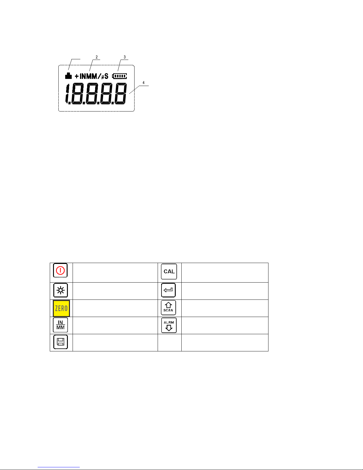
2.1 Digital Display
1 Coupling status:
Indicates the coupling status. While measurements are taken, the coupling status
should be on. If it isn’t or if it isn’t stable, the instrument has got difficulties in achieving stable measurements and the thickness value displayed will most likely be erroneous.
2 Unit:
Current unit system. MM or IN for thickness value.
M/S or IN/µS for sound velocity.
3 Battery information:
Displays the rest capacity of the battery.
4 Information Display:
Displays the measured thickness value, the sound velocity and shows hints of the
current operation.
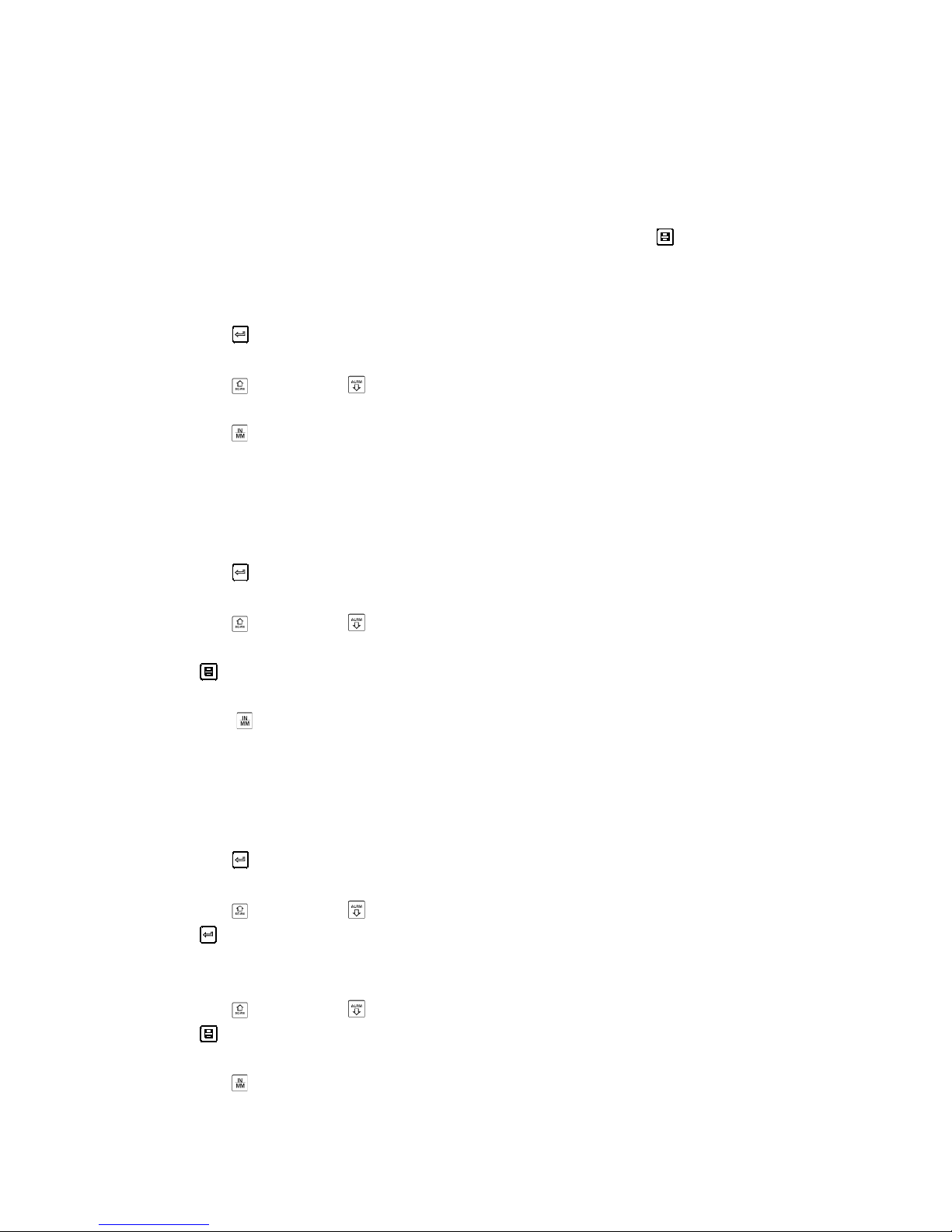
2.2 Keypad definition
Turn the in strument on/off
Sound velocity calibration
Turn on/off the EL back-
light
Enter
Zero operation
Plus;
Turn on/off Scan mode
Unit switch between Met-
ric and Imperial system
Minus;
Turn on/off the beep mode
Data Save or Data Delete
3 Preparation
3.1 Transducer selection
With this instrument it is possible to measure a wide range of different materials,
started from various metals to glass and plastics. These different types of material
require the usage of different transducers. Choosing the correct transducer is the
most important thing to perform accurate and reliable measurements. Generally
1
Page 7

TN_US-BA-e-1814 7
speaking, the best transducer for an operation is the one that sends sufficient ultrasonic energy into the material to be measured in the way that a strong, stable echo is
to be received in the instrument. There are several factors that affect the strength of
the traveling ultrasoun d. They are descr i be d as followed:
Initial signal strength: The stronger a signal is at the beginning, the stronger its
echo will return. Initial signal strength is mainly a factor of the size of the ultrasound
emitter in the transducer. A large emitting area will send more energy into the material being measured than a small one. Thus, a so-called “1/2 inch” transducer will emit
a stronger signal than a “1/4 inch” transducer.
Absorption and scattering: As the ultrasound travels through a material, it is partly
absorbed. If the material has got any grain structure, the sound waves will start scattering. Both of these effects reduce the strength of the waves and thus the instrument’s ability to detect the returning echo. Ultrasound of higher frequency is absorbed and scattered more tha n ultr asound of lower frequency.
While it may seem that using a lower frequency transducer is better in every instance, it should be mentioned that low frequencies are less directional than higher
ones. Thus, a higher frequency transducer is a better choice for detecting the exact
location of small pits or flaws in the material to be measured.
Geometry of the transducer:
The physical constraints of the environment sometimes determine a transducer’s
suitability for an operation. Some transducers are simply too large to be used in a
confined area. If the available surface area for contacting with the transducer is limited, the usage of a transducer with a small surface is required.
Measurements on a curved surface, in example an engine cylinder wall, will require a
transducer with an adapted surface.
Temperature of the material: If exceedingly hot surfaces are to be measured, high
temperature transducers must be used. These transducers are built with special materials and techniques that allow them to withstand high temperatures without being
damaged. Additionally, care must be taken if a “Zero adjustment” or a “Calibration to
known thickness” is being performed with a high temperature transducer.
The selection of a proper transducer is often a matter of tradeoffs between various
characteristics. Sometimes it is necessary to experience with a variety of transducers
in order to find the one that works well for a special operation.
The transducer is the “business end” of the instrument.
It transmits and receives ultrasonic sound waves which the instrument uses to calculate the thickness of the material being measured. The transducer is connected to the
instrument via the attached cable and two coaxial connectors. The transducer has to
be installed correctly to get reliable measurement results. Each plug must be fit into
the adequate socket in the instrument.
Page 8

8 TN_US-BA-e-1814
Below there are shown two photos and a short description of the instruction use of a
transducer.
The left f igure is a bottom view of a typical transducer. The two semicircles are visibly
separated in the middle of the surface. One of the semicircles is conducting the echoed sound back into the transducer. When the transducer is placed against the material being measured, this is the area directly beneath the centre of the measured surface.
The below figure is a top view of a typical transducer.
It is pressed against the top with the thumb or the index finger to hold the transducer
in place. Only m oderate pressure is sufficient to keep it stationary. Its surface must
be placed flat against the surfac e o f the material.
Table 3-1 Transducer s el ecti on
3.2 Conditions and preparation of surfaces
At any kind of ultrasonic measurement, the shape and roughness of the surface being tested are of param ount importance. Rough and uneven surfaces m ay limit the
Model
Freq
MHz
Ø
mm
Measurement Range
Lower
limit
Description
ATU- US 01
2,5
14
3.0mm~300.0mm
(in steel)
40mm(grey
Cast iron HT200)
20mm
For thick, highly
attenuating
or highly scattering
materials
ATU- US 09
5
10
1.2mm~230.0mm
(in steel)
Φ20mm×
3.0mm
normal
measurement
ATU- US 10
5
10
1.2mm~230.0mm
(in steel)
Φ20mm×
3.0mm
Normal Measurement
/ 90°angle
ATU- US 02
7
6
0.75mm~80.0mm
(in steel)
Φ15mm×2.0mm
For thin pipe
walls or small
curvative pipe
walls
ATB-US01
5
6
0.75mm~80.0mm
(in steel)
Φ15mm×2.0mm
For thin material
ATB- US 02
5
12
3~200mm
(in steel)
30mm
For high tem-
perature (lower
than 300°C)
measurement
Page 9

TN_US-BA-e-1814 9
penetration of the ultrasound through the material resulted by an unstable and therefore unreliable measurement.
The surface being measured should be clean and free of any small particulate matter, rust or scale. The transducer must be placed on a flat and even surface. To get it
clean it might be helpful to use a wire brush or a scraper. In more extreme cases,
rotary sanders or grinding wheels may be used. Care must be taken to prevent surface gouging which inhibits a proper transducer coupling. Extremely rough surfaces
such as the pebble-like finish of cast iron will be measured quite complicated. These
kinds of surfaces comport to the sound beam like frosted glass on light: the beam
becomes diffused and scatt er e d in all direc ti o ns.
In addition to this, rough surfaces account for an excessive wear of the transducer,
especially when it is “scrubbed” along the surface. T ransducers should be inspected
time by time if there are any signs of abrasion.
If the transducer is worn off on one side more than on the other, the sound beam
penetrating the test material may no longer be perpendicular to the surface of the
material. In this case, it is difficult to exactly locate tiny irregularities in the material, as
the focus of the sound beam no longer lies directly beneath the transducer.
4 Operation
4.1 Power on/ off
The instrument is turned on by pressing the key.
The instrument has got a special memory where all settings are stored even if it was
powered off.
4.2 Zero adjustment
The key is used to „zero“ the instrument. It is just the same way as a mechanical
micrometre is zeroed. If the instrument isn’t zeroed correctly, all the measurements
taken may be in error by an initially incorrect value. W hen the instrument is zeroed,
this fixed error value is measured and automatically corrected for all subsequent
measurements.
The instrument is “zeroed” as follows:
1) The transducer is to be plugged into the instrument in the way that all connectors
are fully engaged.
It has to be checked that the surface of the transducer is clean and free of any debris.
2) The key has to be pressed.
3) The key and the key has to be used to scroll on the sensor model currently
used. The right choice of the sensor is of high importance.
4) A single droplet of ultrasonic couplant is to be applied to the metallic control plate.
Page 10

10 TN_US-BA-e-1814
5) The transducer is to be pressed flat against the surface of the control plate. Now
you can see the value 4mm, because the thickness of the control plate is 4mm and
the instrument is calibrated of 4mm.
6) Now the transducer is to be removed from the control plate.
At this point, the instrument has successfully calculated its internal error factor and
will compensate for this value in all following measurements.
When performing a “Zero adjustment”, the instrument will always use the sound velocity value of the in-built control plate, even if any other velocity value has been entered for making actual measurements.
Though the last “Zero adjustment” will be stored it is generally recommended to perform a “Zero adjustment” whenever the instrument is turned on as well as, if a different transducer is used. T his wa y it is ensured that the instrument has been zeroed
correctly.
The key has to be pressed and the Zero adjustment is terminated. The instrument
returns to the measure ment mod e.
4.3 Sound velocity calibration
In order to performing accurate measurements, the instrument must be set to the correct sound velocity of the material being measured. Different types of material have
got different inherent sound velocities. If the instrument isn’t set to the correct sound
velocity, all the m easurements will be deficient by some fixed percentage.
The One-point calibration is the simplest and most commonly used calibration pro-
cedure, optimizing linearity over large ranges.
The Two-point calibration has got higher accuracy over small ranges by calculating
the Zero adjustment and sound velocity.
Note: One- and Two-point calibrations should only be performed on material where
the paint or the coating is removed; if not, it will result in a multi material velocity calculation which is surely deviating from the actual velocity of the material intended to
be measured.
4.3.1 Calibration to a known thickness
1) A Zero adjustment has to be perfor me d.
2) A couplant has to be applied to the sample piece.
3) The transducer has to be pressed against the sample piece, making sure that the
transducer is placed flat on it.
The display now shows any thickness value and the coupling status indicator should
appear steadily.
4) As soon as a stable reading is achieved, the transducer has to be rem oved. If the
displayed thickness now distinguishes from the value shown while the transducer
was coupled, step 3 has to be repeated.
5) The key has to be pressed to activate the calibration mode. The MM (or IN)
symbol should start flashing.
Page 11

TN_US-BA-e-1814 11
6) The and the key has to be used to adjust the displayed thickness up or down
until the thickness of the sample piece is matched.
7) The key has to be pressed again. The M/S (or IN/µS) should start flashing. No w
the sound velocity value, which has been calculated based on the thickness value
that was entered, is displayed.
8) The key has to be pressed again to exit the calibration mode and return to the
measurement mode.
The instrument is now ready to perform measurements.
4.3.2 Calibration to a known velocity
Note: This procedure requires that the sound velocity of the material being measured, is known. A table of the most common materials and their sound velocities can
be found in Appendix A of this manual.
1) The key is to be pressed to activate the calibration mode. The MM (or IN) symbol should start flashing.
2) The key is to be pressed again, so that the symbols
M/S (or IN/µS) are flashing.
3) The and the key have to be used to adjust the sound velocity up and down
until it matches the sound velocity of the material being measured. The key can
also be pressed to switch among the pre-set, commonly used velocities.
4) To quit the calibration mode, the key has to be pressed and the instrument is
ready to perform measurements.
To achieve the most accurate measurement results, it is generally advisable to calibrate the instrument to a sample piece of known thickness. The composition of materials (and thus, its sound velocity) sometimes varies from lot to lot and from manufacturer to manufacturer.
Calibration to a sample of known thickness ensures that the instrument is set as
closely as possible to the sound velocity of the material being measured.
4.3.3 Two-point Cal ibration
Note: This procedure requires that the testing person has got two known thickness
points on the test piece which are representative of the range being measured.
1) A Zero adjustment has to be perfor me d.
2) A couplant has to be applied to the sample piece.
3) The transducer has to be pressed against the sample piece at the first / second
calibration point. It has to be made sure that the transducer is placed flat on the surface of the sample. Now the display should show any (probably incorrect) thickness
value and the coupling status indicator should appear steadily.
4) As soon as a stable m easurement is achieved, the transducer is to be removed. If
the displayed thickness distinguishes from the value shown while the transducer was
coupled, step 3 is to be repeated.
5) The key is to be pressed. The MM (or IN) symbol should start flashing.
Page 12

12 TN_US-BA-e-1814
6) The and the key have to be used to adjust the sound velocity up and down
until it matches the sound velocity of the sample piece.
7) The key has to be pressed. 1OF2 will be shown on the display. Steps 3 to 6 are
to be repeated on the second calibration point.
8) The key has to be pressed, so that the symbol M/S (or IN/µS) is flashing. The
sound velocity value, which was calculated based on the thickness values being entered in step 6, will now be displayed.
9) To quit the calibration mode, the key has to be pressed again and the instrument is ready to perform measurements within its range.
4.4 How to perform measurements
The instrument always stored the last measured value until a new measurement is
made. In order for the transducer working in the right way there may not be any gaps
between the contact area of the sensor and the surface of the material being measured. This is accomplished with the coupling fluid, commonly called “couplant”. This
fluid serves to “couple” or transfer the ultrasonic sound waves from the transducer,
into the material and back again.
Therefore a small amount of couplant should be applied onto the surface of the material, before measurements are performed. Typically, a single droplet is sufficient.
After the couplant is applied, the transducer has to be pressed firmly against the area
being measured. The coupling status indicator should appear on the display as well
as a digit number. If the instrument has been “zeroed” properly and if it has been set
to the correct sound velocity, the actual thickness of the material directly beneath the
transducer will be indicated as a number in the display.
If the coupling status indicator doesn’t appear or if it isn’t stable or if the numbers on
the display doesn’t seem to be correct, it has to be checked whether there is an adequate film of couplant beneath the transducer and whether the transducer is placed
flat onto the material.
If conditions persist, sometimes it is necessary to select a different transducer (size
or frequency) for the material intended to be measured.
While the transducer is in contact with the material, the instrument will perform four
measurements every second, updating its display as it does so.
If the transducer is removed, the display will hold the last measurement performed.
Note: Occasionally a small film of couplant will be drawn out between the transducer
and the surface, as the transducer is removed. If this happens, the instrument may
perform a measurement through this couplant film, resulting in an erroneously measurement. This is comprehensible because one thickness value is observed while the
transducer is in place and the other value is observed after the transducer is removed.
In addition, measurements performed through very thick paint or coatings may result
in the paint or coating being measured rather than the material intended.
Page 13

TN_US-BA-e-1814 13
The responsibility for a proper use of the instrument, as well as the recognition of
these types of phenomenon solely depends on the user of this instrument.
4.4.1 Change of measuring sound velocity
In appendix A you find the different sound velocities, that are to be applied for measuring the different materials.
To change the sound velocity of your instrument please proceeds as follows:
1. Press the CAL key twice until M/S sy mbol be g i ns to flash .
2. Then, press the SCAN or ALARM key to change the sound velocity
3. To safe the settings, please press the Cal key.
4.5 Scan mode
While the instrument excels in making single point measurements, it is sometimes
necessary to examine a larger region, searching for the thinnest point. This instrument includes a feature, called SCAN- Mode, which allows to do just that.
During normal operation, it performs and displays four measurements every second
which is adequate for single measurements. In SCAN- Mode, however, the instrument performs ten measurements every second and displays the readings while
scanning. While the transducer is in contact with the material to be measured, it is
always keeping track to finding the lowest measurements. The transducer may be
“scrubbed” across the surface, any brief interruptions of the signal will be ignored. If it
loses contact with the surface for more than two seconds, the instrument will display
the smallest measurement it found.
If the SCAN- Mode is turned off, Single point Mode will be automatically turned on.
The SCAN- Mode is turned on/ off by the following steps:
The key has to be pressed to switch on/ off the SCAN- Mode. The current condition of it will be displayed on the display.
4.6 Changing resolution
The instrum ent TN xx-0.01 US has got a selectable display resolution, which is 0.1
and 0.01mm.
If the key is pressed while turning on the instrument,
The resolution will be switched between “high” and “low”.
This function is not availabl e for TN xx-0.1 US, which is fixed to 0.1mm.
4.7 Changing units
On the measurement m ode, the key has to be pressed to switch back and forth
between imperial and metri c uni ts .
Page 14
14 TN_US-BA-e-1814
4.8 Memory management
4.8.1 Storing a reading
There are 20 files (F00-F19) which can be used to store the measurement values
inside the instrument.
At most 100 records (thickness values) can be stored in each file. The measured
thickness value will be saved to the current file by pressing the key after a new
measurement reading appears. It will be added as the largest record of the file.
To change the destination file to store the measured values, the following steps are
to be carried out:
1) The key is to be pressed to activate the data logging functions. T he curr e nt file
name and the total record count of the file will be displayed.
2) The key and the key have to be used to select the desired file to set as
current file.
3) The key has to be pressed to exit the data logging functions any time wanted.
4.8.2 Clearing a selected file
It may be required to clear the contents of an entire file completely of all measurements. With this a new list of measurements can be stared, beginning with L00.
The procedure is outlined in the following steps:
1) The key is to be pressed to activate the data logging functions. T he curr e nt
file name and the total record count of the file will be displayed.
2) The key and the key have to be used to scroll to the file that shall be cleared
of all measurements.
3) The key has to be pressed on the desired file. The file will be automatically
cleared and display “-DEL”.
4) The key has to be pressed to exit the data logging functions any time as
wanted to return to the measurement mode.
4.8.3 Viewing/ deleting stored records
With this function a record can be viewed/ deleted in a desired file previously saved
in memory, following these steps:
1) The key is to be pressed to activate the data logging functions. T he curr e nt file
name and the total record count of the file will be displayed.
2) The key and the key have to be used to select the desired file.
3) The key has to be pressed to enter the selected file.
The current record number will be displayed (i.e. L012) and as well the record con tents.
4) The key and the key have to be used to select the desired record.
5) The key has to be pressed on the desired record.This record will be
automatically deleted and “-DEL” is displayed.
6) The key has to be pressed to exit the data logging functions to return to the
measurement mode.
Page 15

TN_US-BA-e-1814 15
4.9 Data printing
At the end of the inspection process or at the end of the day, it may be required the
readings being transferred to a computer. This procedure is only possible with
TN xx-0.01 US, not with TN xx-0.1 US:
1. Before printing, one connection plug of the print cable (optional parts) has to be
inserted into the socket on the up-left of the main body and the other plug into the
communication socket o f the mini-printer.
2. The key has to be pressed to activate the data logging functions.
3. The key and the key have to be used to select the desir ed fil e.
4. The key has to be pressed to print the selected file.
With this operation all the data in the current file will be sent to the mini-printer
via RS-232 port and will be printed.
5. The key has to be pressed to exit the data logging functions to return to the
measurement mode.
4.10 Beep- Mode
When the beep is set to ((On)), a short hoot will be heard each time while pressing
the key, on each measurement or if the measured value exceeds the tolerance limit.
The key has to be pressed to switch the Beep-Mode on and off. The current BeepMode will be displayed.
4.11 EL Backlight
With the background light, it is convenient to work in even dark condition. The key
has to be pressed to switch on or off the background light any moment it is needed
after having powered on the instrument.
As the EL light will consume much power it only has to be turned on if necessary.
4.12 Battery information
Two AA size alkaline batteries are needed as power source. After several hours’ usage of the preset batteries, the battery symbol on the screen will be shown as .
If battery capacity runs out, the battery symbol will be shown and it will begin to
flash. In this case, the batteries should be replaced.
If the instrument isn’t used for a longer period, the batteries have to be removed.
4.13 Auto Power off
The instrument features an “auto power off”- function designed to conserve battery
life. If it is not in use for 5 minutes or more, it will turn itself off. If the voltage of the
battery is too low this function will also work.
Page 16

16 TN_US-BA-e-1814
4.14 System reset
The key has to be pressed while powering on the instrument: factory defaults will
be restored.
All the memory data will be cleared during system reset. T he only time this might be
helpful is if the parameter in the instrument was somehow corrupted.
4.15 Connection to PC
TN xx-0.01 US is equipped with a RS-232serial port. Using the accessory cable, the
instrument has got the ability to connect to a PC or an external storage device.
Measurement data stored in the memory can be transferred to the PC through the
RS-232 port. For detailed information of the communication software and its usage,
refer to the software manual .
5 Servicing
If there should appear some abnormal phenomena to the instrument, please do not
dismantle or adjust any fixed assembly parts on your own. Instead of this, the present
warranty card has to be f illed out and the instrument has to be sent to us. The warranty service can be carried on.
6 T ransport and Storage
1) The instrument has to be kept away from vibration, strong magnetic fields, corrosive medium, dumpiness or dust. Storage in ordinary temperature.
Appendix A Sound Velocities
Material
Sound Velocities
In/us
m/s
Aluminium
0.250
6340-6400
Steel, common
0.233
5920
Steel, stainless
0.226
5740
Brass
0.173
4399
Copper
0.186
4720
Iron
0.233
5930
Cast Iron
0.173-0.229
4400-5820
Lead
0.094
2400
Nylon
0.105
2680
Silver
0.142
3607
Gold
0.128
3251
Zinc
0.164
4170
Titanium
0.236
5990
Tin
0.117
2960
Epoxy resin
0.100
2540
Page 17

TN_US-BA-e-1814 17
Appendix B Application Notes
Measuring pipe and tubing
When a piece of pipe is measured to determine the thickness of the pipe wall, the
orientation of the transducer is of importance. If the diameter of the pipe is larger than
approximately 4 inches, measurement should be performed with the transducer orientated in the way that the gap in the surface of the sensor is perpendicular (at right
angle) to the long axis of the pipe.
For smaller pipe diameters, two measurements should be performed, one with the
surface gap of the sensor perpendicular, another with the gap parallel to the long axis
of the pipe. The sm aller one of the displayed values should be taken as the thickness
of that point.
Measuring hot surfaces
The sound velocity through a substance is dependent on its temperature. As materials heat up, the velocity of sound through them decreases. In most applications with
surface temperatures of less than 100°C, no special procedures must be observed.
At temperatures above that point, the change in sound velocity of the material being
measured starts having a noticeable effect upon ultrasonic measurement. At such
elevated temperatures it is recommended to first performing a calibration on a sample piece of known thickness, which is at or near the temperature of the material being measured. This will allow the instrument to correctly calculate the sound velocity
through the hot material .
When performing measurements on hot surfaces, it may also be necessary to use a
specially constructed high-temperature transducer. These transducers are built of
materials which can withstand high temperatures.
It is also recommended that the sensor has to be left in contact with the surf ace for a
short time in order to acquire a stable measurement. While the transducer is in contact with the hot surface, it will be heated up and with thermal expansion and other
effects, the accuracy of measurement may adversely be affected.
Ice
0.157
3988
Nickel
0.222
5639
Plexiglass
0.106
2692
Polystyrene
0.092
2337
Porcelain
0.230
5842
PVC
0.094
2388
Quartz glass
0.222
5639
Rubber, vulcanized
0.091
2311
Teflon
0.056
1422
Water
0.058
1473
Page 18

18 TN_US-BA-e-1814
Measuring laminated mat erials
Laminated materials are unique because of their density (and therefore sound velocity) may considerably vary from one piece to another. Some lam inated materials may
even exhibit noticeable changes in sound velocity across a single surface. The only
way to a reliable measurement is to perform a calibration on a sample piece of
known thickness. Ideally, this sample material should be a part of the same piece
being measured, or at least from the same lamination batch. The effects of variation
of sound velocity will be minimized by calibrating each test piece individually.
An additional important consideration is, that any included air gaps or air pockets will
cause an early ref lection of the ultrasound beam. This will be noticed as a sudden
decrease in thickness in an otherwise regular surface. While this may impede accurate measurement of the total material thickness, it does positively indicate any air
gaps in the laminate.
Suitability of materials
Ultrasonic thickness measurement relies on passing a sound wave through the material being measured. Not all materials are suited to transmitting sound. Ultrasonic
thickness measurem ent is practically found in a wide
variety of materials including metals, plastic and glas s.
Materials which are difficult include some cast materials, concrete, wood, fibreglass
and some rubber.
Couplants
Every ultrasonic application requires some medium to couple the sound from the
transducer to the tested material. Typically, a high viscosity liquid is used as the medium. The sound used in ultrasonic thickness measurement doesn’t travel through air
efficiently.
A wide variety of couplant materials may be used. Propylene glycol is suitable for
mostly all applications. In difficult applications, where a maximum transfer of sound
energy is required, gl ycerine is recommended. However, on some metals glycerine
may promote corrosion by means of water absorption, which is undesirable.
Other suitable couplants for measurements at normal temperatures may include water, various oils and greases, gels and silicone fluids. Measurements at elevated
temperatures will require specially formulated high temperature couplants.
Inherent in ultrasonic thickness measurement is the possibility that the instrument will
use the second rather than the first echo from the back surface of the material being
measured while being in standard pulse-echo mode.
This may result in a thickness reading that is TWICE what it should be.
The responsibility of a proper use of the instrument and the recognition of these
types of phenomenon solely rest with the user of the instrument.
Annotation:
To have a look at the CE Declaration of Conformity, please click onto the following
link: https://www.kern-sohn.com/shop/de/DOWNLOADS/
 Loading...