

Page 1
Sauter GmbH
Ziegelei 1
D-72336 Balingen
E-Mail: info@sauter.eu
Tel: +49-[0]7433- 9933-199
Fax: +49-[0]7433-9933-149
Internet: www.sauter.eu
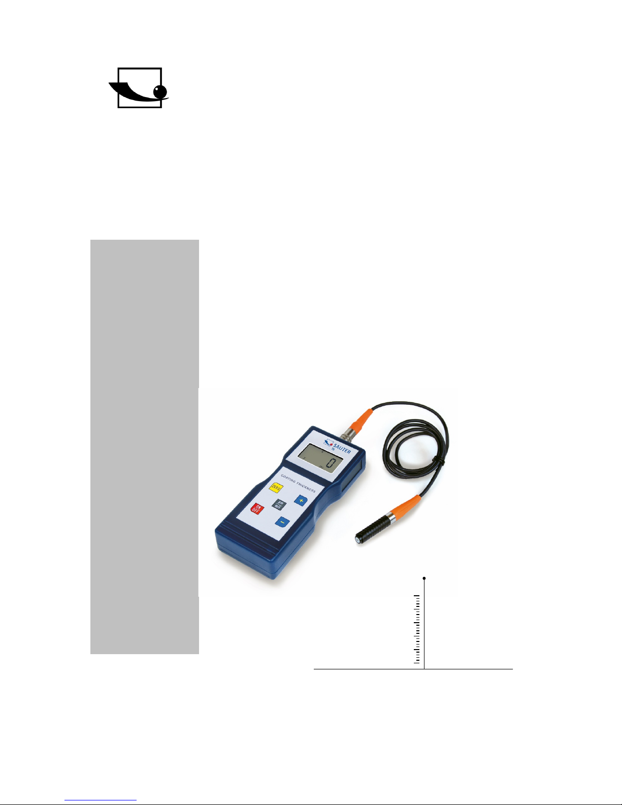
Instruction Manual
Digital Coating Thickness Gauge
SAUTER TB
Version 1.3
08/2017
GB
TB-BA-e-1713
PROFESSIONAL MEASURING
Page 2

2 TB-BA-e-1713
GB
SAUTER TB
Version 1.3 08/2017
Instruction Manual
Digital Coating Thickness Gauge
Thank you for buying a SAUTER digital Coating Thickness Gauge. We hope you are
pleased with your high quality Thickness Gauge with its big functional range.
If you have any queries, wishes or helpful suggestions, do not hesitate to call our
service number.
Models:
- TB 1000-0.1 F
- TB 1000-0.1 N
- TB 1000-0.1 FN
- TB 2000-0.1F
Summarize:
1 Features .......................................................................................................... 3
2 Specifications ................................................................................................ 3
3 Front panel description ................................................................................. 4
4 Measuring Procedure .................................................................................... 5
5 Offset-Accur ................................................................................................... 5
6 Calibration (Adjustment) ............................................................................... 5
7 Batteriewechsel ............................................................................................. 6
8 Adjustment foils ............................................................................................. 6
9 Correct handling at coating thickness measurement with external
sensors ...................................................................................................................... 6
10 Trouble-shooting ........................................................................................... 7
Page 3

TB-BA-e-1713 3
This coating thickness gauge is small in size, light in weight and easy to carry. Although it is complex and advanced, it is convenient to operate. Its ruggedness will
allow many years of use if all the instructions are followed carefully.
Please keep this instruction manual always within reach!
Annotation: It is strongly recommended to adjust the new instrument before
the first use, as described in paragraph 9. By doing this, you will achieve a
much better measurement result right from the start.
1 Features
» This instrument meets the stan dards o f bot h , ISO 21 78. It is suitable for the laboratory and for use in “harsh field conditions”.
» The F-mode measures the coating thickness of nonmagnetic materials, e.g. paint,
plastics, porcelain enamel, copper, zinc, aluminium, chrome, lacquer layers, galvanised or phosphorescent coatings, alloy etc.
These layers shoul d b e locat ed on mag n et ic metals e.g. steel, iron, nickel etc.
» In N-mode, the coating thickness of nonmagnetic coatings can be measured, which
is located on nonmagnetic metals. It is used to measure anodizing, varnish, paint,
enamel, plastic coatings, powder coatings etc. These layers should be located on
nonmagnetic metals e.g. aluminiu m, br ass , n onmagnetic stainless steel and others.
» Automatic „Power-off“to preserve batteries
»Selectable units: mm, µm, inch (mil)
»Display with backlight enables exact reading of the measurement results.
2 Specifications
Display: 4 digits, 10mm LCD, with backlight
Measurement range: 1000 μm and 2000µm
Resolution: 0,1 µm (0 bis 99,9 µm), 1 µm (100 µm bis 1000µm
bzw. 2000µm beim TB 2000-0.1F)
Accuracy:
Following accuracy is given for the models TB 1000-0.1F, TB 1000-0.1N as well as
TB 1000-0.1FN:
Page 4

4 TB-BA-e-1713
- Standard: 3% of the measured value or min. ± 2.5 µm
Is valid within a tolerance range of ± 100 μm around the individually measured range,
if a two-point calibration has been performed within this tolerance range.
For model TB 2000-0.1F accuracy is:
- Standard: 5% of the measured value or min. ± 2.5 µm
Is valid within a tolerance range of ± 100 μm around the individually measured range,
if a two-point calibration has been performed within this tolerance range.
- Off-Set Accur Mode: 1% of the measured value or min. ± 1.0 µm
It is valid within ± 50 μm around the Off-Set Accur point.
Note: All tolerances are valid after the adjustment procedure!
- Smallest measuring surface: 6mm
Power supply: 4x1,5 AA batteries, included in standard delivery
Operating conditions: Temperatures 0 up to 50 °C
Humidity ≤ 80 %
Dimensions: 161 x 69 x 32 mm
Weight: about 260 g (including batteries)
Scope of delivery: - Transport case
- Instr u ct ion man ual
- Instrument and sensor(s)
- 1 set adjus t me nt f oil s , available at every model
- Base plate (aluminium or steel or both at type FN)
3 Front panel description
3-1 Sensor
3-2 Display
3-3 Zero-key
3-4 Plus- key
3-5 Minus- key
3-6 Power- on/ Power- off key
3-7 µm/ mil key
3-8 Battery compartment/ cover
At backside of housing
3-1
3-2
3-3
3-4
3-5
3-6
3-7
3-8
Page 5

TB-BA-e-1713 5
4 Measuring Procedure
4.1 The Power- key 3-6 has to be pressed to turn on the power. “0” appears on the
display 3-2.
Note: The instrument will auto- calibrate, as soon as switched on.
Please pay attention to the sensor. During the initial calibration, the sensor should be
located neither in direct surroundings of the base plate nor other magnetic materials.
4.2 The sensor has to be located onto the coating to be meas ur ed .
The coating thickness will now be displayed.
4.3 To perform the next measurement, the sensor has to be lifted for more than 1cm
off the base material and step 4.2 has to be repeated .
4.4 In case of inaccuracies to the measurement result, it is recommended to
calibrate the instrument before taking measurements, as described in chapter 6.
4.5 The instrument can be switched off by the Power- on/ Power- of f key 3-6. The
gauge switches off automatically 2 minutes after the last key- operation.
5 Offset-Accur
With this instrument, you have got the possibility to improve the measurement result
essentially by using the OFFSET-Accur function. Therefore, it is necessary to calibrate the gauge with a reference coating in the typically measured range. This kind of
fine adjustment can be also done with the calibration foils, included in delivery. Ideally, this adjustment should be done on the base material which is actually used for
the real measurement instead on the base plate, included in delivery.
5.1 The result of the initially measurement is still shown on the display (as performed
in 4.2).
5.2. The reading on the display can be corrected by pressing the Plus- key or the Minus- key. During this operation, the sensor has to be removed from the base plate or
the part going to be measured.
6 Calibration (Adjustment)
6.1 Zero calibration for „Fe“ and „NFe“ should be done separately. If you take the iron
base plate, you will have to insert the F-sensor and „Fe“will be displayed. Or you take
the base plate of aluminium; then you will have to insert the FN-sensor and "NFe"“will
be displayed.
Page 6

6 TB-BA-e-1713
The sensor 3-1 has to be placed carefully onto the base plate. The Zero-key 3-3 has
to be pressed and “0” will be displayed, without lifting the sensor from the base plate.
Annotation: Zero ca libration is not valid, if the sensor does not contact the calibration plate directly or any other uncoated base material.
6.2 An appropriate calibration foil has to be chosen according to the typical measurement range.
6.3 This one has to be put onto the base plate or another uncoated base mater i al .
Note: The sensor has to be located min. 3mm distant from the edge of the base
plate.
6.4 The sensor 3-1 has to be placed carefully onto the calib ration foil and then it has
to be lifted. Now the result is displayed. This can be corrected by pressing the Pluskey 3-4 or the Minus- key 3-5. For doing this, the sensor must be removed from the
base plate or the material to be measured.
6.5 Step 6.4 has to be repeated, until the measurement accuracy is achieved.
7 Batteriewechsel
7.1 If the battery symbol „+/-“appears on the display of if the battery voltage is less
than 4.8V, batteries sh oul d be repl ac ed .
7.2 For this, battery cov er 3-8 has to be removed and batteries must be taken off.
7.3 Batteries (4x1,5V AA) have to be installed correctly into the case.
7.4 If the instrument is not in use for an extended period, batteries have to be taken
out.
Wird das Gerät für einen längeren Zeitraum nicht benutzt, sollten die Batterien entnommen werden.
8 Adjustment foils
This instrument has included in delivery a s et of adjustment foils with different foils
and thicknesses, whereupon the measurement range of 20 up to 2000µm will always
be covered. These adjustment foils are also available as an optional accessory, article number ATB-US07.
9 Correct handling at coating thickness measurement with exter-
nal sensors
The sensor has to be touched at the lower shaft (pole) segment and it has to be
pressed slightly onto the test object.
Sensor (orange=F, black=N)
Spring shaft for handling
Sensor tip
Page 7

TB-BA-e-1713 7
The black chequered shaft segment is seated movable on a spring. B y means of the
spring, the sensor tip presses onto the test object with a defined force. This way,
measurement errors will be avoided.
It is recommended to perform several test measurements before the first use of the
instrument. This way, further measurement errors will be avoided.
10 Trouble-shooting
10.1 The instrument should always be calibrated on the same base material used for
the actual measurement, instead of the base plate included in delivery. By doing this,
measurement accuracy will be better right from the start.
10.2 The sensor will eventually be worn off. Its life will generally depend on the number of measurements taken and also on the surface ro ughness of the coating. Replacement of a sensor should only be done by trained and experienced staff.
10.3 The sensors of coating thickness gauges should only be replaced by identical
types or series. Otherwise, measurement accuracy may be affected or the gauge
could become damaged, in the way that it can no longer be used.
Annotation:
To have a look at the CE Declaration of Conformity, please click onto the following
link: https://www.kern-sohn.com/shop/de/DOWNLOADS/
 Loading...