

Page 1
Sauter GmbH
Ziegelei 1
D-72336 Balingen
E-Mail: [email protected]
Tel.: +49-[0]7433- 9933-0
Fax: +49-[0]7433-9933-149
Internet: www.sauter.eu
Instruction Manual
Digital Sound Level Meter
SAUTER SU
V. 1.3
08/2017
GB
SU-BA-e-1713
PROFESSIONAL MEASURING
Page 2

2 SU-BA-e-1713
GB
SAUTER SU
V. 1.3 08/2017
Instruction Manual Digital Sound Level Meter
Thank you for buying a digital SAUTER sound level Meter. We hope you are pleased
with your high quality instrument and its big functional range. Although this Sound
Meter is a complex and advanced instrument, its ruggedness will allow many years of
use if you will care for an appropriate operating technique and maintenance. Please
read the following operating instructions carefully and always keep this manual within
easy reach.
If there are any queries, wishes or helpful suggestions, do not hesitate to call our
service number.
Summarize:
1 Features .......................................................................................................... 3
2 Specifications ................................................................................................ 3
3 Front panel description ................................................................................. 4
4 Measuring procedure .................................................................................... 5
5 Storing and recalling readings ..................................................................... 6
6 How to set the „Leq“ time ............................................................................. 7
7 How to set the alarm value ............................................................................ 7
8 How to set the time of Auto-Power-off ......................................................... 7
9 Calibration ...................................................................................................... 7
9.1 Calibration of the device with ASU-01 .................................................................................... 7
9.2 Calibration of the device by the inbuilt signal ....................................................................... 8
10 General Considerations ................................................................................ 8
11 Battery replacement ...................................................................................... 8
12 Takeover of data memory into software ...................................................... 8
Page 3

SU-BA-e-1713 3
1 Features
* Widely used to test the sound level of the environment, machinery, vehicle, ships
and other noise
* Multi functional: it offers 4 measurement parameters:
Lp (sound level), Lmax (maximum sound level),
Leq (equivalent continuous A sound level) and
Ln (percentage of all readings over alarm value set).
* With alarm set and alarm output
* This instrument permits choice of “A”, “C” or “Flat” Weighting and “Slow” / “Fast”
response times
* DC output: 0 up to 1.3V 10mV / dB
* Auto range selection and digital display with no reading errors
* Manual or automatic shut down. The tester can be switched off by pressing the
power key at any time.
On the other hand, the tester can be set to “Auto-Power-off” between 1 to 9 minutes
or disable Auto Power Off.
* The instrument can memorize 30 measurement results and measuring conditions
for later use or download to PC
* Can communicate with PC for statistics, printing and analysing by the optional cable
and the software for RS 232C interface.
2 Specifications
Display: 14mm (0.5”) LCD with backlight
Parameters measured: Lp, Lmax, Leq, Ln
Measurement range: Lp: 30~130dB (A)
35~130dB (C)
35~130dB (F)
Leq: 30~130dB (10 s, 1 min, 5 min,
10 min, 15 min, 30 min, 1 h, 8 h, 24 h)
Ln: 0-100%
Resolution: 0.1dB
Accuracy: ± 1dB
Frequency weighting: “A”, “C”, “F” (Flat)
Time weighting: Fast (125ms)
Slow (1 second)
Page 4
4 SU-BA-e-1713
Microphone: ½ inch electrets condenser type
Internal memory: 30 values with measuring conditions
Inbuilt calibration signal: 94dB at 1 kHz (sinusoidal)
Frequency range: 20 to 12,500 Hz
Alarm value set: 30-130 dB
Alarm output: LED
PC interface: RS 232C
Low battery indication
Power supply: 4 x 1.5V AAA (UM-4 battery)
Dimensions: 236 x 63 x 26 mm (9.3 x 2.5 x 1.0 Inch)
Weight: 170 g (including batteries)
Standard equipment: Main unit
Carrying case
Instruction Manual
Foam cover
Optional Accessories: Sound level meter calibrator (ASU-01)
Cable and softw ar e for RS 232C (ATC-01)
3 Front panel description
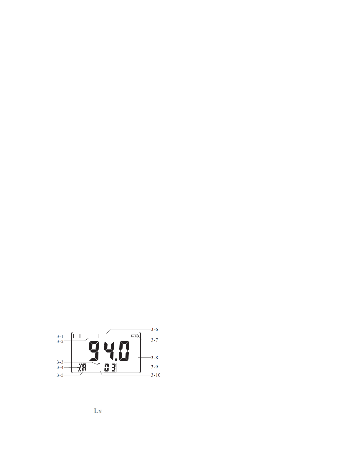
3-1 Calibration Mark
3-2 Time Weighting
3-3 Memory state
3-4 Mark for
3-5 Weighting Icon
3-6 Function Mark
Page 5
SU-BA-e-1713 5
3-7 Battery indicator
3-8 Max Hold
3-9 Number memorized
3-10 Browsing Icon
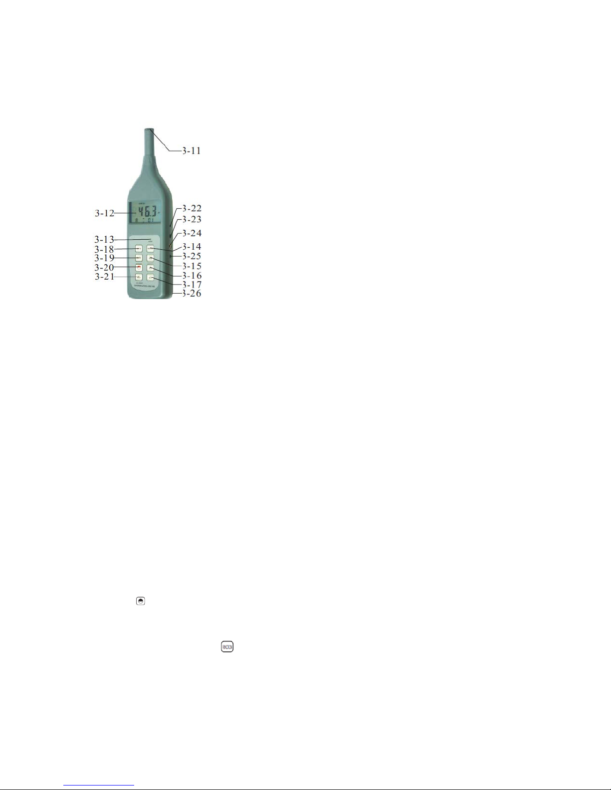
3-11 Microphone
3-12 Display
3-13 Alarm LED
3-14 Weighting key
3-15 Fast/Slow key
3-16 Up/Save key
3-17 Down/Read key
3-18 Function key
3-19 Max Hold key
3-20 Power key
3-21 Delete/Menu
3-22 Cal. Adjusting
3-23 Jack for RS 232C interface
3-24 Jack for output
3-25 Jack for AC
3-26 Battery compartment / cover
4 Measuring procedure
4.1 The key 3-20 has to be pressed and released to switch on the instrument.
4.2 It has to be checked whether the function selected is right. If not, it can be
changed by pressing the key 3-18.
The default setting is Lp, weighting A, Fast.
Lp – current sound pressure level
Leq – Equivalent Continuous A Sound pressure Level, i.e. arithmetically mean value
in a period of time set.
Page 6

6 SU-BA-e-1713
Ln – Statistic analysis, i.e. which percentage of all measurement values is larger than
or equal to the alarm value set by the user. For setting the alarm value, please see
chapter 7.
4.3 It has to be checked whether the weighting is right. If not, it can be changed by
pressing the key 3-14 to se l ect “A”, “C” or “Flat”.
With the “A” weighting selected, the frequency response of the device is similar to the
response of the human ear. “A” weighting is commonly used for environmental or
hearing conversation programs such as OSHA regulatory testing and noise
Ordinance law.
“C” weighting is a much flatter response and is suitable for the sound level analysis of
machines, engines etc.
Note: Weighting “A” will be automatically selected when measuring “Leq”.
4.4 The ke y 3-15 has to be used to select a Fast (125ms) or a Slow (1 second)
response time.
Fast has to be selected to capture noise peaks and noises that occur very quickly.
Slow response has to be selected to monitor a sound source that has a consistent
noise level or to average quickly changing levels. Slow response is selected for most
applications.
4.5 The reading is the highest one if the icon “max” appears on the display. The
reading is an instant value if “max” does not appear. This appearance is controlled by
pressing the key 3-19 during the process of measurement.
5 Storing and recalling readings
5.1 In state, the reading can be saved to the instrument together with measuring
conditions by pressing the key 3-16. Then the icon changes to state
automatically, while the number of memorized readings increases for 1.
5.2 No matter, in or in state, the memorized data can be browsed by pressing
the key 3-17. The browsing state is marked by `R` on the display.
In `R` state, all the readings memorized, can be recalled by pressing the or
key.
5.3 To delete the memorized value in memory, the browsing state has just to be
entered and the reading to be deleted has to be located by pressing the or
key.
Then the key 3-21 has to be pressed. If there appears “Err0” on the display, this
indicates that there is no more reading to delete.
Page 7

SU-BA-e-1713 7
6 How to set the „Leq“ time
Leq is used to access the rms average noise level over a preset period of time, often
the starting point of a noise assessment. To take the Leq measurement, the period
of time which has to be tested, must be selected. The longer the period of
measurement time, the m ore accurate the Leq reading will be. To set the period of
measurement time, the key 3-21 just has to be pressed for about 8 seconds until
“Leq” appears on the display. Then the key has to be released and the time has to be
selected among 10s, 1 min, 5 min, 10 min, 15 min, 30 min, 1 hour, 8 hours or 24
hours by pressing the Up (3-16) or Down (3-17) key.
To quit, any key except or key can be pressed.
7 How to set the alarm value
The alarm LED is on when the instant measurement value is bigger than or equal to
the alarm value set. The default setting value at the factory is 85dB. It can be
changed to any value between 30 and 130dB by the following steps:
The key 3-21 has to be pressed for about 5 seconds. It has to be released after
“AL” is shown on the display.
Then key or key have to be pressed to preset the alarm value as desired.
To quit, any key except or key can be pressed.
8 How to set the time of Auto-Power-off
The default setting for auto power off at the factory is 5 minutes, which means that
the device will auto power off 5 minutes from the time of the last key operation. This
can be changed by the user to any value between 1 to 9 minutes by the following
steps:
The key 3-21 has to be pressed for about 10 seconds and it can be released after
“AUTO” is shown on the display. Then the or key has to be pressed to preset
the time as desired. To stop the function of auto power off, time just has to be preset
to “0”. So the device will not be powered off automatically, it can only be shut down
manually in that case.
9 Calibration
The standard method to calibrate the instrument requires an external calibrator
(ASU-01) in addition to a small screw-driver.
9.1 Calibration of the device with ASU-01
a) The device has to be turned on.
b) It has to be preset in the “A” weighting mode
c) It also has to be preset the “SLOW” response mode
Page 8

8 SU-BA-e-1713
d) Then the microphone has to be placed into the calibrator. The calibrator has to
be switched ON.
e) The CAL potentiometer of the device has to be adjusted in the way that the
device’s display matches the output of the calibrator.
9.2 Calibration of the device by the inbuilt signal
The instrument has to be switched on to enter the calibration state. Then the key
3-18 has to be pressed until the icon “CAL” is to be seen on the display.
The screw-driver has to be used to adjust the CAL potentiometer of the device in the
way that the device shows 94dB.
10 General Considerations
- Wind blowing across the microphone increases the noise measurement. The
supplied foam cover has to be used to cover the microphone when applicable.
- The instrument may not be dismantled by inexperienced staff. There are no parts
inside which might serve the user.
11 Battery replacement
11.1 When the battery voltage is less than approx. 5V, it is necessary to replace
batteries.
11.2 The 4 x 1.5 V batteries have to be installed correctly into the case.
11.3 If the device is not going to be used f or an extended period, batteries have to be
removed.
12 Takeover of data memory into software
Important: First start the continuous data logging and then read out the stored data!
1. Connect the SU 130 to the PC (cable is optional available with software ATC 01).
2. Put the SU 130 into the Memory Read Mode (by pressing the READ-button).
3. Start the appropriate software.
Page 9
SU-BA-e-1713 9
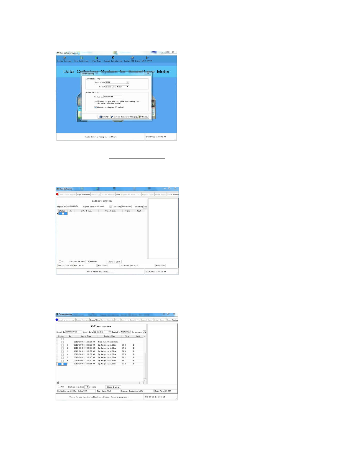
4. Select Port at System Settings at Interface Setup (e.g. COM1, USB4 or similar).
5. Select Product: Sound Level Meter.
6. Press Save (A) button and leave this window by Exit (X).
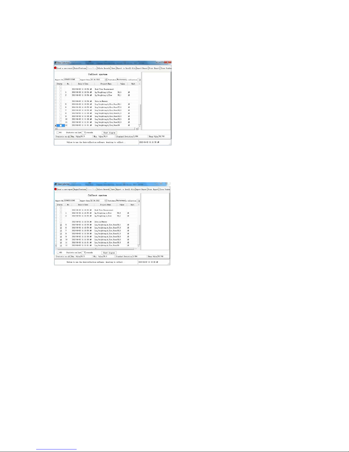
7. Open Data Collection.
8. Press Continue Button- press button on SU 130 (e.g. FAST/SLOW) – Data
acquisition Real Time star ts
Page 10
10 SU-BA-e-1713
9. Press READ- button on the SU 130- data in memory.
Readout of data starts and ends automatically with the last stored memory.
10. Select data (all which appears after “data in memory”)accordingly and continue
processing.
 Loading...