

Page 1
Sauter GmbH
Tieringerstr. 11-15
D-72336 Balingen
E-Mail: info@sauter.eu
Instruction Manual
MOBILE LEEB HARDNESS TESTER
Model: HMM
Table of contents
Caution
1. Summarize
1.1 Measuring Principle Scope
1.2 Hardness Value „L“
1.3 Main Features
1.4 Application Range
1.5 Technical Information
1.5.1 Display Unit
1.5.2 Impact Unit D
1.6 Overview Display Unit
1.7 Impact Device Assembling
2. Checking Supplied Accessories
3. Quick Start Guide
3.1 Cable Connection
3.2 Calibration
4. Operation Instructions
4.1 Display Unit
4.1.1 Keys
4.1.2 Measurement Mode
4.1.3 Setup
4.1.3.1 Material Group
4.1.3.2 Impact Direction
4.1.3.3 Scale
4.1.3.4 Browse
4.1.3.5 Adjusting Clock and Calendar
4.1.3.6 Calibration
4.2 The Format of Memory Data
4.3 Backlight
4.4 System Reset
4.5 Automatic Shutdown
5. Printing Data
5.1 Printer Link
5.2 Test Report Format
6. Hardness Test
6.1 Test Preparation
6.2 Sample Preparation
6.3 Test Steps
7. Troubles and Solutions
8. Maintenance and Service
8.1 Impact device Maintenance
8.2 Storage of Report
8.3 Normal Maintenance Procedures
APPENDIX 1 Daily Checking
Tel: +49-[0]7433- 9976-174
Fax: +49-[0]7433-9976-285
Internet: www. sauter.eu
HMM
APPENDIX 2 Factors affecting the Accuracy
APPENDIX 3 Measuring and Conversion Range
APPENDIX 4 Material Code
9. Declaration of Conformity
Caution
Please read this carefully first:
1. Only the special battery offered by our Company may be
used in the main body of the hardness tester. Improper
batteries might cause damages to the instrument, battery
leakage, even fire or explosion.
2. Any components of the instrument may not get
submerged in water or get exposed to rain, which could
cause a battery explosion and damage the main body.
3. Electrical shocks have to be avoided; the cabinet may
not be opened.
4. If the instrument hasn’t been used for a longer period, it
has to be stored in a cool and dry place.
1. Summarize
1.1 Measuring Principle Scope
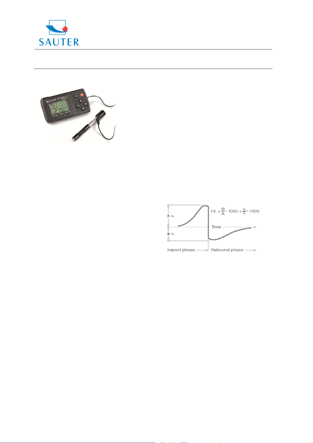
The measuring principle of HMO Hardness Tester is
physically a rather simple dynamic hardness test:
An impact body with a hard metal test tip is propelled by
spring force against the surface of the test piece. Surface
deformation takes place when the impact body hits the test
surface, which results in a loss of kinetic energy. This
energy loss is calculated by velocity measurements when
the impact body is at a precise distance from the surface
for both, the impact phase and the rebound phase, of the
test. The permanent magnet in the impact body generates
an induction voltage in the single coil of the impact device.
The voltage of the signal is proportional to the velocity of
the impact body. A signal processing by the electronics
provides the hardness reading for display and storage.
Simply said, harder materials produce higher rebound
velocities than less harder ones (higher L- value).
HMM Hardness Tester provides a direct hardness
measurement within any particular material group (i.e.
steel, aluminium etc.). It can be used as a final test result
without conversion. However, there are established
conversions to other hardness scales in this Hardness
Tester as a comfort for our customers. These conversions
to other scales (HRC, HRB, HB, HV, HSD etc.) are
programmed into the electronics and they can be shown
directly on the display as a test result. All data is stored in
the native L scale to prevent any possible errors with
multiple conversions.
HMM-BA-e-1111 1
Page 2

Sauter GmbH
Tieringerstr. 11-15
D-72336 Balingen
E-Mail: info@sauter.eu
Instruction Manual
1.2. The Hardness value “L”
This term was introduced 1978 into measuring technology
by Dr. Dietmar Leeb. It contains the quotient for the impact
body’s rebound and impact velocity, multiplied by 1000.
Harder materials produce higher rebound velocity than
less harder ones. With reference to a particular material
group (i.e. steel, aluminium etc.), the L value represents a
direct hardness measurement and is used as such.
Comparison curves with other standard statistic hardness
values have been established (Brinell, Vickers, Rockwell
C, B) for the most prevalent materials, enabling the
L values to be converted into the relevant values by these
procedures. With this hardness tester, such hardness
values can directly be displayed in the hardness scales
HRC, HRB, HB, HV, HSD and tensile strength (MPa).
1.3 Main features
- Highly accurate, ± 6 HL
- Automatic correction for impact direction
- Large, easy to read display with backlight
- User profiles for fast change of all settings
- Conversion to all common hardness scales
HRC, HRB, HB, HV, HSD and tensile strength
(MPa).
- Supplied by dry-cell, Ultra-low-power
- Easy calibration
- Conforms to the Standard ASTM A956-02
1.4 Application range
- Appropriate for all metals
- Ideal for production level testing
- Best suited for on- site testing of heavy, big or
already installed parts
- Handy for difficult to access or confined test
locations
- Automatic compensation for impact direction
- Excellent for material selection and acceptance
tests
- Easy to handle and accurate on curved test
surfaces (R> 10mm)
- Metal production & processing
- Automotive & transportation
- Aerospace & shipyard
- Testing services & laboratories
1.5 Technical information
1.5.1 Display unit
* HL Display range: 0 to 999 HLD
* Accuracy: ± 6 HL
* LCD: large LCD with backlight
* Resolution: 1 HL; 1 HV; 1 HB; 0,1 HRC;
0,1HRB; 1 HSD; 1 MPa
* Power: dry cell (3 x 1.5V AAA)
* Operating temperature: 0°C up to + 50°C
(32°F up to 122°F)
Tel: +49-[0]7433- 9976-174
Fax: +49-[0]7433-9976-285
Internet: www. sauter.eu
HMM
* Storage Temperature: -10°C up to + 60°C
(14°F up to 140°F)
* Humidity: 90 % max.
* Dimensions: 150mm x 80mm x 24mm
(5.9 x 3.1 x 0.9 inches)
* Weight: Approx. 200g (main body)
1.5.2 Impact unit D
Impact energy: 11 Nmm
Mass of the impact body: 5.5 g
Test tip diameter: 3 mm
Test tip material: tungsten carbide
Test tip hardness: ≥ 1600 HV
Impact length: 147 mm
Impact maximum diameter: 20 mm
Impact weight: 75 g
1.6 Overview Display Unit
Picture 1-1
1.7 Impact Device Assembling
1. Impact body
2. Support ring
3. Coil
4. Cable
5. Catch chuck
6. Loading tube
7. Release button
2. Checking supplied accessories
It should be checked that the following accessories are
supplied with your instrument
Picture 2-1
HMM-BA-e-1111 2
Page 3

Sauter GmbH
Tieringerstr. 11-15
D-72336 Balingen
E-Mail: info@sauter.eu
Instruction Manual
The items are supplied with the hardness tester. The
accessories available may vary from retailer to retailer,
depending on the country or service provider.
The purchased accessories only have to be used with
Polygon-authorised devices. The use with other devices
could cause problems and any repair costs wouldn’t be
covered by warranty.
3. Quick start guide
3.1 Connection
The signal cable has to be connected to the impact device
and the display unit.
Picture 3-1
HMM
Tel: +49-[0]7433- 9976-174
Fax: +49-[0]7433-9976-285
Internet: www. sauter.eu
b) In other mode, the “Back/Print” button has to be
pressed to complete setup and to save the parameters set.
Then it is returned to measurement mode.
4. “Browse” button: browse the memory data.
5. “Date/Time” button: adjustment of clock and calendar
6.
button: This button has to be pressed to delete
current data in measurement mode or browse mode.
7. button: It has to be pressed to setup the conversion
scale in measurement mode. In Date/Time setup mode
and in calibration mode, this button has to be pressed to
decrease the flickering bit. In browse mode,
to be pressed to display the next data.
8. button: It has to be pressed to setup the impact
direction in measurement mode. In Date/Time setup mode
and in calibration mode, this button has to be pressed to
button has
3.2 Calibration
The test block has been calibrated in accordance with the
dynamic hardness value L. The HMM Impact Hardness
Tester has to be calibrated by the test block before the first
use (APPENDIX 1)
4. Operating instructions
4.1 Display unit
4.1.1 Keys
Picture 4-1
2
increase the flickering bit. In browse mode,
to be pressed to display the previous data.
button: In measurement mode, it has to be pressed
9.
to select the material that will be impacted. In Date/Time
setup mode and in calibration mode, this button has to be
pressed to select the next bit.
4.1.2 Measurement Mode
HMM Hardness Tester has got a large LCD and an
abundance of information.
Picture 4-2
4.1.3 Setup
4.1.3.1 Material Group
In measurement mode,
select the material that will be impacted. Following material
list is shown on the back of the instrument:
button has to be pressed to
button has
“On/Off“ button: The instrument is turned on and
1.
off by pressing and holding the button.
2. Backlight button: The button has to be
pressed to turn on and off the LCD backlight.
3. “Back/Print” button:
a) In measurement mode, the “Back/Print” button has to
be pressed to erase the measured data. At the same time,
if the mini-printer is linked with the display unit, those data
will be printed out.
HMM-BA-e-1111 3
Page 4

Sauter GmbH
Tieringerstr. 11-15
D-72336 Balingen
E-Mail: info@sauter.eu
Instruction Manual
If button is pressed continuously, material changes
according to following sequence:
Note:
1. It is necessary to select the material classification. If
the type of material isn’t known, the related material
handbook will help.
2. If the material group is changed, the impact times
counter will be set to “0”.
3. Default setting: steel and cast steel.
4.1.3.2 Impact Direction
Ideal Leeb Hardness Testing is a downward straight
testing method. As a result of gravity, the test should be
amended when measuring other directions in order to
measure correct hardness values of materials. As long as
the impact direction is chosen correctly, impact direction is
automatically amended by the hardness tester.
There are five impact directions to chose:
In measurement mode, the
select the impact direction. It changes to following
sequence:
Note: Default setting is
4.1.3.3 Scale
HLD values can be automatically converted by HMM
Hardness Tester to other scales HRC,HRB, HB, HV, HSD
or tensile strength (MPa) according to a particular material
group (e.g. steel, aluminium etc.)
In measurement mode, the
convert all common hardness scales or tensile strength
(MPa). button has to be pressed continuously and the
scale changes according to following sequence:
Notes:
1. If the conversion is out of range, the conversion
value is indicated by “---“.
2. If the conversion is set from hardness scale to
tensile strength or the other way round, the material
group has to be reset.
2. Conversion value only supplies a general reference,
which results in some offset. Generally, comparative
tests are necessary to achieve precise conversion.
3. If the hardness scales are changed, the current
impact times counter will be cleared to “0”.
4. Standard setting for the conversion is “HRC”.
4.1.3.4 Browse
“Browse” button has to be pressed to browse stored data
and to display the first data group of the last nine test data,
button has to be pressed to
.
button has to be pressed to
HMM
Tel: +49-[0]7433- 9976-174
Fax: +49-[0]7433-9976-285
Internet: www. sauter.eu
including hardness value HLD, material, conversion
values, impact direction, date and time etc.
The
button has to be pressed to browse the next data
group.
previous data group. “Back/Print” button has to be
pressed to get back to measurement mode.
4.1.3.5 Adjusting Clock and Calendar
HMM Hardness Tester has got an inbuilt real-time clocksystem. Clock and calendar have to be adjusted if, i.e. the
dry cell has been reinstalled. The procedure is as follows:
The “Date/Time” button has to be pressed to enter clock
and calendar adjustment mode. If the “month” bit starts
flickering, the
and
The
flickering, the
and
The
flickering, the
and
The
flickering, the
and
The
starts flickering, the
increase and
to 59.
“Back/Print” button can be pressed every time if the
adjustment is completed and to return to measurement
mode.
4.1.3.6 Calibration
Calibration is used to calibrate the measured value (HLD)
of the hardness tester to decrease the measuring error as
far as possible. The procedure is as follows:
1) “Back/Print” button has to be pressed to clear the
testing times to “0”. It has to be impacted 5 times on the
test block to get an average value (some previous error
data can be deleted).
button has to be pressed to browse the
button has to be pressed to increase
button to decrease. Valid numbers are 1 to 12.
button has to be pressed and the “day” bit starts
button has to be pressed to increase
button to decrease. Valid numbers are 1 to 31.
button has to be pressed and the “year” bit starts
button has to be pressed to increase
button to decrease. Valid numbers are 00 to 99.
button has to be pressed and the “hour” bit starts
button has to be pressed to increase
button to decrease. Valid numbers are 00 to 23.
button has to be pressed and the “minute” bit
button has to be pressed to
button to decrease. Valid numbers are 00
HMM-BA-e-1111 4
Page 5

Sauter GmbH
Tieringerstr. 11-15
D-72336 Balingen
E-Mail: info@sauter.eu
Instruction Manual
2) “Date/Time” button has to be pressed about two
seconds to display the calibration mode. The HLD value
which is remarked on the test block has to be input by the
Tel: +49-[0]7433- 9976-174
Fax: +49-[0]7433-9976-285
Internet: www. sauter.eu
HMM
5.1 Printer Link
Picture 5-1
buttons
button again, the calibration is finished.
Note:
The hardness tester must be calibrated on the test
block before use.
The default impact direction is
4.2 The Format of Memory Data
The data group (such as test result, material and impact
direction) are automatically saved in memory after each
individual measurement. HMM Hardness Tester can store
9 sets of data. When measuring more than 9 times, the
last group of data will be stored in 9
one will be erased. The second group will be moved into
the 2nd position. Simultaneously, the position of other
groups of data will be moved into one lower position.
“Back/Print” button has to be pressed and held to end the
measurement and print out the memory data (if connected
to a printer). If printing is completed, the original data will
be erased automatically.
4.3 Backlight
LED backlight is used for poor light conditions. It can be
turned on and off by pressing the button. The present
situation will be saved while the instrument is powered off.
If there is no measurement and no key operation within 10
seconds, the backlight will be turned off automatically and
the display unit will be shut off in 3 minutes.
4.4 System Reset
If the display unit isn’t working properly or halts, the
“Reset” button has to be pressed by inserting a slender
rod into the reset hole on the backside of the display unit.
Then the display will be shutdown. To reboot the system,
the
4.5 Automatic Shutdown
If there is no measurement and no key operation within 3
minutes, the display unit will automatically be switched off
in order to save battery power. All the parameters will be
stored before.
5. Printing Data
HMM Hardness Tester can be linked with a microcomputer on infrared base to print out the hardness test
result report.
or or . By pressing the “Back/Print”
(see Appendix 1)
th
position and the first
button has to be pressed and held.
The infrared connection is used for display unit and printer:
The printer has to be moved to the left side of the display
unit. The printer infrared window has to be opposite to the
infrared window of the display unit. The micro-printer and
the display unit has to be turned on. Then the
“Back/Print” button has to be pressed to print out the test
report.
5.2 Test Report Format
A complete test report format is shown in picture 5-2.
Picture 5-2
Note: The date and time printed are the actual time,
which means the report end date and time.
6. Hardness Test
6.1 Test preparation
1) It has to be assured that the system connection is safe
and reliable.
2) The
power. It has to be inspected if every setting of the
display unit is correct, particularly material type and
impact direction. It may cause a great error if the setting
is not in accordance with the actual conditions.
button has to be pressed to switch on the
HMM-BA-e-1111 5
Page 6

Sauter GmbH
Tieringerstr. 11-15
D-72336 Balingen
E-Mail: info@sauter.eu
Instruction Manual
6.2 Sample Preparation
Inappropriate samples will cause great measurement
errors. Therefore, preparation and the necessary handling
should be done under original conditions of the sample.
Preparation of the sample and surface of test should be
coincident with the following basic requirements:
1) Cold processing and thermal processing of the impact
device during the process of sample surface preparation
should be avoided.
2) The surface of the sample should be plane, with a
metallic sheen, and not involve oxide layer or other stains.
3) Roughness of the test surface: Ra≤ 1.6
4) The sample has to be of sufficient quality and rigidity.
Otherwise displacements or shaking during the test might
happen. These could also lead to measurement errors.
A sample quality of ≥ 5 kg can be directly tested. If the
sample quality is 2~5 kg, it should be fixed before the test
by appropriate clamps. If the sample quality is 0.05~2 kg, it
should be coupled before the test; if it is < 0.05 kg, this
hardness tester is inappropriate to use.
Coupling method: The testing sample’s back should be
plane as well as the surface of the supporting object.
A little coupling substance (i.e. Industry Vaseline) has to
be filled between the two components. Then the two parts
have to be pressed together. If the weight of the supporting
object is more than 5 kg, it can be replaced by the test
block.
5) Samples should be thick enough with sufficient layered
surface. If the D-type of impact sensor is used, the
thickness of the sample should be less than 5 mm and the
surface absorption layer (surface- hardening layer) should
not be less than 0.8 mm. To perform accurate hardness
measurements, the best way is to remove this layer before
testing.
6) If the testing sample surface isn’t horizontal and flat, the
curvature radius of the testing and nearby surface should
be larger than 30 mm. An appropriate supporting ring has
to be selected and installed.
7) A sample should not be magnetic. The signal of the
impact sensor would be seriously affected, which might
cause inaccurate test results.
7. Test Steps
1) Loading:
The loading tube has to be slided forward to load the
impact device.
HMM
Tel: +49-[0]7433- 9976-174
Fax: +49-[0]7433-9976-285
Internet: www. sauter.eu
3) Measuring:
The trigger button has to be pressed to trigger the impact
device. The hardness value will be immediately displayed.
4) Reading the test result
The test result has to be read as shown in picture 6-4:
Sample Material: steel and cast iron
Impact direction: downwards
rd
Date: 3
Current hardness value: 786 HLD
The current measurement is the third point
Current mean value: 785 HLD
Conversions to HRC: 58.6 HRC
Mean value of HRC: 58.5 HRC
Repeating the above steps, tests in more points can be
carried out.
Note: Generally, each measurement location of sample
is conducted for five tests. The X (difference of max.
value and the min. value) values must be less than 15
HL. The distance between any two impact positions
should be ≥ 3mm; the distance between impact
position and the edge of the sample should also be
≥ 3mm.
7. Troubles and solutions
, December
2) Placing:
The impact device has to be placed and held on the
surface of the test piece at the desired test point. Impact
direction should be vertical with the surface being tested.
HMM-BA-e-1111 6
Page 7

Sauter GmbH
Tieringerstr. 11-15
D-72336 Balingen
E-Mail: info@sauter.eu
Instruction Manual
8. Maintenance and Service
8.1 Impact Device maintenance
After 1000- 2000 times use, the impact device and the
impact body should be cleaned with a nylon brush. The
screw of the supporting ring has to be turned off before the
catheter can be cleaned. Then the impact body has to be
taken out and it has to be rotated into the tube with the
nylon brush in anti-clockwise direction. The brush has to
be pulled out when touching the bottom. This procedure
has to be repeated several times. Then the impact body
has to be loaded and the supporting ring reinstalled. The
impact body should be released after use. The use of any
lubricant is banned.
9.2 Storage of the report
Printing paper is thermal paper and it should be preserved
to avoid heat and direct light. If the print records are
necessary to be kept in long-term conservation, they
should be copied and preserved in time.
8.3 Normal Maintenance procedures
If the error is larger than 12HLD by calibrating the
hardness tester, the steel ball or the impact body has to be
renewed. Those parts may be worn out and this may lead
to failure in operation.
In case if any other abnormal phenomena occur to the
Hardness Tester, it should not be either demolished or any
fixed assembly parts may not be adjusted. Instead, the
warranty card has to be completed and the Hardness
Tester has to be sent to our Maintenance department.
We will care for a prompt checking and if necessary, repair
of the device.
Appendix 1 Daily Checking
The test block is mainly used to calibrate the Hardness
Tester. The error and repeatability of it should be in the
scope defined in following table:
Note:
HLD is the mean value of 5 Leeb Hardness values
measured on the test block.
HLD is the value marked on the test block.
is the maximum value of 5 Leeb Hardness values
measured on the test block.
ist he minimum value of 5 Leeb Hardness values
measured on the test block.
HMM
Tel: +49-[0]7433- 9976-174
Fax: +49-[0]7433-9976-285
Internet: www. sauter.eu
Appendix 2 Factors affecting the Accuracy
Incorrect operation or improper testing conditions can
seriously affect the accuracy. The following factors are the
main accounts in lack of accuracy:
1) Roughness of sample surface
When the impact body impacts on the sample, a small pit
will arise on the surface of it. The less roughness, the less
consumption of impact energy is needed. According to
this, the roughness of the surface should be Ra≤ 1.6.
2) The shape of the sample surface
Leeb testing principle demands that the velocity of rebound
and impact are on the same line, because the impact body
is moving in a metal tube. Of course, hardness can also be
shown if the velocity of rebound and impact are not on the
same line. In this case, the impact body would collide with
the tube wall when it rebounds, which will affect the
velocity of rebound. This will cause an error on test
accuracy. If the radius of curvature of the sample surface
is smaller, a suitable variant supporting circle has to be
used. We can contribute to design and release those
supporting circles, if needed.
3) The weight of the sample
If the weight of the sample is more than or equal to 5 kg,
testing can be directly started. If it is less than 5 kg, the
sample needs a special charge. The supporting piece has
to be coupled by a coupling medium and pressed onto the
surface of the test piece. By doing this, better test results
will be achieved.
The area of the testing points should be free of vibrations
or shaking. If the weight of the sample is not enough,
supporting, coupling and compressing must be increased
to avoid jitter and sloshing. Shocks should be avoided.
4) The sample stability
Any effective tests need to minimize possible interference
from outside. This is very important for dynamic
measurements, such as Leeb Hardness testing.
Therefore, measurements are only allowed in a stable
hardness testing system.
Appendix 3 Measuring and Conversion Range
HMM-BA-e-1111 7
Page 8

Appendix 4 Material Code
Sauter GmbH
Tieringerstr. 11-15
D-72336 Balingen
E-Mail: info@sauter.eu
Instruction Manual
HMM
Tel: +49-[0]7433- 9976-174
Fax: +49-[0]7433-9976-285
Internet: www. sauter.eu
DESIGNED IN REGARD TO THESE STANDARDS:
• ASTM A956
• DIN 50156
9. Declaration of Conformity
HMM-BA-e-1111 8
 Loading...