

sauter FH-M 1 kN,FH-M2 kN,FH-M5 kN,FH-M10 kN,FH-M20 kN,FH-M50 kN,FH-M 100 kN Instruction Manual

Sauter GmbH
Ziegelei 1
D-72336 Balingen
E-Mail: info@kern-sohn.com
Tel.: +49-[0]7433- 9933-0
Fax: +49-[0]7433-9933-149
Internet: www.sauter.eu
Instruction Manual
Digital Force Gauge
SAUTER FH-M
V. 1.8
06/2017
GB
FH-M-BA-e-1718
PROFESSIONAL MEASURING
Sensor
Outside

2 FH-M-BA-e-1718
GB
SAUTER FH-M
V. 1.8 06/2017 Instruction Manual
Digital Force Gauge
Thank you for buying a SAUTER force gauge with an internal load cell. We hope you
are pleased with your high quality measuring instrument with its big functional range.
If you have any queries, wishes or helpful suggestions, do not hesitate to call our
service number.
Summarize:
1 Introduction .................................................................................................... 3
2 Scope of delivery ........................................................................................... 3
3 Working conditions ....................................................................................... 4
4 Specifications ................................................................................................ 4
5 Electrical Power Supp ly ................................................................................ 4
6 Operation ........................................................................................................ 5
6.1 Operation keys .......................................................................................................................... 5
7 Configuration of RS 232 interface ................................................................ 8
7.1 Output Protocol ........................................................................................................................ 9
8 Warnings ...................................................................................................... 10
9 Adjustment Procedure FH ........................................................................... 12
FH-M-BA-e-1718 3
1 Introduction
Annotation: Please read the remarks in this instruction manual carefully before the
first use, even if you are already experienced with our SAUTER measuring devices.
After receipt of your force gauge, please check the instrument, whether any transport
damages have occurred. Please check, whether the outer packaging, the plastic
housing or any other parts or even the instrument itself have been damaged. If any
damages are determined, please inform SAUTER immediately.
„Sensor outside“means, that the load cell is outside the housing, connected by a
cable with the display unit.
SAUTER offers suitable software and a wide range of accessories optionally. So you
are able to configure your measuring instrument more versatile. Please ask us at
SAUTER or your SAUTER reseller or just visit us on our website www.sauter.eu
2 Scope of delivery
- SAUTER FH-M, incl. rechargeable battery
- Carrying Case
- Charger
- 5 pieces M3 x 8 screws for fixation on all SAUTER Test Stands
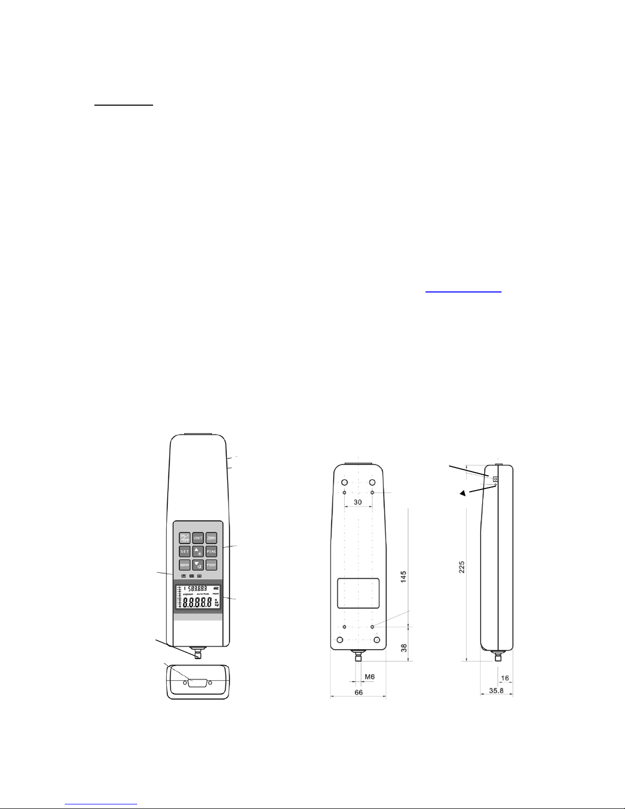
.
Power plug of
battery charger
Reset button
LCD-Display
Pilot lamp for
Limit value
indication
RS 232
Force sensor
M6 thread
Operation
keys
Reset- Taste
Dimensions in mm
Reset key
Adaptor
socket
4x M3 fixing
screws

4 FH-M-BA-e-1718
Max.charge
L x W x H
Thread type
Cable length
1 kN
76,2x50,8x19,0 mm
M12 x 1,75
Ca. 2,5m
2 kN
76,2x50,8x19,0 mm
M12 x 1,75
5 kN
76,2x50,8x28,2 mm
M12 x 1,75
10 kN
76,2x50,8x28,2 mm
M12 x 1,75
20 kN
76,2x50,8x28,2 mm
M12 x 1,75
50 kN
108x76,2x25,4 mm
M18 x 1,5
100 kN
177,8x125,0x50,8 mm
M30 x 2,0
Important annotation:
By pressing the RESET key (on the right side of housing, see illustration on page 3),
individual settings and memorised values can be re-set or erased, in example for a
new start of the instrument after an operating error.
You will find the description of mounting all force gauges on SAUTER Test
stands in the instruction manuals of the correspondent test stands.
3 Working conditions
10°C up to 30°C / 15% up to 80% humidity
4 Specifications
- Measurement uncertainty: ± 0,5 % of Max (measurement range)
- Measurement frequen c y: 2.000 Hz
- Weight: 640 g (display unit without external load cell)
5 Electrical Power Supply
Either by rechargeable battery or current power supply
Current power supply:
- Connection by power adapter
- Rechargeable batteries are charged simultaneously
Rechargeable battery pack for mobile applications:
External load cell
connected by a cable
with the display unit,
See photo on the
cover sheet
 Loading...