

Page 1

Heating controller
User's Manual
EQJW 125
7001029003 T8
R
7001029003 T8 Sauter Components
Page 2

7001029003 T8 Sauter Components
Page 3

- 3 -
Table of contents
1 General information.............................................................................................................................................................. 5
1.1 Introduction.................................................................................................................................................................... 5
1.2 Safety information.......................................................................................................................................................... 5
1.3 Key to the Operating Instructions .................................................................................................................................. 5
1.4 Abbreviations.................................................................................................................................................................5
2 Description of the controls .................................................................................................................................................. 6
2.1 Front view of the EQJW 125.......................................................................................................................................... 6
2.2 Rotary switch .................................................................................................................................................................6
2.3 Input knob...................................................................................................................................................................... 7
2.4 ESC button .................................................................................................................................................................... 7
2.5 Display........................................................................................................................................................................... 7
3 Commissioning..................................................................................................................................................................... 8
3.1 Operating the device for the first time............................................................................................................................ 8
3.1.1 Setting the time...................................................................................................................................................... 8
3.1.2 Setting the date...................................................................................................................................................... 8
3.2 Manual mode.................................................................................................................................................................9
3.2.1 Access to manual mode ........................................................................................................................................9
3.2.2 Set valve position................................................................................................................................................... 9
3.2.3 Set status of pump (on/off) for manual operation ..................................................................................................9
3.2.4 Ending manual mode........................................................................................................................................... 10
3.2.5 Checking measured values in manual mode....................................................................................................... 10
3.3 SERVice mode ............................................................................................................................................................ 10
3.3.1 Accessing SERVice mode ................................................................................................................................... 10
3.3.2 Viewing SERVice parameters.............................................................................................................................. 11
3.3.3 Changing SERVice parameters ........................................................................................................................... 11
3.3.4 List of SERVice parameters................................................................................................................................. 12
3.3.5 Explanations of SERVice parameters.................................................................................................................. 13
3.4 Communication mode.................................................................................................................................................. 16
3.4.1 Access to communication mode .......................................................................................................................... 16
3.4.2 Viewing the communication parameters.............................................................................................................. 16
3.4.3 Changing communication parameters ................................................................................................................. 17
3.4.4 List of communication parameters....................................................................................................................... 18
3.4.5 Explanations about individual communication parameters.................................................................................. 19
4 Operation............................................................................................................................................................................. 21
4.1 Operating modes ......................................................................................................................................................... 21
4.1.1 Display in automatic mode................................................................................................................................... 22
4.1.2 Display when OFF mode, reduced mode and normal mode are set ................................................................... 23
4.2 Entering the setpoint temperature in normal mode...................................................................................................... 24
4.3 Entering the setpoint temperature in reduced mode.................................................................................................... 24
4.4 Weekly switching programme...................................................................................................................................... 25
4.4.1 Calling up the weekly switching programme........................................................................................................ 25
4.4.2 Viewing switching commands .............................................................................................................................. 25
4.4.3 Entering a switching command............................................................................................................................ 25
4.4.4 Changing and deleting a switching command ..................................................................................................... 26
4.5 Calendar switching programme................................................................................................................................... 26
4.5.1 Calling up the calendar switching programme..................................................................................................... 26
4.5.2 Viewing switching commands .............................................................................................................................. 27
4.5.3 Entering a switching command............................................................................................................................ 27
4.5.4 Changing and deleting a switching command ..................................................................................................... 27
4.6 Temporary temperature change .................................................................................................................................. 28
7001029003 T8 Sauter Components
Page 4

- 4 -
5 Communication functions ................................................................................................................................................. 29
5.1 Device bus .................................................................................................................................................................. 29
5.1.1 Assigning addresses ........................................................................................................................................... 29
5.1.2 EDB 100 room operating unit .............................................................................................................................. 29
5.1.3 Sending and receiving outdoor temperatures ..................................................................................................... 29
5.1.4 Requesting and processing a heat requirement.................................................................................................. 29
5.1.5 Synchronising the time........................................................................................................................................ 29
5.2 Modbus communication .............................................................................................................................................. 30
5.2.1 Modbus bus wiring .............................................................................................................................................. 31
5.2.2 Modbus data points (holding register) ................................................................................................................. 31
5.2.3 Modbus data points (Coils).................................................................................................................................. 32
5.3 Modem operation ........................................................................................................................................................ 33
5.3.1 Modbus operation via modem ............................................................................................................................. 33
5.3.2 Sending SMS if there is a fault on the plant ........................................................................................................ 33
5.3.3 Displays for modem operation............................................................................................................................. 33
6 Faults................................................................................................................................................................................... 34
6.1 Displaying faults .......................................................................................................................................................... 34
6.1.1 Error list ............................................................................................................................................................... 34
6.1.2 Device status....................................................................................................................................................... 34
6.2 Reset functions ........................................................................................................................................................... 34
6.3 Actions to deal with faulty temperature readings ........................................................................................................ 34
7 Application.......................................................................................................................................................................... 35
7.1 Plant schematic........................................................................................................................................................... 35
7.2 General information..................................................................................................................................................... 35
8 Economy tips...................................................................................................................................................................... 36
9 Resistance values for the Ni1000 sensors....................................................................................................................... 36
10 Accessories ........................................................................................................................................................................ 37
11 Wiring diagram ................................................................................................................................................................... 37
12 Dimension drawing ............................................................................................................................................................ 37
13 Technical data .................................................................................................................................................................... 38
13.1 Overview of technical data .......................................................................................................................................... 38
13.2 Overview of main functions ......................................................................................................................................... 39
14 Overview of controller settings......................................................................................................................................... 40
14.1 List of SERVice parameters ........................................................................................................................................ 40
14.2 List of communication parameters .............................................................................................................................. 40
14.3 Weekly switching programme ..................................................................................................................................... 41
14.4 Calendar switching programme................................................................................................................................... 41
15 Index of key words ............................................................................................................................................................. 42
7001029003 T8 Sauter Components
Page 5

- 5 -
1 General information
1.1 Introduction
Thank you for purchasing a heating controller from Sauter. The equithermEQJW 125 is a quality product from one of the leading
manufacturers of controls products for heating, ventilation and air-conditioning.
The equitherm
temperature. In automatic mode, it uses switching commands from the weekly time-switch (weekly switching programme) to
reduce the room temperature during the night (reduced mode) and switches to the normal temperature during the day. It is
suitable for all types of building. A fixed basic programme (ex-works setting) ensures simple commissioning. If any adaptation
to the heating plant is required, this is carried out using the SERVice parameters. An automatic change-over between summer
and winter time relieves residents of the need to correct the time twice a year. The equitherm
protective functions such as the anti-frost function and the anti-jamming function for the pump. Additional functions such as the
automatic switch-off have been implemented. This ensures optimum convenience with the minimum use of energy for every
plant.
Analogue or digital room remote-control units can be connected to the EQJW 125, enabling easy remote operation of the
controller from the living room.
The communication interface allows the interconnection of several controllers, a connection to a control station and alarms on
a mobile telephone via SMS messages.
1.2 Safety information
EQJW 125 is a compact weather-compensating heating controller with switched outputs to control the flow
EQJW 125 contains various
Particular care is required in order to prevent injuries, fire damage and damage to equipment. After the device has
been installed by a specialist according to the Installation Instructions (MV505870) which are enclosed with it,
please read these instructions on how to operate it. Local regulations must be followed during the installation. The
controller is not a safety-relevant component. The anti-frost and anti-overheating functions and the limitation of the
flow temperature do not replace the corresponding safety devices.
1.3 Key to the Operating Instructions
... means see Section ...
... means ex-works setting for the EQJW 125 (e.g.
control values, switching times etc. specified by the manufacturer)
The Operating Instructions give a step-by-step explanation of the individual functions of the device, with the help of the
following symbols:
... means flashing 'PROG' indicator on the display
... means the '09:00' indicator on the display (not flashing)
....
... means key to be pressed ....
1.4 Abbreviations
CO = communication T
SE = SERVice T
SP = SERVice parameter T
T
T
T
T
T
T
= outdoor temperature T
A
= minimum limit for the setpoint for T
Fsmin
= flow temperature T
F
= setpoint for the flow temperature T
FS
= actual value for the flow temperature X
Fi
= maximum limit for the setpoint for T
Fsmax
F
F
T
X
= room temperature
R
= actual value for the room temperature
Ri
= maximum limit for the adjusting range for T
Rmax
= minimum limit for the adjusting range for T
Rmin
= setpoint for the room temperature
RS
= heating limit
S/W
Y = valve run-time
= proportional band
P
= setpoint
s
RS
RS
7001029003 T8 Sauter Components
Page 6
- 6 -
2 Description of the controls
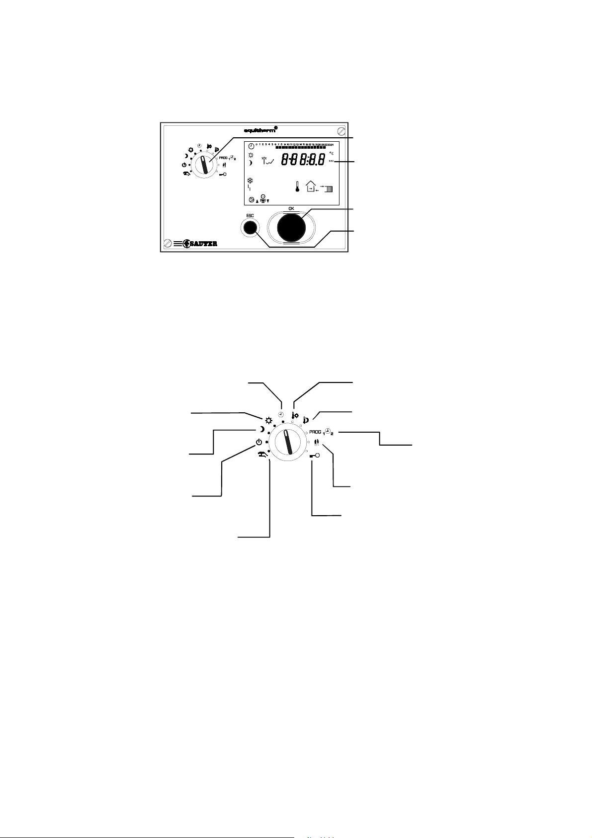
2.1 Front view of the EQJW 125
EQJW125
The device has a rotary switch with 10 positions, an input knob and a button.
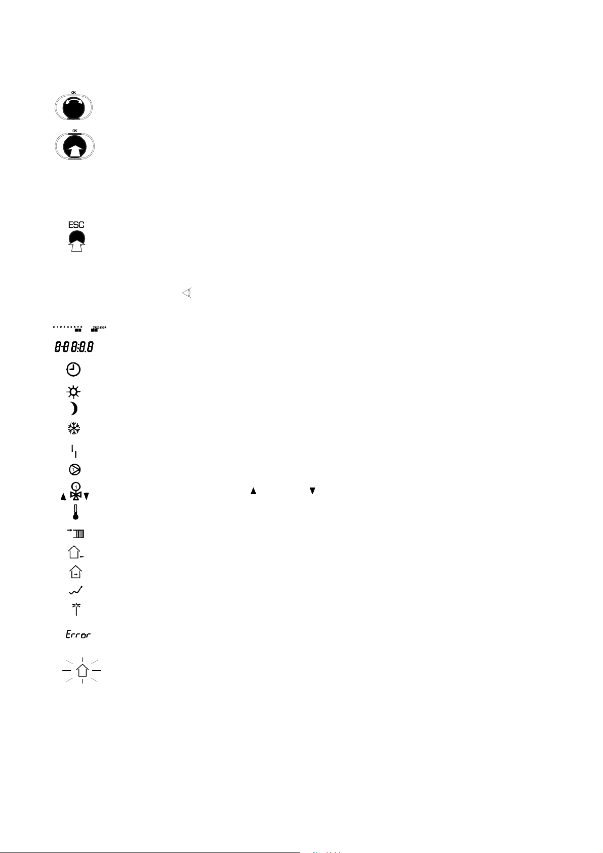
2.2 Rotary switch
The meanings of the switch positions are as follows:
Operating modes:
Automatic mode according
to switching programme
Controller is
continuously in
normal mode*)
Controller is
continuously in
reduced mode
Controller is
continuously in
back-up mode**)
Access to manual mode
Rotary switch
Display
Input knob
ESC button
Inputs:
Setpoint adjustment
Normal mode
Setpoint adjustment
Reduced mode
Enter
weekly and
calendar programme
Temperature change
with (without) time limit
Access to SERVice and
communication level
*) Normal mode corresponds to nominal mode as per EN12098-1.
**) Back-up mode means that the heating is switched off. The anti-frost function is active.
7001029003 T8 Sauter Components
Page 7
2.3 Input knob
With the help of the input knob, you can scroll through menus or select and change values.
Unless explicitly stated otherwise, you can scroll through menus or change values in the form of a circular
structure. There is no 'limit stop' for adjusting values or scrolling.
The input knob has a button function, i.e. it can be pushed. This movement is used to select the parameter
that is currently displayed so as to make a change, or to confirm a flashing value, or to access a subordinate
menu level.
2.4 ESC button
You can use the ESC button to cancel procedures or to return from a subordinate menu item to the next level up.
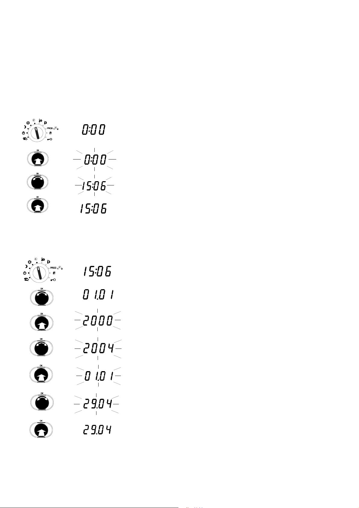
2.5 Display
The device has an LC-Display ( 2.1 ) which can show various items of information at the same time. The next illustration
shows what the symbols mean:
- 7 -
...
...
Times for normal mode on the current day
Time, date, setpoints, actual values, etc.
Automatic mode according to the weekly and calendar switching program; flashing: (un)limited temp. change
Controller is operating in normal mode
Controller is operating in reduced mode
Controller is operating in back-up mode; flashing: anti-frost function is active
An error has occurred (faulty sensor)
Heating medium pump is switched on
Final control element is open (
Display of setpoint temperature; flashing: display of actual temperature
Display of flow temperature
Display of outdoor temperature
Display of room temperature
Controller is in summer mode
Calendar switching programme is currently active
) or closed ( )
An error has occurred (see Section 6)
Floor-drying (operational heating) is active
7001029003 T8 Sauter Components
Page 8
- 8 -
3 Commissioning
3.1 Operating the device for the first time
When you operate the equitherm EQJW 125 for the first time, you have to set the date and time. The controller is then
basically ready to use. However, depending on the particular application, it may be necessary to change more settings after
this.
3.1.1 Setting the time
Set the rotary switch to automatic mode;
the time is shown
Press the input knob;
the time flashes ...
Turn the input knob;
the time is set
3.1.2 Setting the date
Press the input knob again;
the new time is confirmed
Set the rotary switch to automatic mode;
the time is shown
Turn the input knob until the date is shown
(day/month and year are shown alternately)
Press the input knob;
the number of the year flashes ...
Turn the input knob;
year is changed
Press the input knob;
year is confirmed and day/month are shown
Turn the input knob;
the date is changed
Push the input knob;
new date is confirmed
7001029003 T8 Sauter Components
Page 9
- 9 -
3.2 Manual mode
In manual mode, you can control the plant by hand during installation or in case of a fault. No regulating takes place in manual
mode. The pump is switched on or off. The valve is opened and closed according to the specified values. Before you can work
in manual mode, this mode has to be enabled in SERVice mode (see Section 3.3).
When the switch position is selected, the mixer initially retains its current position and the heating circulation pump is switched
on. The current statuses of the controller outputs (pump on, mixer open, mixer closed) are shown on the lower margin of the
display, as usual (see Section 2).
3.2.1 Access to manual mode
Set the rotary switch to manual mode
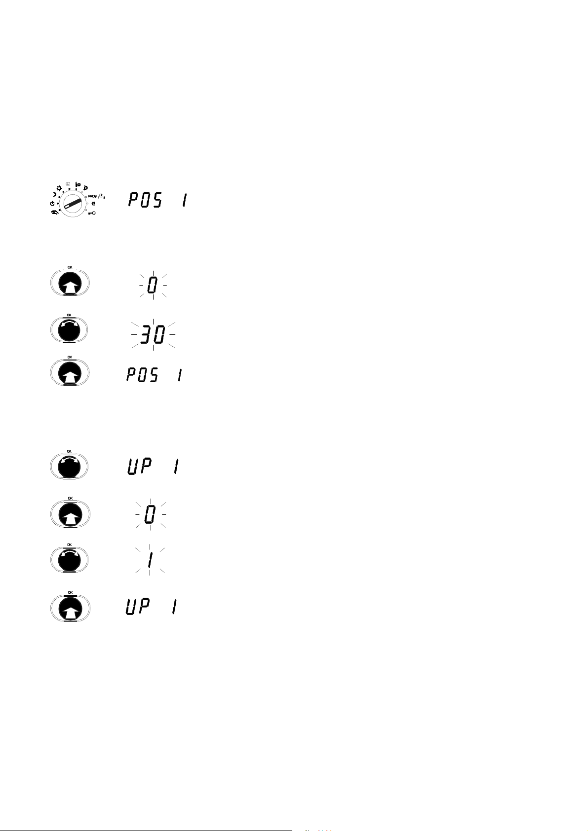
3.2.2 Set valve position
Push the input knob;
i.e. select the 'Open final control element' option on the menu
Turn the input knob;
value for percentage opening of the final control element
Push the input knob;
confirm the value
3.2.3 Set status of pump (on/off) for manual operation
Turn the input knob;
select the 'Heating medium pump output' option on the menu
Push the input knob;
select the menu option
Turn the input knob;
specify pump output
(0= pump off, 1=pump on)
Push the input knob;
the setting is accepted
7001029003 T8 Sauter Components
Page 10
- 10 -
3.2.4 Ending manual mode
Manual mode is ended as soon as you turn the rotary switch to another position.
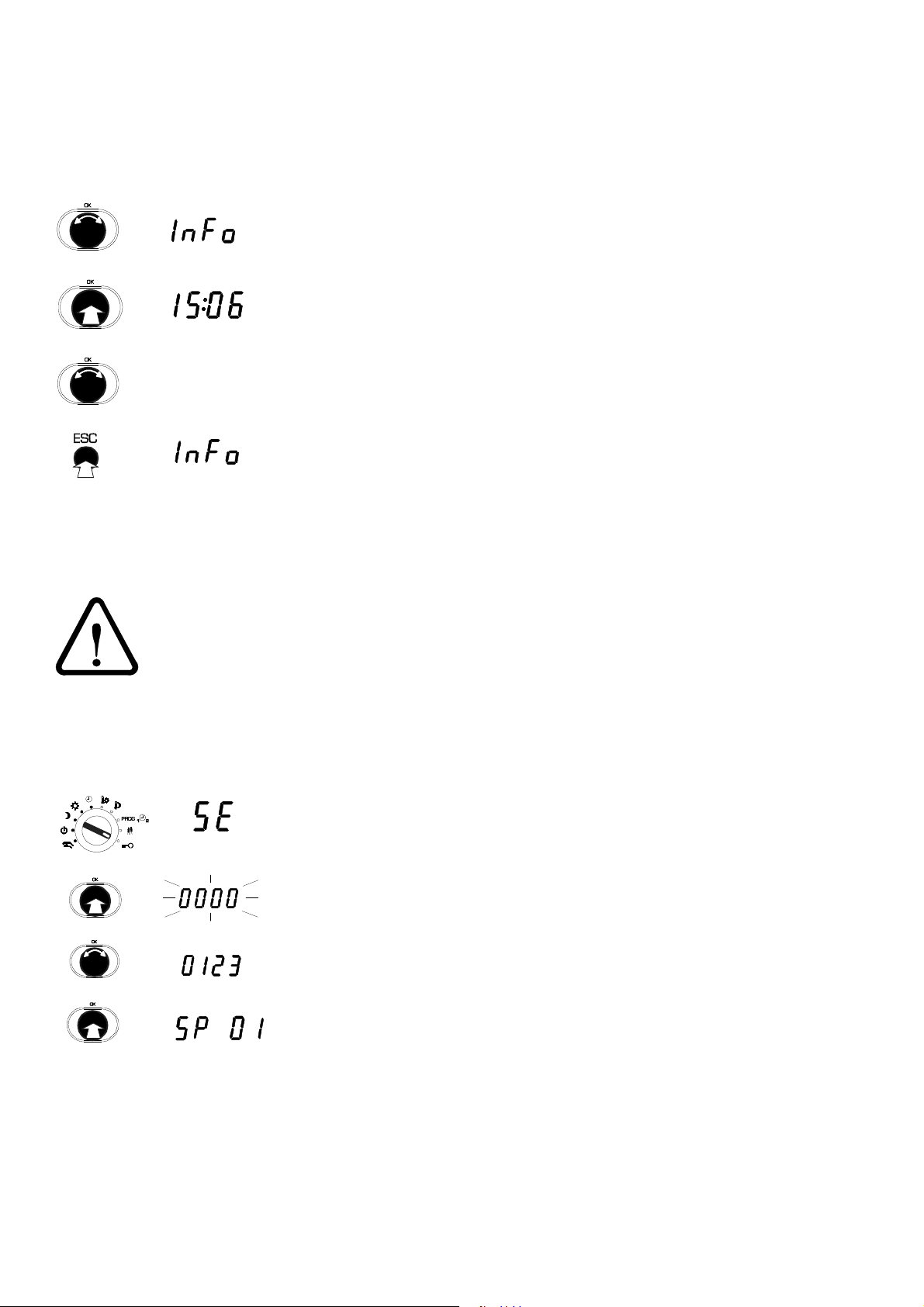
3.2.5 Checking measured values in manual mode
Turn the input knob until the 'INFO' menu option appears on the display
Push the input knob;
select the 'INFO' menu option
...
Turn the input knob; the individual values are shown. The display loop is the
same as for the 'automatic mode' switch position
Push the 'ESC' button;
exit from the 'INFO' menu option
3.3 SERVice mode
In SERVice mode, a specialist can adapt the basic settings of the EQJW 125 to the plant so as to meet specific requirements.
On this subject, also note the Installation Instructions (MV 505870) enclosed with the EQJW 125.
SERVice mode must only be enabled by a specialist. Incorrect parameterisation (setting) of the heating
controller can cause major faults on the plant or injuries to people and damage to the plant.
Some of the parameters cannot be changed - they can only be viewed (version number, status information).
3.3.1 Accessing SERVice mode
Set the rotary switch to the Service position
Push the input knob
Turn the input knob,
display the code
Push the input knob;
the first SERVice parameter is shown
7001029003 T8 Sauter Components
Page 11

3.3.2 Viewing SERVice parameters
Turn the input knob;
Select the SERVice parameter that you want
Push the input knob;
the value for the parameter is shown
To leave the value unchanged,
exit from the display by pushing ESC
3.3.3 Changing SERVice parameters
Turn the input knob;
Select the SERVice parameter that you want
Push the input knob;
the value for the parameter is shown
- 11 -
Turn the input knob;
the value for the parameter is changed
Push the input knob;
the new value is confirmed
Push the ESC button to cancel the procedure. The value is not accepted unless it has already been confirmed.
7001029003 T8 Sauter Components
Page 12

- 12 -
3.3.4 List of SERVice parameters
Parameter Description Range
SP01 Software version Y.XX (read only)
SP02 0 Device status (error coding, read only) 0…1031 1
SP04 0 Software reset 0…3 1
0 = no reset
1 = default SERVice + communication parameters
2 = default switching commands
3 = default SERVice + communication parameters +
switching commands
SP05 0 Manual mode 0...1 1
0 = manual mode not enabled
1 = manual mode enabled
SP06 3 Output signal / control model 2...3 1
2 = PWM output
3 = 3-pt output
SP07 2 Room temperature detection 0...3 1
0 = no room temperature detection
1 = connection of NI1000 room sensor
2 = Connection for EGS 52/15 or EGT 333 with room sensor
3 = Connection for EGS 52/15 or EGT 333 w/o room sensor
SP08 0 Room temperature connection 0...1 1
0 = not enabled
1 = enabled
SP09 20 Scanning time for room temperature if connected, in minutes 1...20 1
SP10 0 Room temperature correction in K –6.0...6.0 0.1
SP11 0 Outdoor temperature correction in K –9.9...9.9 0.1
SP12 40 Proportional band PI controller in K 2...100 1K
SP13 240 Reset time PI controller in sec 5...1000 5
SP14 120 Valve run-time in sec 30...960 15
SP15 5 Minimum limit for flow temperature in °C 5...100 1K
SP16 75 Maximum limit for flow temperature in °C 20...130 1K
SP17 1.4 Slope of heating curve 0.0...5.0 0.1
SP18 15 Heating limit / [°C] 0...39 1
SP19 –16 Design temperature / [°C] –50...0 1
SP20 1 Anti-frost function 0...1 1
0 = not enabled
1 = enabled
SP21 0 Anti-jamming function for the pump 0...1 1
0 = not enabled
1 = enabled
SP22 0 Calendar programme 0...1 1
0 = not enabled
1 = enabled
SP23 25.10 Summer/winter time change-over 01.01...31.12
SP24 25.03 Winter/summer time change-over 01.01...31.12
P23 = P24 means no summer/
winter time change-over
SP60 0 Floor drying 0;7d;8;9
0 = not enabled
7d = enabled
8 = malfunction
9 = successfully completed
Step
value
0,7d;8;9
7001029003 T8 Sauter Components
Page 13

- 13 -
3.3.5 Explanations of SERVice parameters
SP01 Show software version
The number of the controller's software version is displayed.
SP02 Display device status
SERVice parameter 2 is used to read the device status of the EQJW 125. A value of 0 means that the EQJW 125 is operating
without any faults. The coding for faults is shown in Section 6.1.1. Once the fault has been rectified, the value for the SERVice
parameter is reset automatically.
Remark: this coded description of errors is primarily used for fault signalling via bus, modem or SMS. You can easily read
faults directly on the controller in the ERROR display (Section 6.1).
SP04 Software reset
Switching commands and / or SERVice/communication parameters are reset to the ex-works setting. To do this, the value of
the SERVice parameter has to be changed and confirmed. The EQJW 125 then performs the relevant reset and assigns value
0 to the parameter.
SP05 Manual mode
SERVice parameter P05 is used to disable or enable manual mode. If the value of the parameter is 0, manual mode is disabled.
SP06 Output signal / control model
This parameter is used to select the control signal for the final control element. You can choose between a signal for 3-point
control and a PWM output (Pulse – Pause) with a fixed period of 64 seconds. If the PWM signal is used, the signal is available
on terminal 4.
Caution: when the PWM output is used, the functions for limitation of the flow temperature are no longer effective.
SP07 Room temperature detection
Various types of room temperature sensor can be connected:-
0 = no room temperature detection
1 = connection of room sensor NI1000
2 = Connection for EGS 52/15 or EGT 333 with room sensor
3 = Connection for EGS 52/15 or EGT 333 without room sensor
It is possible to switch over the operating mode of the controller from a room user panel. This can also be done from a control
station via Modbus. In the event of contradictory commands, the following priority applies:
direct settings on the controller take precedence over the room user panel and Modbus. Settings on the room control device
take precedence over Modbus commands.
SP08 Room temperature connection
A room temperature sensor (resistance sensor Ni1000 or device bus) is a requirement for this function. The flow temperature
is changed, in divergence from the setpoint according to the heating characteristic, if the room temperature in the reference
room diverges from the room setpoint. The change in the flow temperature is limited to a maximum of ± 30K.
SP09 Scanning time for room temperature if connected
When the room temperature connection is active, this SERVice parameter can be used to set a period within which the flow
setpoint may be altered once only. A higher value is better for unresponsive buildings and heating systems than for light
construction types with responsive heating systems. This period should not be too short, otherwise the control system may
hunt. The algorithm prevents hunting by changing the flow setpoint more quickly (at a rate of ±2 K within a scanning period)
when the deviation of the room temperature is diminishing than when it is increasing (at a rate of±1 K within a scanning
period). If the deviation of the room temperature is less than 0.25 K, the flow setpoint is not altered. In most cases, the factory
setting (20 minutes) provides satisfactory results for residential buildings.
: Open windows or other cooling or heating loads may have an effect on controllability. If these influences suddenly cease,
N.B.
the room temperature may briefly be exceeded or undercut in the opposite direction.
SP10 Correction of room temperature
The measured value for the room temperature is adjusted with the help of this parameter. The value that is entered is added to
the measured value for the room temperature.
SP11 Correction of outdoor temperature
The measured value for the outdoor temperature is adjusted with the help of this parameter. The value that is entered is added
to the measured value for the outdoor temperature.
7001029003 T8 Sauter Components
Page 14

- 14 -
SP12 Proportional band
SERVice parameter 12 sets the proportional band (X
) of the PI control for the flow temperature in K.
P
SP13 Integral action time
SERVice parameter 13 determines the integral action time (TN) of the PI control for the flow temperature in seconds.
SP14 Valve run-time
Valves with a motorised actuator need a certain time (known as the valve run-time) to open or close completely. This SERVice
parameter is used to set the equitherm
EQJW 125 to the run-time for the valve drive that is being used. Optimal control
quality and various protective functions are only ensured if the valve run-time is set correctly.
SP15, SP16 Minimum and maximum limits for flow temperature
The setpoint flow temperature can be limited. The value of SERVice parameter SP15 sets the lower limit in this case, and the
value of SERVice parameter SP16 sets the upper limit. Parameters SP15 and SP16 specify a maximum and minimum flow
temperature.
SP17 Slope of heating characteristic
The flow temperature is controlled according to the outdoor temperature. The heating characteristic in the controller
determines the setpoint for the flow temperature in relation to a given outdoor temperature.
3,0 3,5 4,0
2,0
1,8
1,6
1,4
1,2
1,0
0,8
0,6
0,4
-20 -15 -10 -5 0510 15
2,5
SP17: Slope
[°C]
Outdoor temperature
1
-
0
100
[°C]
Guideline for the slope
90
of the heating characteristic:
80
70
1.4 for hot water
60
50
40
30
I
T
5
-
radiator heaters
)
(
Flow temperature
1.0 for low temperature heaters
]
0.6 for floor heaters
C
°
[
5
SP18 Heating limit
If the averaged outdoor temperature is higher than the heating limit, heating operation is stopped. As soon as the value falls
back below the heating limit, heating operation is resumed. To avoid frequent status changes, a hysteresis of 1K is taken into
account in both cases.
The outdoor temperature required for control purposes can either be measured with an outdoor temperature sensor or can be
received via a connected device bus. The measured outdoor temperature is averaged over 21 hours for the heating limit
function in order to reduce the influence of brief fluctuations.
SP19 Design temperature
If the current outdoor temperature is less than the design temperature, the EQJW 125 heating controller will no longer switch
to reduced operating mode but will remain in normal operating mode.
SP20 Anti-frost
The anti-frost function becomes active if the outdoor temperature falls below the anti-frost limit (= +3°C). If the outdoor
temperature rises above 4°C again, the function is ended. The flashing
symbol indicates that the anti-frost function is active.
It forces the circulating pump for the heating circuit to switch on. The setpoint for the flow temperature of the heating circuit is
set at +10°C unless it is already higher. In addition, regardless of the outdoor temperature, temperature TF (flow sensor) is
monitored to a limit value of 5°C. If SP20=0, the function can be disabled and the controller will no longer offer an anti-frost
function in this case!
SP21 Anti-jamming function for the pump
If this function is enabled, a daily check is carried out (at 0.00 hours) to determine whether the pump was operated in the last
24 hours. If not, it is operated for one minute to prevent jamming.
7001029003 T8 Sauter Components
Page 15

- 15 -
SP22 Calendar switching programme
This SERVice parameter is used to either enable or disable the calendar switching programme. Only when the calendar
switching programme is enabled can calendar switching commands be entered. If the parameter has a value of 1, the calendar
switching programme is enabled; if it has a value of 0, it is disabled. The factory setting for this parameter is 1.
SP23, P24 Summer/winter or winter/summer time-change
Thanks to the calendar time-switch integrated into the equitherm
summer/winter time-change are carried out automatically. The date for the change-over is specified by the value for SERVice
parameters SP23 and SP24. A value of 16.2 corresponds to 16
EQJW 125, the winter/summer time-change and the
th
February. If the date entered is a Sunday, the change-over takes
place on the same day. Otherwise, the change-over is performed on the following Sunday. For the summer/winter time-change,
the time is put back from 03:00 hours to 02:00 hours. The winter/summer time-change takes place at 02:00 hours.
The time is put forward to 3:00 hours. If SERVice parameters SP23 and SP24 have the same values, no summer/winter timechange is performed.
SP60 Floor-drying function
EN 1264, Part 4 describes how anhydrite cement floors should be treated during operational heating before the floor covering
is laid. This entails, first of all, maintaining an inlet temperature of 25°C for 3 days. Thereafter, the maximum inlet temperature
should be maintained for four days. This function has been included on the EQJW 125; it can be activated via SERVice
parameter SP60, which should be assigned with a value of 7d.
The EQJW 125 should be adapted to the installation before the floor-drying function is activated. In particular,
SERVice parameter 16 (maximum flow temperature) should be set first of all to a value that is suitable for the floor
and the heating circuit.
When the floor-drying function is active, the 'house' symbol flashes. An additional value appears in the display, showing the
remaining time.
When the floor-drying function has been successfully completed, parameter SP60 is given a value of 9. This value can be read
only; it can be changed to only 0 or 1. If the floor-drying function was interrupted (due to a sensor failure or high control
deviation over a long period etc.), 8 is displayed (instead of 9) as the error message. After the floor-drying has finished, the
EQJW 125 runs in accordance with the switch position and the switching commands. The floor-drying function can be aborted
by setting parameter SP60 to 0. In the event of a power failure, the floor-drying function is interrupted. When power is restored,
the floor-drying function automatically re-starts from the beginning. The floor-drying function is aborted if the flow sensor
malfunctions.
7001029003 T8 Sauter Components
Page 16

- 16 -
3.4 Communication mode
In communication mode, a specialist can enable and configure the communication functions of the EQJW 125.
Communication mode must only be enabled by a specialist. Incorrect parameterisation (setting) of the heating
controller can cause major faults or damage to the plant.
3.4.1 Access to communication mode
Set rotary switch to Service position
Turn the input knob,
select 'CO' (COmmunication)
Push the input knob
Turn the input knob,
show the code
Push the input knob;
the first communication parameter is shown
3.4.2 Viewing the communication parameters
Turn the input knob;
select the communications parameter you want
Push the input knob;
the value for the parameter is shown
BAUD
To leave the value unchanged,
push ESC to exit from the display
7001029003 T8 Sauter Components
Page 17

3.4.3 Changing communication parameters
Turn the input knob;
select the communications parameter you want
Push the input knob;
BAUD
BAUD
Push the ESC button to cancel the procedure. The value will not be accepted unless it has already been confirmed.
the value of the parameter is shown
Turn the input knob;
the value of the parameter is changed
Push the input knob;
the new value is confirmed
- 17 -
7001029003 T8 Sauter Components
Page 18

- 18 -
3.4.4 List of communication parameters
Parameter Description Range
CP01 Serial number of EQJW 125 (read only) –
CP02 2 Type of communication 0…4 1
0 = no communication
1 = device bus
2 = MOD bus via RS485
3 = MOD bus via modem
4 = SMS via modem
5 = MOD bus and SMS via modem
CP03 19200 Baud rate 9600, 19200 –
CP04 – Device bus: address EQJW 125 1…32, auto 1
CP05 – MOD bus via RS485: address EQJW 125 1…247 1
CP06 – MOD bus via modem: phone number of the control station – 1
CP07 – SMS via modem: telephone number of the provider (TAP protocol) – 1
CP08 – SMS via modem: telephone number of the mobile phone – 1
CP09 1 Device bus: time synchronisation 0…1 1
0 = not enabled; 1 = enabled
CP10 0 Device bus: send outdoor temperature 0…1 1
0 = not enabled; 1 = enabled
CP11 0 Device bus: receive outdoor temperature 0…1 1
0 = not enabled; 1 = enabled
CP12 0 Device bus: send heat requirement (TF) 0…1 1
0 = not enabled; 1 = enabled
CP13 0 Device bus: receive heat requirement (TF) 0…1 1
0 = not enabled; 1 = enabled
CP14 0 Device bus: send error 0…1 1
0 = not enabled; 1 = enabled
CP15 0 Device bus: EDB 100 digital room operating unit
0 = EDB 100 not connected,
1 = EDB 100 connected
CP16 – Device bus: address of EDB 100 room operating unit auto, 2…32 1
CP17 – SMS or MOD bus via modem: automatic configuration of modem
0 = not enabled; 1 = enabled
CP18 5 SMS or MOD BUS via modem: dialling pause in minutes 0...255 1
CP19 5 SMS or MOD BUS via modem: time-out in minutes 1…255 1
CP20 5 SMS or MOD bus via modem: number of dialling attempts 1...255 1
CP21 0 SMS or MOD bus via modem: send message even if error 0…1 1
is rectified
0 = not enabled; 1 = enabled
CP22 0 SMS via modem: select language for error message 0…4 1
0 = German; 1 = French; 2 = English;
3 = Italian; 4 = Spanish
CP23 0 MOD bus via modem: disable dialling control station in case of fault 0…1 1
0 = not enabled; 1 = enabled
CP24 0 MOD bus via RS485 or MOD bus via modem: control station commands 0…1 1
expire after control station is inactive for 30 minutes
0 = not enabled; 1 = enabled
0…1
0…1 1
Step
value
7001029003 T8 Sauter Components
Page 19

- 19 -
3.4.5 Explanations about individual communication parameters
CP 01 Serial number
The serial number of the controller can be shown.
CP02 Type of communication
The type of communication can be set. You can choose from these options:
0 = no communication
1 = device bus
2 = MOD bus via RS485
3 = MOD bus via modem
4 = SMS via modem
5 = MOD bus and SMS via modem
CP03 Baud rate (BAUD)
Transmission speed between BMS and controller or (for modem operation) transmission speed between controller and modem.
Must match the Baud rate of the BMS.
CP04 Device bus address
This is used for the unique identification of the controller on the device bus. Each address must be assigned only once, and a
device in the controller grouping must have address 1.
CP05 Modbus address
This address is used to identify the controllers for RS485 or modem operation. Each address must occur only once within a
system.
CP06 Modbus via modem: phone number of the control station
The telephone number of the BMS modem must be entered here, including the dialling code or (for example) a 0 for extension
systems. Short pauses between the digits can be entered with P (= 1 second), and the end of the number is identified by '–'.
The phone number can comprise a maximum of 22 digits (including pauses).
CP07 SMS via modem: telephone number of the provider
The telephone number for the provider's SMS forwarding service must be entered here, including the dialling code or (for
example) a 0 for extension systems. Short pauses between the digits can be entered with P (= 1 second), and the end of the
number is identified by '–'. The phone number can comprise a maximum of 22 digits (including pauses). When selecting the
provider, make sure that TAP (Telocator Alphanumeric Protocol) is used.
CP08 SMS via modem: telephone number of the mobile phone
The telephone number of the mobile phone must be entered here, including the complete dialling code (e.g. 00 41 ...). The
phone number can comprise a maximum of 22 digits.
CP09 Device bus: time synchronisation
If CP 09 is set to 1, this controller sends time information on the device bus every 24 hours. All devices with CP 09 set to 0 will
evaluate this information and set their clocks accordingly. Within a controller grouping, this function should only be active on one
controller, whose time will then be set on each of the other controllers.
CP10 Device bus: send outdoor temperature
If CP 10 is set to 1, this controller sends the current outdoor temperature on the device bus.
CP11 Device bus: receive outdoor temperature
If CP 11 is set to 1, the controller receives the outdoor temperature information from the device bus and uses it instead of a
measured value of its own.
CP12 Device bus: send heat requirement
If CP 12 is set to 1, this controller sends its current flow temperature (TF) setpoint on the device bus.
CP13 Device bus: receive heat requirement
If CP 13 is set to 1, the controller receives flow temperature requirement requests from the device bus. The mixer is then
controlled to this temperature as a minimum.
7001029003 T8 Sauter Components
Page 20

- 20 -
CP14 Device bus: send error
If CP 14 is set to 1, the controller sends its current error status on the device bus in the event of an error.
CP15 Device bus: EDB 100 room operating unit
If an EDB 100 room operating unit is to be used, CP15 should be set to 1.
N.B.: If an EDB 100 digital room operating unit is used, the actual value for the room temperature is evaluated by the EDB 100.
The measured values of other room operating units or room sensors (see SP07) are ignored.
CP16 Device bus: address of EDB 100 room operating unit
The address of the EDB 100 room operating unit assigned to the controller should be set at CP16.
CP17 SMS or Modbus via modem: automatic configuration
If the type of communication is set, via parameter CP02, so that a modem is being used, a value of 1 is automatically assigned
to parameter CP17. Otherwise, CP17 has a value of 0 ex factory. If parameter CP17 has a value of 1, the connected modem is
configured automatically.
CP18 SMS or Modbus via modem: modem dialling pause
Time between two dialling attempts. A pause of several minutes must be observed between calls so that the telecoms network
is not continuously under pressure.
CP19 SMS or Modbus via modem: modem time-out
In case of a connection via modem, the connection is terminated by the controller if no data exchange has taken place after
this time has elapsed.
CP20 SMS or Modbus via modem: number of dialling attempts
The dialling attempts via modem to the provider or the control station are repeated, observing the dialling pause (CP18), if
the line is busy or if it is impossible to make a connection for any other reason. When the number of dialling attempts set at
CP 20 is reached, however, no further attempts are made at first and the modem status is shown as 'OFF'. The dialling
attempts counter is automatically reset at 12:00 hours and then the dialling attempts to the BMS are made again.
CP21 SMS or Modbus via modem: send message even if error is rectified
If CP21 is set to 1, dialling will also take place if the fault has been rectified and the controller is operating without faults again.
CP22 SMS via modem: language for error messages
This parameter is used to select the language that is used to send an SMS. The numbers have the following meanings:
0 = German; 1 = French; 2 = English; 3 = Italian; 4 = Spanish
CP23 Modbus via modem: disable fault dialling
If CP23 is set to 1, there are no dialling attempts via modem to the BMS if a fault occurs.
CP24 Modbus via RS485 or Modbus via modem: control station commands expire after the control station has been inactive
for 30 minutes
When CP24 = 1: if the controller is no longer receiving any Modbus enquiries, operating statuses specified via Modbus
become invalid after 30 minutes and the controller operates independently of the control station again. If CP24 = 0, the
operating statuses continue to have unlimited validity even beyond these 30 minutes.
7001029003 T8 Sauter Components
Page 21

4 Operation
4.1 Operating modes
The five positions of the rotary switch on the left ( 2.1 ) enable you to select one of the following modes:
- 21 -
1. Manual mode – outputs for pump and valve can be controlled manually
1)
2. Off mode – heating is switched off, anti-frost monitoring is active
3. Reduced mode
4. Normal mode
5. Automatic mode
– reduced room temperature (night temperature)
2)
– normal room temperature (day temperature)
–controller changes the mode automatically, according to the weekly and calendar programmes
that have been set. Automatic mode should be selected in normal cases.
The positions of the rotary switch on the right-hand side allow you to change the device settings. In these positions, the
controller operates in automatic mode.
6. Setpoint adjustment - normal mode (day)
7. Setpoint adjustment - reduced mode (night)
8. Enter switching programme
9. Limited temperature change
10. Service level and communication parameters; contains all the other parameters (heating characteristic, control
parameters, communication settings, etc.)
1)
This is mainly needed for commissioning or in case of faults on the plant.
2)
Normal mode corresponds to nominal mode as per EN12098-1.
7001029003 T8 Sauter Components
Page 22

- 22 -
4.1.1 Display in automatic mode
After you select the switch position, the current time is shown. The current
operating status (here: sun for normal mode = daytime operation) and the
current status of the outputs are shown on the lower margin of the display in this
case (not illustrated here, see Section 2.5).
Turn the input knob clockwise to show the date. The numbers of the month/day
and year alternate continuously in the display.
Turn the knob clockwise again to see the room setpoint temperature
(only if a room sensor is present),
the current actual value for the room temperature (only if a room sensor is present),
the flow setpoint (not available in OFF mode or summer mode, for example),
the current actual value for the flow temperature,
and the outdoor temperature that is currently measured.
Turn the knob further in a clockwise direction to display the time again.
You can also turn the knob in the opposite direction to scroll backwards through the displays. In special cases, more displays
can be added to the display loop, e.g.
•
the
•
a display of the connection status can be added for modem operation.
display ( Section 6) can be added in case of a fault,
Press the ESC button once to go directly to the time display.
7001029003 T8 Sauter Components
Page 23

4.1.2 Display when OFF mode, reduced mode and normal mode are set
After you select the switch position, the current time is shown. The current
operating status (here: sun for normal mode = daytime operation) and the
current status of the outputs are shown on the lower margin of the display in this
case (not illustrated here, see Section 2.5).
Turn the input knob clockwise to show the room setpoint temperature (only if a
room sensor is present),
then the current actual value for the room temperature (only if a room sensor is
present),
the flow setpoint (not available in OFF mode or summer mode, for example),
- 23 -
the current actual value for the flow temperature,
and the outdoor temperature that is currently measured.
Turn the knob further in a clockwise direction to display the time again.
You can also turn the knob in the opposite direction to scroll backwards through the displays. In special cases, more displays
can be added to the display loop, e.g.
•
the
•
a display of the connection status can be added for modem operation.
display ( Section 6) can be added in case of a fault,
Press the ESC button once to go directly to the time display.
7001029003 T8 Sauter Components
Page 24

- 24 -
4.2 Entering the setpoint temperature in normal mode
After you select the switch position, the current room setpoint temperature for
normal operation is shown.
Push the input knob and the numerical value will flash...
... and you can now change it by turning it upwards or downwards
(step value: 0.1°C).
Push the input knob again to confirm the changed numerical value.
Press the ESC button once before
is retained.
4.3 Entering the setpoint temperature in reduced mode
After you select the switch position, the current room setpoint temperature for
reduced mode is shown.
Push the input knob and the numerical value will flash...
... and you can now change it by turning it upwards or downwards
(step value: 0.1°C).
Push the input knob again to confirm the changed numerical value.
confirming to cancel the input; the old value
Press the ESC button once before
is retained.
7001029003 T8 Sauter Components
confirming to cancel the input; the old value
Page 25

- 25 -
4.4 Weekly switching programme
The weekly switching programme repeats itself every week. It comprises a maximum of 48 switching commands (6 for each
day and another 6 for the whole week) with the associated operating modes which can be entered in a10-minute grid. The
switching commands can be modified individually and they are captive. A switching command may be valid every day (1-7) or
on a specified day of the week (Mon=1, Tue=2, etc.). If a switching command is present on a certain day of the week (Mon,
Tue, etc) the daily switching command (1-7) is not valid on that day. An 'empty' switching programme is interpreted as a
switching programme in normal mode.
The ex-works setting for the weekly programme is:
Day Time Mode
Daily 06:00 Normal mode
Daily 22:00 Reduced mode
You are recommended to note any change to the weekly switching programme in the relevant table in Section 14.
4.4.1 Calling up the weekly switching programme
Set the rotary switch to PROG
Push the input knob;
the weekly programme is selected.
Turn the input knob; select the day of the week
(1=Monday, 2= Tuesday, ...,1 - 7 =daily).
5 = Friday has been selected here.
Push the input knob;
the first switching command for this day (or for the whole week) is shown.
4.4.2 Viewing switching commands
Turn the input knob; the individual switching commands are shown.
An empty switching command is shown as '_ _ _ _'.
4.4.3 Entering a switching command
Turn the input knob until you reach the next empty switching command.
Push the input knob;
the new switching command is shown.
Turn the input knob;
the time for the switching command is changed.
Push the input knob;
the time for the switching command is confirmed.
Turn the input knob;
select the mode for the switching command.
Push the input knob;
the mode is confirmed.
7001029003 T8 Sauter Components
Page 26

- 26 -
4.4.4 Changing and deleting a switching command
Show the switching command as described in the Section on 'View switching commands',
e.g.:
Push the input knob; the switching command is called up
Turn the input knob;
choose whether you want to delete the switching command (Clr) or change it (SEt)
Push the input knob; your selection is confirmed.
If the switching command was deleted, the next switching command is shown.
For a change, the rest of the procedure is as described in the Section on 'Entering a switching
command '.
... etc.
4.5 Calendar switching programme
4.5.1 Calling up the calendar switching programme
Before you can work with the calendar programme, it has to be enabled in SERVice mode (see Section 3.3). The calendar
programme can influence automatic mode over longer periods, in addition to the weekly programme. The calendar switching
programme specifies the dates of periods (e.g. for holidays) when the weekly switching programme is only enabled up to a
defined mode. A maximum of 20 switching commands (10 periods) comprising the date and mode are available for this
purpose; these can be entered in the day grid. An 'empty' switching programme is interpreted as a switching programme in
normal mode. The switching commands are captive. You are recommended to note any change to the calendar switching
programme in the relevant table in Section 14. No commands are entered in the calendar switching programme in the exworks setting.
Set the rotary switch to PROG
Turn the input knob to go to the calendar programme
Push the input knob; this selects the calendar programme.
You see '_ _ _ _' or the first switching command if one is present.
7001029003 T8 Sauter Components
Page 27

4.5.2 Viewing switching commands
Turn the input knob; the individual switching commands are shown, if any are present.
An empty switching command is shown as '_ _ _ _'.
4.5.3 Entering a switching command
Turn the input knob until you reach the next empty switching command.
Push the input knob;
the new switching command is shown.
Turn the input knob;
the date for the switching command is changed.
Push the input knob;
the date for the switching command is confirmed.
Turn the input knob;
select the mode for the switching command.
- 27 -
Push the input knob;
the mode is confirmed.
4.5.4 Changing and deleting a switching command
Show the switching command as described in the Section on 'Viewing switching commands',
e.g.:
Push the input knob; the switching command is called up
Turn the input knob;
choose whether you want to delete the switching command (Clr) or change it (SEt)
Push the input knob; your selection is confirmed.
If the switching command was deleted, the next switching command is shown, or
'_ _ _ _' if there are no more switching commands.
For a change (SEt), the rest of the procedure is as described in the Section on 'Entering a
switching command'.
7001029003 T8 Sauter Components
Page 28

- 28 -
4.6 Temporary temperature change
Set the rotary switch to the party symbol
Turn the input knob; set the duration for the temperature change
(h = hours, d = days, t = until the next switching command, minimum 2 h)
Push the input knob;
the duration is confirmed
Turn the input knob; select the mode (
Push the input knob;
confirm the mode
While the time is running down, the remaining time is shown in days, hours or minutes. After the temporary temperature
change has finished, the heating circuit is again controlled in accordance with the automatic mode.
N.B.: Use the ESC button or set the rotary switch to another position to cancel the temporary temperature change function.
, or )
7001029003 T8 Sauter Components
Page 29

- 29 -
5 Communication functions
The EQJW 125 has a communication interface which can be used for the device bus or alternatively for Modbus
communication – also via modem. In addition, fault messages can be sent by modem to a mobile phone as SMS messages.
5.1 Device bus
The device bus makes it possible to interconnect as many as 32 devices with little effort. It is primarily used to transmit
measured temperature values (outdoor temperature and room temperature) and commands (mode change-over). Connecting
the devices requires only two wires which are attached to the terminals regardless of polarity – to terminals 18 and 19 in the
case of the EQJW 125.
5.1.1 Assigning addresses
Each device within the group should be assigned its own bus address. The address '1' must be assigned once within any
group. To activate the device bus, parameter CP02 should be set to '1', then the address should be set (parameter CP04).
If a device in an operating installation is exchanged, and the addresses used are unknown, the 'Automatic address
assignment' function can be used (CP04 =
it as parameter CP04.
The following should be observed when automatically assigning addresses:-
All other devices in the installation must be switched on.
Only one device should carry out the function in each case.
Auto
). The controller then searches on the bus for an unused address and sets
5.1.2 EDB 100 room operating unit
The EDB 100 room operating unit allows the occupant, from the comfort of his living room, to alter the target temperature, call
up various data and change the operating mode. To connect the EDB 100 room operating unit with the EQJW 125, the two
device-bus terminals on the room operating unit should be connected with terminals Data1 and Data2 on the controller
(polarity is irrelevant). The room operating unit requires its own power supply.
On the EQJW 125, parameter CP15 should be set to '1' in order to use the room operating unit. The address of the room
operating unit is set via parameter CP16.
5.1.3 Sending and receiving outdoor temperatures
Controllers which have an outdoor temperature sensor can be configured so that they make the measured outdoor
temperature value available to other controllers via the device bus. This allows weather-compensating control even in
installations with no outdoor temperature sensors of their own.
To send an outdoor temperature, set parameter CP10 to '1' and to receive one, set parameter CP11 to '1'.
5.1.4 Requesting and processing a heat requirement
One or more controllers can be connected downstream in a controller grouping. You can use parameter CP12 to send the
required flow temperatures for the various downstream control circuits to the controller for the primary circuit. If CP13 is set to
'1' on the controller for the primary circuit, these data will be received. The controller will then control the highest flow
temperature sent to it in the primary circuit.
5.1.5 Synchronising the time
If several controllers are interconnected, their times should be synchronised. For this purpose, CP09 is set to '1' on one of the
controllers. Then, this controller sends its system time to the device bus once every 24 hours. This time is adopted by the
other controllers. Regardless of the setting of communication parameter CP09, if the time is adjusted on one of the
interconnected controllers, it will be adopted by the others.
7001029003 T8 Sauter Components
Page 30

- 30 -
5.2 Modbus communication
The EQJW 125 can respond to enquiries in the Modbus RTU protocol as a slave. For this purpose, an RS-485 two-wire bus is
connected to terminals 18 and 19. A suitable Modbus master (BMS centre) can send enquiries or commands via this bus.
To activate the function, CP02 must be set to 2 (see Section 3.4.4). A unique address must be assigned at CP05 and the
transmission speed (Baud rate) must be selected with CP03. The data format supported by the controller is 8n1, i.e. the data
format comprises 8 data bits, no parity bits and one stop bit.
The following commands are supported:
___________________________________________________________________
Read Coil:
AA 01 XX XX 00 01 CC CC
-- -- ----- ----- ----- Coils =
Adr RC CoilNr Coils CRC Number of coils to be read
Response:
AA 01 01 YY CC CC
-- -- -- -- ----- Anz =
Adr RC Anz Dat CRC Number of following data bytes
___________________________________________________________________
Read Holding:
AA 03 XX XX 00 01 CC CC
-- -- ----- ----- ----- Reg. =
Adr RH HR-Nr Reg. CRC Number of registers to be read
Response:
AA 03 02 XX XX CC CC
-- -- -- ----- ----- Anz =
Adr RH Anz Data CRC Number of following data bytes
___________________________________________________________________
Set Coil:
AA 05 XX XX YY 00 CC CC YY = 0xFF to set,
-- -- ----- ----- ----- 0x00 to delete
Adr SC CoilNr Data CRC
(Response identical)
___________________________________________________________________
Set Holding:
AA 06 XX XX YY YY CC CC
-- -- ----- ----- -----
Adr SH HR-Nr Data CRC
(Response identical)
___________________________________________________________________
Current measured values and operating statuses (for example) can be read out via Modbus. The controller outputs can be
switched. The list of the available data points is given in the Annexe, Section 5.2.2.
If desired, the controller will monitor the activity of the Modbus interface. As long as valid Modbus enquiries are registered
regularly, the controller will reset the time monitoring. If no more enquiries are directed to the controller for 30 minutes, it will
operate independently again. Changes to the controller outputs triggered via Modbus then become invalid. This function can
be disabled with CP24.
The EQJW 125 is compatible with the 'Modbus-Frame' protocol extension. Enquiries in standard format are answered in
standard format, and frame enquiries receive an answer in frame format. This format allows reliable data transmission even if
the data are segmented during transmission. For Modbus communication via modem, it is advisable to use the frame format
because precisely timed data transmission from the sender to the recipient is often not available with modern transmission
methods (modem with compression and error correction functions, digital telephone network). Details about the protocol
extension are available on request.
7001029003 T8 Sauter Components
Page 31

5.2.1 Modbus bus wiring
The rules for RS-485 bus systems must be followed when setting up communication networks.
The following points must be noted in particular:
-
Maximum length of a line segment: 1,200 m
-
Maximum number of devices per segment: 32
-
A final resistance (120 Ohm) must be provided at the end of the line
-
Use twisted pair screened cable
-
Stub cables in excess of 3 m long are not allowed
-
Screens must be applied flat on both sides, according to technology rules, and must be connected to earth
with low resistance
-
External lightning and surge voltage precautions must be provided if cables are laid beyond the boundaries
of the building
-
It is not necessary to keep to a specific polarity (A of A/B) with the EQJW 125.
5.2.2 Modbus data points (holding register)
- 31 -
Number of
holding register
40001 Product number Product number, device code yes 0 no
40003 Firmware version Firmware version yes 2 no
40004 Hardware version Hardware version yes 2 no
40010 OutdoorTemp_AF1 Measured value for input T
40013 FlowTemp_VF1 Measured value for input T
40020 RoomTemp_RF1 Measured value for input T
40100 Time Time (hours, minutes) no 2 no
40101 Date Date (day, month) no 2 no
40102 Year Year no 0 no
40103 Switch position Rotary switch:
40106 Mode_Rk1 1=Auto, 2=Stdby, 3=Manual, 4=Sun, 5=Moon no 0 no
40107 ControlSignal_Rk1 Opening for control signal [0...100%] no 0 % no
40117 AT_HeatOff_Rk1 Value TA heating switch-off no 1 °C yes
40145 Write-En_Modem Write enable for modem
40146 Cycl_Init_Modem Modem - cyclical initialisation no 0 min no
40147 DialPause_Modem Modem - dialling pause after engaged tone no 0 min no
40148 DialRpt_Modem Modem - number of dialling attempts no 0 no
40149 Time-out_Modem Watchdog, 'Modem time constant' no 0 min no
40150 Device statusReg Device status register yes 0 no
40152 ErrorstatArchiv Device status archive no 0 no
40154 ErrorCounterReg Error counter register no 0 no
41000 FlowSetp_Rk1 Flow setpoint no 1 °C yes
41001 MaxFlow_Rk1 Maximum flow temperature no 1 °C yes
41002 MinFlow_Rk1 Minimum flow temperature no 1 °C yes
41003 Day_Setp_Rk1 Setpoint - normal mode no 1 °C yes
41004 Night_Setp_Rk1 Setpoint - reduced mode no 1 °C yes
41006 Slope_HeatCh_Rk1 Slope of heating characteristic no 1 no
41065 Kp_Rk1(Y1) Proportional band no 1 no
41066 Tn_Rk1(Y1) Reset time no 0 sec no
41067 Ty_Rk1 Run-time for actuator no 0 sec no
Description Comment Read only Decimal
points
A
F
F
0= Position for inputs, 1=Auto, 2=Off,
3=Manual, 4=Normal, 5=Reduced
(code number input)
no 1 °C yes
yes 1 °C yes
yes 1 °C yes
yes 0 no
no 0 no
Units With math.
sign?
N.B.: The data points are transmitted in 16 bits.
7001029003 T8 Sauter Components
Page 32

- 32 -
closes the connection to the control
5.2.3 Modbus data points (Coils)
Number of
coil register
4 Collective bit Control of all functions Yes No As specified Auton.
57 Bit for terminal 6 Heating medium pump ( coil register 96) Yes Yes Off On
89 Bit for operating mode Switch over operating mode
90 Bit for final control
96 Bit for heating medium
116 Bit for setpoint value TFCalculation of the setpoint value for T
150 Manual mode Enable manual mode Yes Yes Inactive Active
157 Disable modem Dialling the control station via modem if a fault
158 Dial if error is
159 Time-out for control
Description Comments Set
(Coil = 0)
Yes No As specified Auton.
(
holding register 40106)
element
pump
rectified
station
Control of final control element
(
holding register 40107)
Control of heating medium pump Yes No As specified Auton.
F
occurs is disabled (
Dial the control station even if error is rectified
again (
EQJW 125
station after 30 minutes ( CP24)
CP21)
CP23)
Yes No As specified Auton.
Yes No As specified Auton.
Yes Yes Inactive Active
Yes Yes Inactive Active
Yes Yes Inactive Active
Delete
(Coil = 1)
Coil = 0
means
Coil = 1
means
Notes:
If a function is specified to the EQJW 125 via modbus by the control station through the holding register, the associated coil
register is automatically set to "1" , i.e. deleted. In addition, the collective bit (number 4 of the coil register) is also set to "1".
Examples of this include holding registers 40106, 40107 and 41000, and also the associated coil registers 89, 90 and 116.
If coil register 57 is deleted, coil register 96 and coil register 4 are automatically deleted as well.
Coil registers 4, 89, 90, 96 and 116 cannot be deleted directly. They are deleted by modifying the associated holding register
(or, in the case of coil register 96, the associated coil register 57). The other registers can be set or deleted. This results in the
consequences listed in the table, i.e. a function is enabled or disabled, or the heating medium pump is switched on or off.
All the coil registers can be set. This means that the functions are controlled from the EQJW 125 (numbers 57, 89, 90, 96,
116) or that the functions are activated as a basic rule (nos. 150, 157, 158, 159). If coil register 4 is set, then coil registers 89,
90, 96 and 116 are also set automatically as a result.
7001029003 T8 Sauter Components
Page 33

- 33 -
5.3 Modem operation
A modem of type KT DataMod10 can be connected to the communication interface (terminals 18 to 21) via a special connection
1)
. This modem can be used for Modbus communication with a control station, or to send error messages via SMS. In both
line
cases, the controller can build up a connection automatically if a fault occurs.
The two functions can be combined; in this case, an error is signalled via SMS and via Modbus.
5.3.1 Modbus operation via modem
CP02 must be set to 3 or 5. In Modbus mode, the controller accepts calls from a control station to the modem. In the event of
an error, the control station is called on the telephone number entered at CP06.
In the case of a modem connection, before executing write commands via Modbus, the valid code number (123) must be
written to Modbus register 40145. Otherwise, only read commands will be processed. This is used to prove the legitimacy of
the management system.
If an incorrect code number is entered three times via Modbus, this is recorded as a prohibited access attempt. As the result,
an error bit is set and the control station is dialled by the controller.
5.3.2 Sending SMS if there is a fault on the plant
A modem enables the controller to send an error message to a mobile phone as an SMS message. As soon as a fault is
registered in the device status register of the controller, an SMS message is sent. This requires modem access from a
provider (SMSC = Short Message Service Centre) which accepts SMS messages in TAP protocol. The message on the
display of the mobile phone will then read something like this:
'Heating controller EQJW 125 / Device status: [XXXX] / Note: 0 = no error; >0 = error has occurred'
The value shown for the device status corresponds to the value of SERVice parameter SP02. The error that has occurred is
stored in this value in encoded form (
number for this message.
Access numbers
•
•
•
•
To enable the function, CP02 must be set to 4 (or 5) and the telephone numbers of the provider and the mobile phone must be
entered at CP07 and CP08. (
)
for SMSC:
D1 network of Deutsche Telekom: 0171 2521002
ditto via ISDN using X.75: 0171 2521001
Germany: 0179 7673425
O
2
E-PLUS Germany: 0177 1167
Cellnet (GB) 0044 7860980480
Section 3.4).
Section 6). The SMS Centre usually sends the date, time and sender's telephone
5.3.3 Displays for modem operation
When modem operation is enabled, an additional item appears in the display loop to show the current modem status. The
following displays may appear here:
Display Meaning
FrEE
PAUSE
Init
Conn
CALL
EndE
0FF
No communication, modem on standby
No communication, dialling pause has not yet elapsed
(however, calls are accepted)
Modem is being initialised
There is a connection to the provider or the control station
The connection is being built up
The connection is being disconnected
It was impossible to reach the provider or the control station with the permitted number of
dialling attempts (new dialling attempts will be made on the next day)
1)
The line between the controller and the modem must not be longer than 1.5 m for reasons related to EMC.
2)
No guarantee is given of the availability and correctness of these numbers. Up-to-date information on this subject must be
requested from the network operator.
7001029003 T8 Sauter Components
Page 34

- 34 -
6 Faults
Before you call a heating specialist, check: electrical fuses, main plant switch, burner function, circulating pump, valve, fault
display, time and day of the week for the EQJW 125.
6.1 Displaying faults
An operating fault is shown on the display by the flashing fault symbol (see Section 2.5). The 'Error' message is shown. Press the
input knob to open the error level. In certain circumstances you can poll several faults by turning the input knob. As long as an
acute operating fault is present, the error message is kept in the display loop, even if it is not opened by pushing the input knob.
The error is shown in the error level according to the list below.
In the first three minutes after you switch the controller on, evaluation and display of faults is suppressed to wait until other
parts of the plant are switched on.
6.1.1 Error list
Err 1 Sensor failure T
Err 2 Sensor failure T
Err 3 Sensor failure T
Err 11 Prohibited access via modem
F
A
R
6.1.2 Device status
The device status register contains the information about faults that are present according to the error list, in coded form. The
register can be read with the help of the service parameters, the communication parameters or via the Modbus. If a fault
message is sent via SMS or Modbus, the fault is notified in the form of the device status.
The coding is as follows:
Err 1 (Sensor failure TF)
Err 2 (Sensor failure TA)
Err 3 (Sensor failure TR)
Err 11 (Prohibited access)
The value shown as the device status is the total of the codings for the existing errors.
Example: Error on TFand TR(Err1 and Err3) provides a value of 5 for the device status.
Err1 1
Err3 4
Total (= value of device status) 5
1
2
4
1024
6.2 Reset functions
It is possible to reset the EQJW 125 to the ex-works setting. To do this, go to the SERVice level
(see Section 3.2) and set parameter SP04 to:
1 Reset SERVice and communication parameters
2 Reset switching commands
3 Reset SERVice and communication parameters and switching commands
6.3 Actions to deal with faulty temperature readings
The 'Sensor fault' symbol (see page 7) appears if there is a short-circuit or an interruption in sensor supply lines. The following
list states how the controller behaves if individual sensors fail.
Outdoor temperature sensor:
If the outdoor sensor is faulty, a flow temperature setpoint of 50°C is operated, or if the maximum
flow temperature (set at parameter SP16) is less than 50°C, the maximum flow temperature is
operated.
Flow temperature sensor: If the flow temperature sensor is faulty, the valve assumes the 30% valve position.
Room temperature sensor: If the room sensor fails, the controller operates according to the settings for operation without a
room sensor.
7001029003 T8 Sauter Components
Page 35

- 35 -
7 Application
The EQJW 125 controller is used for weather-compensating flow temperature control of a heating circuit. An additional room
temperature connection is possible. The controller changes the operating status in accordance with the switching commands
that are entered, on a time-dependent basis.
It has an anti-frost function, an automatic summer time change-over function, an anti-jamming feature for the pump and a floor
drying function.
A communication interface allows connections with other devices and with a Modbus control station (also via modem), or
automatic transmission of fault messages to a mobile phone as SMS messages via modem.
A rotary switch allows immediate mode changes and direct access to the main settings. An input knob makes it easy to change
the device's settings.
7.1 Plant schematic
R
T
G
T
T
A
F
A
C
M
T
E
T
F
T
B
D
A
EQJW 125 heating controller
B
Final control element
C
Drive
D
Heating medium pump
E
Flow temperature sensor
F
Outdoor temperatur sensor
G
Room sensor or room remote control unit
(if present)
7.2 General information
Before the plant is commissioned, the slope of the characteristic and the flow temperature limit must be checked in every case.
Depending on the application, the following settings are recommended:
Radiator heating: characteristic slope: SERVice parameter SP17 value 1.4 ( )
flow temperature limit: SERVice parameter SP16 value 75°C ( )
Floor heating: characteristic slope: SERVice parameter SP17 value 0.6
flow temperature limit: SERVice parameter SP16 value 50°C
Caution: this application requires an additional safety thermostat.
The recommended values have been tried and tested but they are not necessarily the ideal solutions for every plant.
No liability is accepted for the values indicated here.
7001029003 T8 Sauter Components
Page 36

- 36 -
Heating 78 %
Cooling, freezing 3 %
Washing, cooking, rinsing 2.5 %
Light
1.4 %
Hot water 11 %
Others 4.5 %
8 Economy tips
Heating is by far the largest consumer of energy in the
household. 78 % of the energy required in a household
is consumed by the heating (source: 'Wohnen & Energie
Sparen / Living and Saving Energy'; BINE Information
Service of the Karlsruhe Technical Information Centre;
July 2004). It is precisely here that major savings are
possible. Most residents under-estimate the potential for
saving on heating and over-estimate the potential for
saving on other consumers.
Better insulation could save almost half of the heating
energy. Savings are also possible thanks to modern
heating plants with intelligent control. A reduction of 3°C
at night with the heating controller saves about 5 to 8 %
of the heating energy. A constant bedroom temperature
of 18°C with a reduced night-time temperature in the
living rooms saves about 12 to 15 %. A constant
bedroom temperature of 16°C with a reduction of 3°C in
the living rooms during absences and at night will save
about 25 %.
More economy tips: bring the time when reduced mode starts as far forward as possible. Each degree by which the normal
temperature is reduced will save about 6% of heating costs. Only ventilate briefly, but well. Close shutters and blinds at night.
Keep heaters clear, i.e. do not place any furniture or curtains in front of the heaters, etc.
9 Resistance values for the Ni1000 sensors
The temperature sensors required depending on the use of the
EQJW 125 must conform to DIN 43760.
The resistance value of the nickel measuring resistor changes in
relation to the temperature. The temperature coefficient is always
positive, i.e. the resistance increases as the temperature rises.
See the table of values (DIN 43760). Within the specified
tolerances, the sensors can be exchanged without calibration.
Temperature (°C) Resistance value () Ni1000
90 1549
80 1483
70 1417
60 1353
50 1291
40 1230
30 1171
20 1112
10 1056
0 1000
–10 946
–20 893
–30 842
–40 791
7001029003 T8 Sauter Components
Page 37

10 Accessories
See the Sauter PDS for more components.
11 Wiring diagram
EQJW125
- 37 -
L
N
2
1
F
T
R
27 28
0
EGT 333EGS 52/15
Ni1000
4
M
27 28
3
T
4
12 Dimension drawing
146
Ni1000
27 28
0
A
R
T
T
Ni1000
T
R
27 28
1
2
3
EGT 333EGS 52/15
DGND
MODEM
BUS
DATA1
DATA2
DVCC
181920212827262524236543
1819
B
A
A10175a
138
986192
0
+0,5
+1
138
92
138 × 92 DIN 43700
M1017 6
0
7001029003 T8 Sauter Components
Page 38

- 38 -
13 Technical data
13.1 Overview of technical data
Power supply: 230 V
Power supply tolerance:
Power consumption: approx. 2 VA
Degree of protection: IP40 (when fitted in panels) (EN 60529)
Protection class: II (EN 60730-1)
Permitted ambient temperature: 0…+50°C
Permitted storage temperature: –25°C…+65°C
Permitted ambient humidity: 5…95%rh (no condensation)
Conformity
EMC immunity
EMC irradiation EN 61000-6-3, 4
Safety EN 60730-1
Weight with base approx. 0.4 kg
×
Dimensions with base (W
Time-switch:
Running capacity Min. 24 hours, after supply was connected for min. 4 hours; parameters,
Accuracy < 1sec / day
Switching period for weekly programme 10 min
Number of switching commands in
weekly programme
Switching period for calendar prog. 1 day
Number of switching commands in
calendar programme
Inputs:
2 temperature sensors Ni1000
1 temperature sensor or
remote control panel
Outputs: 3 relays
relay output for pump
relay outputs for final control element
Interface:
electrical specification: RS485, 2-wire, similar to RS232
interface protocols: Modbus (slave, format Modbus RTU, connection with control station) or
Measuring accuracy better than ±0.3 K à 25°C
Time constant for processing measured values approx. 10 sec for TA,
Cycle time
Neutral zone
Minimum pulse duration 250 msec
Pump after-run time
Heating characteristic Curved, without the influence of extraneous heat (see SP 17)
Attenuation of outdoor temperature Time constant approx. 21 hours
Summer/winter heating limit ON equals summer winter;
Zero-point correction for room temp up to ± 6 K is possible
Zero-point correction for outside temp. up to ± 9 K is possible
H × D) 146
±
15 %, 50,…60 Hz
EN 12098 and CE
EN 61000-6-1, 2
98 × 41
×
switching commands are stored permanently
6 per day or 48 per week
20
Ni1000
normally open contact, 230V / 2A / cos
permitted start-up current 7A (max. 1sec)
2 × normally open contacts, 230V / 0.5A / cos
alternatively, device bus for connection to other devices
< 5 sec. for TR and TF,
Valve running time/15
< 1.0 K
2 ×Ty
OFF equals winter summer
On when T
TS/W can be set via SP 18
Aged < TS/W – 1 K; OFF when TAged > TS/W
> 0.5
> 0.5
7001029003 T8 Sauter Components
Page 39

- 39 -
13.2 Overview of main functions
Room temperature connection The room temperature connection is enabled in the SERVice level. A room temperature
sensor is required. The influence of the room temperature connection can be adjusted in the
SERVice level. Maximum change of T
F due to the room temperature connection:
Frost protection The frost protection function intervenes if the controller is in Off mode, and if the frost
protection function has been enabled in the SERVice level. In addition, the temperature must
have fallen below the frost protection limit. The frost protection limit is 3°C for the outdoor
temperature. The frost protection function is turned off if the outdoor temperature is higher
than 4°C. When the frost protection function intervenes, a flow temperature of +10°C is
controlled.
Pump anti-jamming protection The pump anti-jamming protection function is enabled in the SERVice level. At 00:00 hours
daily, the pump is switched on for 60 seconds if it was not operated during the previous
24 hours. This function is active in all modes except manual mode.
Limitation of flow temperature The maximum and minimum setpoint values for the flow temperature are limited. If a
calculated setpoint value for the flow temperature is obtained which is beyond the limit, the
limit temperature is controlled. The limit value is set in the SERVice level. In manual mode,
the flow temperature control is not active and there is consequently no flow temperature
limitation. If the frost protection function is active, the flow temperature limitation is turned off.
Manual mode In manual mode, the pump and the valve can be controlled separately. The adjustment is
menu-guided if manual mode has been enabled. Manual mode is enabled in SERVice mode.
In the ex-works settings, manual mode is 'not enabled'.
Automatic switch-off Thanks to the automatic switch-off feature, the heating controller saves energy with no loss
of comfort wherever possible. The following possibilities are available for switching off the
heating controller:
a) EQJW 125 is in back-up mode
b) summer/winter limit OFF
c) T
A
T
Rs (if TA
T
Rs – 1 K switches controller on again)
Switching programmes A weekly switching programme with a maximum of 48 switching commands and a yearly
switching programme with a maximum of 20 switching commands are available. The minimum
switching intervals are 10 minutes or 1 day respectively. The operating mode from the weekly
and yearly switching programmes with the lower energy consumption has priority. An 'empty'
switching programme is interpreted as normal mode. The yearly switching programme is
enabled in the SERVice level. In the ex-works setting, the yearly switching programme is not
enabled. The commands in the yearly switching programme are not deleted after they have
been executed.
Multiplication
TA The outdoor temperature is registered by an EQJW 125 and is made available to the
remaining controllers as a measured value via the device bus. The parameterisation for this
purpose is performed in the communication level.
Floor-drying function. EN 1264, Part 4 describes how anhydrite cement floors should be treated during operational
heating before the floor covering is laid. This entails, first of all, maintaining an inlet
temperature of 25°C for 3 days. Thereafter, the maximum inlet temperature should be
maintained for four days. This function has been included on the EQJW 125; it can be
activated via the SERVice level.
Modbus communication Communication with the EQJW 125 is possible via an RS 485 interface with the help of the
Modbus RTU protocol . Data can be exchanged. The EQJW 125 is always used as a slave in
this case.
Alarms via SMS An additional modem is used to send alarm texts as SMS to a mobile telephone, via a
provider. An interface similar to an RS 232 is used for this purpose. The TAP protocol
(Telocator Alphanumeric Protocol) is used here. The settings are made in the communication
level.
±
30 K.
7001029003 T8 Sauter Components
Page 40

- 40 -
14 Overview of controller settings
14.1 List of SERVice parameters
If the ex-works setting for the SERVice parameters is changed, the modified values must be entered in the table below.
Parameter:
SP01: X.xx SP14: 120 ______
SP02: 0 SP15: 0 ______
SP03: SP16: 75 ______
SP04: 0 SP17: 1.4 ______
SP05: 0 ______ SP18: 15 ______
SP06: 3 ______ SP19: 16 ______
SP07: 0 ______ SP20: 1 ______
SP08: 0 ______ SP21: 0 ______
SP09: 20 ______ SP22: 0 ______
SP10: 0 ______ SP23: 25.10 ______
SP11: 0 ______ SP24: 25.03 ______
SP12: 40 ______ SP60: 0 ______
SP13: 240 ______
(change) Parameter:
14.2 List of communication parameters
If the ex-works setting for the communication parameters is changed, the modified values must be entered in the table below.
Parameter:
CP01: X CP14: 0 ______
CP02: 2 CP15: 0 ______
CP03: 19.200 CP16: auto ______
CP04: - ______ CP17: 0 ______
CP05: - ______
CP06: - ______ CP19: 5 ______
CP07: - ______ CP20: 5 ______
CP08: - ______ CP21: 0 ______
CP09: 1 ______ CP22: 0 ______
CP10: 0 ______ CP23: 0 ______
CP11: 0 ______ CP24: 0 ______
CP12: 0 ______
CP13: 0 ______
(change) Parameter:
CP18: 5 ______
7001029003 T8 Sauter Components
Page 41

14.3 Weekly switching programme
Day Time Mode (Deleted)
Daily 06:00 Normal mode
Daily
22:00 Reduced mode
Switching commands added for the weekly switching programme
Day Time Mode
____________ ____________ ____________
____________ ____________ ____________
____________ ____________ ____________
____________ ____________ ____________
____________ ____________ ____________
____________ ____________ ____________
____________ ____________ ____________
____________ ____________ ____________
____________ ____________ ____________
____________ ____________ ____________
____________ ____________ ____________
____________ ____________ ____________
____________ ____________ ____________
____________ ____________ ____________
____________ ____________ ____________
- 41 -
14.4 Calendar switching programme
Switching commands added for the calendar switching programme
Day Month Mode
____________ ____________ ____________
____________ ____________ ____________
____________ ____________ ____________
____________ ____________ ____________
____________ ____________ ____________
____________ ____________ ____________
____________ ____________ ____________
____________ ____________ ____________
____________ ____________ ____________
____________ ____________ ____________
____________ ____________ ____________
____________ ____________ ____________
____________ ____________ ____________
____________ ____________ ____________
____________ ____________ ____________
____________ ____________ ____________
____________ ____________ ____________
____________ ____________ ____________
____________ ____________ ____________
____________ ____________ ____________
7001029003 T8 Sauter Components
Page 42

- 42 -
15 Index of key words
A
Accessories ................................................................................................................................................................................ 37
Actuator....................................................................................................................................................................................... 14
Adresse....................................................................................................................................................................................... 29
Alarms......................................................................................................................................................................................... 39
Anhydrite cement ........................................................................................................................................................................ 39
Anti-frost...................................................................................................................................................................................... 14
Anti-jamming for pump................................................................................................................................................................ 14
attenuation .................................................................................................................................................................................. 38
Automatic switch-off.................................................................................................................................................................... 39
B
Baud rate .................................................................................................................................................................................... 19
C
Calendar programme .................................................................................................................................................................. 26
Calendar switching programme ............................................................................................................................................ 15, 41
Coil.............................................................................................................................................................................................. 32
Collective bit ............................................................................................................................................................................... 32
Communication mode ................................................................................................................................................................. 16
Control station............................................................................................................................................................................. 32
Correction ................................................................................................................................................................................... 13
D
data bit ........................................................................................................................................................................................ 30
data format.................................................................................................................................................................................. 30
Description of controls .................................................................................................................................................................. 6
Design temperature .................................................................................................................................................................... 14
device status ............................................................................................................................................................................... 34
Device status ........................................................................................................................................................................ 13, 33
Dialling attempt ........................................................................................................................................................................... 20
E
Error message ...................................................................................................................................................................... 20, 33
Estrichtrocknung.......................................................................................................................................................................... 15
Ex-works setting................................................................................................................................................................ 5, 13, 40
F
Faults .......................................................................................................................................................................................... 34
Floor heating ............................................................................................................................................................................... 35
Floor-drying................................................................................................................................................................................... 7
Floor-drying function ................................................................................................................................................................... 39
Flow temperature .................................................................................................................................................................. 14, 39
Flow temperature sensor ............................................................................................................................................................ 34
Frost protection ........................................................................................................................................................................... 39
Functions .................................................................................................................................................................................... 39
H
Heat requirement ........................................................................................................................................................................ 19
Heating characteristic ................................................................................................................................................................. 14
heating limit................................................................................................................................................................................. 38
Heating limit ................................................................................................................................................................................ 14
Holidays ...................................................................................................................................................................................... 26
I
Installation instructions................................................................................................................................................................... 5
7001029003 T8 Sauter Components
Page 43

- 43 -
K
Key ................................................................................................................................................................................................ 5
L
LC display .....................................................................................................................................................................................7
Limitation..................................................................................................................................................................................... 13
M
Manual mode......................................................................................................................................................................... 13, 39
Maximum limitation......................................................................................................................................................................14
measuring accuracy .................................................................................................................................................................... 38
Minimum limitation.......................................................................................................................................................................14
Mobile phone............................................................................................................................................................................... 19
Modbus RTU ............................................................................................................................................................................... 39
Mode ...........................................................................................................................................................................................25
Modem ..................................................................................................................................................................................29, 33
O
Operational heating ........................................................................................................................................................... 7, 15, 39
Outdoor temperature ................................................................................................................................................................... 13
Overview of controller settings .................................................................................................................................................... 40
P
parity bit....................................................................................................................................................................................... 30
Party............................................................................................................................................................................................ 28
Provider................................................................................................................................................................................. 19, 33
Pump anti-jamming protection.....................................................................................................................................................39
PWM output.................................................................................................................................................................................13
R
Radiator heating .......................................................................................................................................................................... 35
Reset........................................................................................................................................................................................... 13
Resistance values, Ni1000.......................................................................................................................................................... 36
room operating unit ..................................................................................................................................................................... 20
room sensor ................................................................................................................................................................................ 20
Room temperature ...................................................................................................................................................................... 13
Room temperature connection .............................................................................................................................................. 13, 39
Room temperature sensor...........................................................................................................................................................13
S
Safety thermostat ........................................................................................................................................................................ 35
Sensors ....................................................................................................................................................................................... 36
Serial number .............................................................................................................................................................................. 19
SERVice mode ............................................................................................................................................................................ 10
SERVice parameters..................................................................................................................................................................... 5
Slope ........................................................................................................................................................................................... 35
Software version..........................................................................................................................................................................13
stop bit......................................................................................................................................................................................... 30
Switching command ........................................................................................................................................................13, 25, 26
Switching programme................................................................................................................................................................... 39
T
Table of contents........................................................................................................................................................................... 3
Technical data ............................................................................................................................................................................. 38
Temperature level ......................................................................................................................................................................... 5
time constant ............................................................................................................................................................................... 38
Time synchronisation .................................................................................................................................................................. 19
V
Valve runtime .............................................................................................................................................................................. 14
7001029003 T8 Sauter Components
Page 44

- 44 -
W
Weekly switching programme............................................................................................................................................... 25, 41
Wiring diagram............................................................................................................................................................................ 37
Printed in Switzerland
Subject to changes
© Fr. Sauter AG, CH-4016 Basel
7001029003 T8 Sauter Components
 Loading...